Advances in Robot Manipulators Part 7 docx
Bạn đang xem bản rút gọn của tài liệu. Xem và tải ngay bản đầy đủ của tài liệu tại đây (5.09 MB, 40 trang )
AdvancesinRobotManipulators232
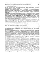
Therefore, it is concluded that the designed neurocontroller provides a good tracking of
desired trajectories.
Fig. 3. Response of the Adaptive Controller with Gradient-Type tuning. Actual and desired
joint angles.
Fig. 4. Response of the controller with gradient-type parameter tuning. Representation of
tracking errors
6. Appendix
Lemma 6: For
(
)
n n
ii
K diag K R
´
= and
(
)
T
n
1 2 n
d d ,d , ,d R=
, if
(
)
u Ks
g
n x=- and
ii i
k d³ then
(
)
T
x M u d 0- £
(Ge et al., 1998).
Lemma 7: Let
(
)
V x,t be a Lyapunov function so that
(
)
V x,t 0> ,
(
)
V x,t 0£
. If
(
)
V x,t
is uniformly continuous (Lewis et al., 2003), then
(
)
V x,t 0 as t ¥
(66)
The following theorem is very important in control of non-linear systems, and is due to
Desoer and Vidyasagar, cf. (Desoer & Vidyasagar, 2008)
Theorem 2: Let the closed-loop transfer function
(
)
(
)
n n
H s s
´
be exponentially stable
and strictly proper, and
(
)
h t the corresponding impulse response (obtained by evaluating
the inverse Laplace transform of
(
)
H s ). If
n
2
u , then
n n
2
y h u
¥
= * Ç ,
n
2
y
,
y
is continuous and
(
)
y
t 0 as t ¥ , where h u* denotes the convolution product of
h and
u
.
On the basis of this theorem, it is possible to state the following lemma, (Ge et al., 1998).
Lemma 8: Let
(
)
(
)
(
)
e t h t r t= * , where
(
)
{
}
1
h H s
-
= and
(
)
H s is an n n´ strictly
proper, exponentially stable transfer function. Then
n n n
2 2
r e
¥
Ç
,
n
2
e
, e is
continuous and
( )
e t 0 as t ¥ . If in addition r 0 as t ¥ , then e 0
. (Ge et
al., 1998).
Theorem 3 (UUB by Lyapunov Analysis): If for system
(
)
(
)
x f x,t
g
t= +
(67)
there exists a function
(
)
V x,t with continuous partial derivatives such that for x in a
compact set
n
S Í
(
)
(
)
(
)
V x,t is positive definite, V x,t 0
V x,t 0 for x R
>
< >
(68)
for some R 0> , such that the ball of radius
R is contained in S , then the system is UUB
and the norm of the state is bounded to within a neighborhood of
R .
The following theorem is a modified version of the uniformly ultimately boundedness
theorem of Corless and Leitmann, cf. (Corless & Leitmann, 1981). For more insights the
reader may refer to theorems 1 and 2 in (Dawson et al., 1990) or the theorem 2.15. p. 65 in
(Qu, 1998).
Theorem 4: If V is a Lyapunov candidate function for any given continuous-time system
with the properties
( ) ( )
(
)
( )
2 2
1 2
λ
x t V x t λ x t£ £ (69)
DesignofAdaptiveControllersbasedonChristoffelSymbolsofFirstKind 233
Therefore, it is concluded that the designed neurocontroller provides a good tracking of
desired trajectories.
Fig. 3. Response of the Adaptive Controller with Gradient-Type tuning. Actual and desired
joint angles.
Fig. 4. Response of the controller with gradient-type parameter tuning. Representation of
tracking errors
6. Appendix
Lemma 6: For
( )
n n
ii
K diag K R
´
= and
(
)
T
n
1 2 n
d d ,d , ,d R=
, if
(
)
u Ks
g
n x=- and
ii i
k d³ then
(
)
T
x M u d 0- £
(Ge et al., 1998).
Lemma 7: Let
(
)
V x,t be a Lyapunov function so that
( )
V x,t 0> ,
(
)
V x,t 0£
. If
( )
V x,t
is uniformly continuous (Lewis et al., 2003), then
( )
V x,t 0 as t ¥
(66)
The following theorem is very important in control of non-linear systems, and is due to
Desoer and Vidyasagar, cf. (Desoer & Vidyasagar, 2008)
Theorem 2: Let the closed-loop transfer function
( )
(
)
n n
H s s
´
be exponentially stable
and strictly proper, and
( )
h t the corresponding impulse response (obtained by evaluating
the inverse Laplace transform of
(
)
H s ). If
n
2
u , then
n n
2
y h u
¥
= * Ç ,
n
2
y
,
y
is continuous and
( )
y
t 0 as t ¥ , where h u* denotes the convolution product of
h and
u
.
On the basis of this theorem, it is possible to state the following lemma, (Ge et al., 1998).
Lemma 8: Let
( ) ( )
(
)
e t h t r t= * , where
(
)
{
}
1
h H s
-
= and
(
)
H s is an n n´ strictly
proper, exponentially stable transfer function. Then
n n n
2 2
r e
¥
Ç
,
n
2
e
, e is
continuous and
( )
e t 0 as t ¥ . If in addition r 0 as t ¥ , then e 0
. (Ge et
al., 1998).
Theorem 3 (UUB by Lyapunov Analysis): If for system
( ) ( )
x f x,t g t= +
(67)
there exists a function
( )
V x,t with continuous partial derivatives such that for x in a
compact set
n
S Í
(
)
(
)
(
)
V x,t is positive definite, V x,t 0
V x,t 0 for x R
>
< >
(68)
for some R 0> , such that the ball of radius
R is contained in S , then the system is UUB
and the norm of the state is bounded to within a neighborhood of
R .
The following theorem is a modified version of the uniformly ultimately boundedness
theorem of Corless and Leitmann, cf. (Corless & Leitmann, 1981). For more insights the
reader may refer to theorems 1 and 2 in (Dawson et al., 1990) or the theorem 2.15. p. 65 in
(Qu, 1998).
Theorem 4: If V is a Lyapunov candidate function for any given continuous-time system
with the properties
( ) ( )
(
)
( )
2 2
1 2
λ
x t V x t λ x t£ £ (69)
AdvancesinRobotManipulators234
(
)
(
)
(
)
2 1
V x t 0, if η x t η< > >
(70)
where
2
2 1
1
λ
η η
λ
> (71)
then
( )
[
)
2
1 0
1
λ
x t η t t T,
λ
< " + ¥ (72)
where
T is a finite positive constant.
The following lemma allows to connect the uniform complete observability (UCO) to the
boundedness of the states, (Lewis et al., 1999).
Lemma 9 (Technical Lemma): Consider the linear time-varying system
(
)
(
)
( )
0,B t ,C t
defined by
(
)
(
)
x B t u
y
C t x
=
=
(73)
with
n
x
,
m
u
,
p
y and the elements of
(
)
B t and
( )
C t piecewise
continuous functions of time. Since the state transition matrix is the identity matrix, the
observability grammian is
( )
( ) ( )
0
t
T
0
t
N t,t C τ C τ dτ=
ò
(74)
Let the system be uniformly completely observable with
( )
B t bounded. Then if
( )
u t and
( )
y
t are bounded, the state
(
)
x t is bounded.
7. References
Corless, M. and Leitmann, G. (1981). Continuous State Feedback Guaranteeing Uniform
Ultimate Boundness for Uncertain Dynamics Systems.
IEEE Transactions on
Automatic Control, Vol.26, No. 5, (October 1981) (1139- 1144), ISSN 0018-9286
Dawson, D. M., Qu, Z., Lewis, F. L., and Dorsey, J. F. (1990). Robust Control for the Tracking
of Robot Motion.
International Journal of Control, Vol.52, No. 3, (1990) (581-595), ISSN
0020-7179
Desoer, C. A., and Vidyasagar, M. (2008).
Feedback Systems: Input-Output Properties, Society
for Industrial and Applied Mathematics, ISBN 978-0898716702
Ge, S. S., Lee, T. H. and Harris, C. J. (1998).
Adaptive Neural Network Control of Robotic
Manipulators,
World Scientific Publishing Company, ISBN 978-9810234522, London
Horn, R. A., and Johnson, C. R. (1999).
Topics in Matrix Analysis, Cambridge University
Press, ISBN 978-0521467131
Lewis, F. L., Jagannathan, S. and Yesildirek, A. (1999).
Neural Network Control of Robot
Manipulators and Nonlinear Systems, Taylor and Francis Ltd., ISBN 978-0748405961
Lewis, F. L., Dawson, D. M. and Abdallah, C. T. (2003). Robot Manipulator Control: Theory and
Practice,
Marcel Dekker Inc., ISBN 978-0824740726.
Mulero-Martínez, J.I. (2007). Bandwidth of Mechanical Systems and Design of Emulators
with RBF.
Neurocomputing, Vol.70, No.7-9, (2007) (1453-1465), ISSN 0925-2312
Mulero-Martínez, J.I. (2007a). An Improved Dynamic Neurocontroller Based on Christoffel
Symbols.
IEEE Transactions on Neural Networks, Vol.18, No.3, (May 2007) (865-879),
ISSN 1045-9227
Mulero-Martínez, J.I. (2007b).
Uniform Bounds of the Coriolis/Centripetal Matrix of Serial
Robot Manipulators.
IEEE Transactions on Robotics, Vol.23, No.5, (October 2007)
(1083-1089), ISSN 1552-3098
Mulero-Martínez, J.I. (2009). A New Factorization of the Coriolis/Centripetal Matrix.
Robotica, Vol.27, No.5, (September 2009) (689-700), ISSN 0263-5747
Qu, Z. (1998).
Robust Control of Nonlinear Uncertain Systems, John Wiley and Sons, ISBN 978-
0471115892
Slotine, J.J. and Li, W. (1991)
Applied Nonlinear Control, Prentice-Hall, ISBN 978-0130408907
Spong, M. W. and Vidyasagar, M. (1989).
Robot Dynamics and Control, John Wiley and Sons
Inc., ISBN 978-0471612438.
Wen, J. T. (1990).
A Unified Perspective on Robot Control: The Energy Lyapunov Function
Approach.
International Journal of Adaptive Control and Signal Processing, Vol.4, No. 6
(November, 1990) (487-500)
DesignofAdaptiveControllersbasedonChristoffelSymbolsofFirstKind 235
(
)
(
)
(
)
2 1
V x t 0, if η x t η< > >
(70)
where
2
2 1
1
λ
η η
λ
> (71)
then
( )
[
)
2
1 0
1
λ
x t η t t T,
λ
< " + ¥ (72)
where
T is a finite positive constant.
The following lemma allows to connect the uniform complete observability (UCO) to the
boundedness of the states, (Lewis et al., 1999).
Lemma 9 (Technical Lemma): Consider the linear time-varying system
(
)
(
)
(
)
0,B t ,C t
defined by
(
)
(
)
x B t u
y
C t x
=
=
(73)
with
n
x
,
m
u
,
p
y and the elements of
(
)
B t and
(
)
C t piecewise
continuous functions of time. Since the state transition matrix is the identity matrix, the
observability grammian is
( )
( ) ( )
0
t
T
0
t
N t,t C τ C τ dτ=
ò
(74)
Let the system be uniformly completely observable with
( )
B t bounded. Then if
( )
u t and
(
)
y
t are bounded, the state
(
)
x t is bounded.
7. References
Corless, M. and Leitmann, G. (1981). Continuous State Feedback Guaranteeing Uniform
Ultimate Boundness for Uncertain Dynamics Systems.
IEEE Transactions on
Automatic Control, Vol.26, No. 5, (October 1981) (1139- 1144), ISSN 0018-9286
Dawson, D. M., Qu, Z., Lewis, F. L., and Dorsey, J. F. (1990). Robust Control for the Tracking
of Robot Motion.
International Journal of Control, Vol.52, No. 3, (1990) (581-595), ISSN
0020-7179
Desoer, C. A., and Vidyasagar, M. (2008).
Feedback Systems: Input-Output Properties, Society
for Industrial and Applied Mathematics, ISBN 978-0898716702
Ge, S. S., Lee, T. H. and Harris, C. J. (1998).
Adaptive Neural Network Control of Robotic
Manipulators,
World Scientific Publishing Company, ISBN 978-9810234522, London
Horn, R. A., and Johnson, C. R. (1999).
Topics in Matrix Analysis, Cambridge University
Press, ISBN 978-0521467131
Lewis, F. L., Jagannathan, S. and Yesildirek, A. (1999).
Neural Network Control of Robot
Manipulators and Nonlinear Systems, Taylor and Francis Ltd., ISBN 978-0748405961
Lewis, F. L., Dawson, D. M. and Abdallah, C. T. (2003). Robot Manipulator Control: Theory and
Practice,
Marcel Dekker Inc., ISBN 978-0824740726.
Mulero-Martínez, J.I. (2007). Bandwidth of Mechanical Systems and Design of Emulators
with RBF.
Neurocomputing, Vol.70, No.7-9, (2007) (1453-1465), ISSN 0925-2312
Mulero-Martínez, J.I. (2007a). An Improved Dynamic Neurocontroller Based on Christoffel
Symbols.
IEEE Transactions on Neural Networks, Vol.18, No.3, (May 2007) (865-879),
ISSN 1045-9227
Mulero-Martínez, J.I. (2007b).
Uniform Bounds of the Coriolis/Centripetal Matrix of Serial
Robot Manipulators.
IEEE Transactions on Robotics, Vol.23, No.5, (October 2007)
(1083-1089), ISSN 1552-3098
Mulero-Martínez, J.I. (2009). A New Factorization of the Coriolis/Centripetal Matrix.
Robotica, Vol.27, No.5, (September 2009) (689-700), ISSN 0263-5747
Qu, Z. (1998).
Robust Control of Nonlinear Uncertain Systems, John Wiley and Sons, ISBN 978-
0471115892
Slotine, J.J. and Li, W. (1991)
Applied Nonlinear Control, Prentice-Hall, ISBN 978-0130408907
Spong, M. W. and Vidyasagar, M. (1989).
Robot Dynamics and Control, John Wiley and Sons
Inc., ISBN 978-0471612438.
Wen, J. T. (1990).
A Unified Perspective on Robot Control: The Energy Lyapunov Function
Approach.
International Journal of Adaptive Control and Signal Processing, Vol.4, No. 6
(November, 1990) (487-500)
AdvancesinRobotManipulators236
DevelopmentofaNew2DOFLightweightWristfortheHumanoidRobotARMAR 237
DevelopmentofaNew2DOFLightweightWristfortheHumanoidRobot
ARMAR
AlbertAlbers,JensOttnadandChristianSander
X
Development of a New 2 DOF Lightweight
Wrist for the Humanoid Robot ARMAR
Albert Albers, Jens Ottnad and Christian Sander
IPEK - Institute of Product Development, University of Karlsruhe (TH)
Germany
1. Introduction
The mechatronic design of a humanoid robot is fundamentally different from that of
industrial robots. Industrial robots generally have to meet requirements such as mechanical
stiffness, accuracy and high velocities. The key goal for this humanoid robot is not accuracy,
but the ability to cooperate with humans. In order to enable a robot to interact with humans,
high standards are set for sensors and control of its movements. The robot’s kinematic
properties and range of movements must be adjusted to humans and their environment
(Schäfer, 2000).
1.1 The Humanoid Robot ARMAR
The collaborative research centre 588 “Humanoid Robots – learning and cooperating multi-
modal robots” was established by the “Deutsche Forschungsgemeinschaft” (DFG) in
Karlsruhe in May 2001. In this project, scientists from different academic fields develop
concepts, methods, and concrete mechatronic components for a humanoid robot called
ARMAR (see figure 1) that can share its working space with humans.
Fig. 1. Upper body of the humanoid robot ARMAR III.
11
AdvancesinRobotManipulators238
The long-term target is the interactive work of robots and humans to jointly accomplish
specified tasks. For instance, a simple task like putting dishes into a dishwasher requires
sophisticated skills in cognition and the manipulation of objects. Communication between
robots and humans should be possible in different ways, including speech, touch, and
gestures, thus allowing humans to interact with the robots easily and intuitively. As this is
the main focus of the collaborative research centre, a humanoid upper body on a holonomic
platform for locomotion has been developed. It is planned to increase the mobility of
ARMAR by replacing the platform with legs within the next years, which will lead to
modifications of the upper body.
1.2 State of the Art and Motivation
The focus of this paper is the design and the development process of a new wrist for the
humanoid robot ARMAR. The wrist serves as the connection between forearm and hand.
An implementation of the new modules is planned for the next generations of the humanoid
robot, ARMAR IV and V. The wrist of the current version, ARMAR III, has two degrees of
freedom (Albers et al., 2006) and its rotational axes intersect in one point. ARMAR III has the
ability to move the wrist to the side (± 60°, adduction/abduction) as well as up and down (±
30°, flexion/extension). This is realized by a universal joint in a compact construction. At the
support structure of the forearm all motors for both degrees of freedom are fixed. The gear
ratio is obtained by a ball screw in conjunction with either a timing belt or a cable. The load
transmission is almost free from backlash. The velocity control and the angular
measurement in the wrist are realized by encoders at the motors and by quasi-absolute
angular sensors directly at the joint. To measure the load on the hand, a 6-axis force and
torque sensor is fitted between the wrist and the hand.
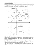
One of the main points of criticism on the current version of the wrist is the offset between
the rotational axes and the flange, as shown in figure 2 (left). Due to the joint design, this
offset distance is necessary in order to provide the desired range of motion. Also other
wrists of humanoid robots show a similar design, see (Shadow), (Kaneko et al., 2004), (Park
et al., 2005), (Kaneko et al., 2008). That offset is even greater due to the placement of the 6-
axis force and torque sensor. The resulting movement, a circular path performed by the
carpus, does not appear as a humanlike motion, as illustrated in figure 2 (right).
offset
offset
Fig. 2. Offset between the rotational axis and the hand flange at the wrist of the humanoid
robot ARMAR III (left) and the resulting movement (right)
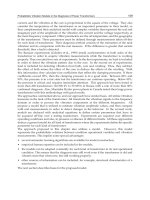
The German Aerospace Centre DLR (Deutsches Zentrum für Luft- und Raumfahrt) has been
working on seven degree of freedom robot arms for several years. The result of this project
is shown in figure 3 (left). Although their work is inspired by a human arm, their goal is not
to design humanoid robots. The wrists of the lightweight arms of the third generation
imitate human wrist movements by a pitch-pitch combination with intersecting axes
(kardanic). An alternative pitch-roll configuration is also utilized, mainly for applications
using tools (Albu-Schäffer et al., 2007). Both versions have an offset comparable to the
current wrist of ARMAR III.
Henry J. Taylor and Philip N.P. Ibbotson designed a so called “Powered Wrist Joint”
(Rosheim, 1989) in order to load and unload space shuttles. The concept of this wrist is
illustrated in figure 3 (right). In a smaller version, the basic idea could be reused in
humanoid robot’s wrist. The second degree of freedom (pitch) of the wrist is guided by a
spherical joint. Such an assembly provides a slim design and relatively wide range of
motion. The actuators for the second degree of freedom (yaw) are located directly at the
joint; therefore, the drive units are quite simple. On the other hand, miniaturization seems to
be very difficult due to the dimensions of common gears and motors.
Fig. 3. The DLR/Kuka lightweight robot arm (Abu-Schäfer et al. 2007) (left) and concept for
a wrist actuator (Rosheim, 1989) (right).
2. New Concept
2.1 Requirements and Design Goals
In this section the system of objectives is defined. It describes all relevant objectives, their
dependence and boundary conditions, which are necessary for the development of the
correct object system, outgoing from the current condition to the future condition. But the
DevelopmentofaNew2DOFLightweightWristfortheHumanoidRobotARMAR 239
The long-term target is the interactive work of robots and humans to jointly accomplish
specified tasks. For instance, a simple task like putting dishes into a dishwasher requires
sophisticated skills in cognition and the manipulation of objects. Communication between
robots and humans should be possible in different ways, including speech, touch, and
gestures, thus allowing humans to interact with the robots easily and intuitively. As this is
the main focus of the collaborative research centre, a humanoid upper body on a holonomic
platform for locomotion has been developed. It is planned to increase the mobility of
ARMAR by replacing the platform with legs within the next years, which will lead to
modifications of the upper body.
1.2 State of the Art and Motivation
The focus of this paper is the design and the development process of a new wrist for the
humanoid robot ARMAR. The wrist serves as the connection between forearm and hand.
An implementation of the new modules is planned for the next generations of the humanoid
robot, ARMAR IV and V. The wrist of the current version, ARMAR III, has two degrees of
freedom (Albers et al., 2006) and its rotational axes intersect in one point. ARMAR III has the
ability to move the wrist to the side (± 60°, adduction/abduction) as well as up and down (±
30°, flexion/extension). This is realized by a universal joint in a compact construction. At the
support structure of the forearm all motors for both degrees of freedom are fixed. The gear
ratio is obtained by a ball screw in conjunction with either a timing belt or a cable. The load
transmission is almost free from backlash. The velocity control and the angular
measurement in the wrist are realized by encoders at the motors and by quasi-absolute
angular sensors directly at the joint. To measure the load on the hand, a 6-axis force and
torque sensor is fitted between the wrist and the hand.
One of the main points of criticism on the current version of the wrist is the offset between
the rotational axes and the flange, as shown in figure 2 (left). Due to the joint design, this
offset distance is necessary in order to provide the desired range of motion. Also other
wrists of humanoid robots show a similar design, see (Shadow), (Kaneko et al., 2004), (Park
et al., 2005), (Kaneko et al., 2008). That offset is even greater due to the placement of the 6-
axis force and torque sensor. The resulting movement, a circular path performed by the
carpus, does not appear as a humanlike motion, as illustrated in figure 2 (right).
offset
offset
Fig. 2. Offset between the rotational axis and the hand flange at the wrist of the humanoid
robot ARMAR III (left) and the resulting movement (right)
The German Aerospace Centre DLR (Deutsches Zentrum für Luft- und Raumfahrt) has been
working on seven degree of freedom robot arms for several years. The result of this project
is shown in figure 3 (left). Although their work is inspired by a human arm, their goal is not
to design humanoid robots. The wrists of the lightweight arms of the third generation
imitate human wrist movements by a pitch-pitch combination with intersecting axes
(kardanic). An alternative pitch-roll configuration is also utilized, mainly for applications
using tools (Albu-Schäffer et al., 2007). Both versions have an offset comparable to the
current wrist of ARMAR III.
Henry J. Taylor and Philip N.P. Ibbotson designed a so called “Powered Wrist Joint”
(Rosheim, 1989) in order to load and unload space shuttles. The concept of this wrist is
illustrated in figure 3 (right). In a smaller version, the basic idea could be reused in
humanoid robot’s wrist. The second degree of freedom (pitch) of the wrist is guided by a
spherical joint. Such an assembly provides a slim design and relatively wide range of
motion. The actuators for the second degree of freedom (yaw) are located directly at the
joint; therefore, the drive units are quite simple. On the other hand, miniaturization seems to
be very difficult due to the dimensions of common gears and motors.
Fig. 3. The DLR/Kuka lightweight robot arm (Abu-Schäfer et al. 2007) (left) and concept for
a wrist actuator (Rosheim, 1989) (right).
2. New Concept
2.1 Requirements and Design Goals
In this section the system of objectives is defined. It describes all relevant objectives, their
dependence and boundary conditions, which are necessary for the development of the
correct object system, outgoing from the current condition to the future condition. But the
AdvancesinRobotManipulators240
solution itself is no part of the system of objectives. It is permanently extended and
concretized over the complete product lifecycle. The correct, consistently and complete
definition of this system is the basis of the successful product development and a core
component of the development activity (Albers et al., 2008a). Since the robot is intended to
get in contact with humans in order to achieve various functions, it is inevitable that the
robot is accepted by the human. The ability to move like a human is as important as a
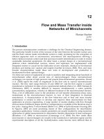
human-like appearance; therefore, specific demands (Asfour, 2003) on kinematics, dynamics
and the design space must to be considered. A human wrist consists of many different
elements and has a relatively wide range of motions. Figure 4 illustrates the different
possible movements of the human wrist along with the corresponding reachable angular
position of the joints (Whired, 2001).
0°
a
b
c
0°
d
Fig. 4. Human wrist and range of motion: a = palmar flexion 70°, b = dorsal flexion 90°, c =
radial abduction 20°, d = ulnar abduction 40° (Whired, 2001).
In order to implement a human-like wrist movement, two orthogonally arranged rotational
degrees of freedom are necessary. Both axes are orthogonal to the forearm’s axis and
intersect in one point. The two degrees of freedom need to be put in a kinematical series.
The requirements and design goals for a humanoid robot’s wrist can be deduced based on
the range of motion of the human wrist. The first degree of freedom should have a ±30°
range of motion and the second about ±90°. The wrist will be attached to the forearm’s
structure on one side and provides the connection to the hand. It should be possible to
disconnect the mechanical joint between the hand and wrist in a simple way in order to
enable a modular design. To measure the load on the hand, a 6-axis force and torque sensor
must be fitted between the wrist and the hand. The electronic cables and pneumatic tubes
supplying power to the hand actuators are the similar to those used in the previous models
of ARMAR (Schulz, 2003; Beck et al., 2003). The design space for the robot’s wrist is based
on human dimensions as far as possible; therefore, one aim is to keep a sphere of
approximately 100 mm in diameter as a boundary. At the same time, the control strategy
aims to operate all degrees of freedom as individually as possible.
In keeping with the standardized drive concept of most modules of the robot, electronic
motors are used as the source for actuation. The drive units need to be dimensioned for a
load of 3 kg. All gears are designed to be free from backlash and not self-locking. But
friction, e.g. in case of a loss of power, leads to a slow and damped sinking of the arm
instead of abrupt movement. That is of great importance for an interactive application of the
robot in a human environment. On the other hand, stick-slip effects in the gears have been
avoided, which is a clear benefit for the control system.
Finally, the mechanical structures should be as light as possible in order to save energy
during dynamic movements. A lower mass of the wrist can contribute significantly to a
reduced energy consumption of the whole arm and has a strong influence on the gears and
motors used for the drive units for the elbow and shoulder degrees of freedom.
2.2 Concepts
A simple reduction of the wrist’s length by only minor modifications is not possible. This is
mainly because the current joint design in combination with the drive unit for the second
degree of freedom does not allow a mounting of the hand in the rotational axis. Formulated
in an abstract way, the development goal is to shift material from the intersection point to a
different location in order to gain free space in the centre position.
Bodies in general have six degrees of freedom in a three dimensional space: three rotational,
and three translational. Due to design complexity, the degrees of freedom must be reduced
for the development of a technical joint. As technical solutions in robotics usually have only
one degree of freedom, it is necessary to combine two basic joints to implement a two degree
of freedom joint (Brudniok 2007). An alternative solution is a spherical joint where one
rotation is blocked, but actuators for such a design have not yet been sufficiently developed.
As result of these basic considerations, two principle solutions were found: a universal joint
and a kind of curved track as depicted in figure 5.
D
E
Fig. 5. Universal joint (left) and the principle curved track solution (right).
To illustrate the decision process within the development both concepts are discussed
shortly. The universal joint concept (figure 5 left) is very similar to the current solution
running on ARMAR III. The first degree of freedom is provided by a rectangular frame (A).
On that frame there is enough space for the bearings (B) of the second degree of freedom.
Finally, the hand can be mounted on the plate (C). In contrast to the current version, the
reduced length was achieved by taking all elements in one plane. The disadvantage is that
the outer diameter has to be enlarged in order to provide the wide range of motion
described in the previous section. One possible implementation of the drive units could be a
direct connection by bowden cables providing a slim and light design of the joint itself. By
applying this idea to the universal joint, the total length (TL) of each cable changes. Figure 6
illustrates the parameters which are of importance for a two dimensional consideration.
DevelopmentofaNew2DOFLightweightWristfortheHumanoidRobotARMAR 241
solution itself is no part of the system of objectives. It is permanently extended and
concretized over the complete product lifecycle. The correct, consistently and complete
definition of this system is the basis of the successful product development and a core
component of the development activity (Albers et al., 2008a). Since the robot is intended to
get in contact with humans in order to achieve various functions, it is inevitable that the
robot is accepted by the human. The ability to move like a human is as important as a
human-like appearance; therefore, specific demands (Asfour, 2003) on kinematics, dynamics
and the design space must to be considered. A human wrist consists of many different
elements and has a relatively wide range of motions. Figure 4 illustrates the different
possible movements of the human wrist along with the corresponding reachable angular
position of the joints (Whired, 2001).
0°
a
b
c
0°
d
Fig. 4. Human wrist and range of motion: a = palmar flexion 70°, b = dorsal flexion 90°, c =
radial abduction 20°, d = ulnar abduction 40° (Whired, 2001).
In order to implement a human-like wrist movement, two orthogonally arranged rotational
degrees of freedom are necessary. Both axes are orthogonal to the forearm’s axis and
intersect in one point. The two degrees of freedom need to be put in a kinematical series.
The requirements and design goals for a humanoid robot’s wrist can be deduced based on
the range of motion of the human wrist. The first degree of freedom should have a ±30°
range of motion and the second about ±90°. The wrist will be attached to the forearm’s
structure on one side and provides the connection to the hand. It should be possible to
disconnect the mechanical joint between the hand and wrist in a simple way in order to
enable a modular design. To measure the load on the hand, a 6-axis force and torque sensor
must be fitted between the wrist and the hand. The electronic cables and pneumatic tubes
supplying power to the hand actuators are the similar to those used in the previous models
of ARMAR (Schulz, 2003; Beck et al., 2003). The design space for the robot’s wrist is based
on human dimensions as far as possible; therefore, one aim is to keep a sphere of
approximately 100 mm in diameter as a boundary. At the same time, the control strategy
aims to operate all degrees of freedom as individually as possible.
In keeping with the standardized drive concept of most modules of the robot, electronic
motors are used as the source for actuation. The drive units need to be dimensioned for a
load of 3 kg. All gears are designed to be free from backlash and not self-locking. But
friction, e.g. in case of a loss of power, leads to a slow and damped sinking of the arm
instead of abrupt movement. That is of great importance for an interactive application of the
robot in a human environment. On the other hand, stick-slip effects in the gears have been
avoided, which is a clear benefit for the control system.
Finally, the mechanical structures should be as light as possible in order to save energy
during dynamic movements. A lower mass of the wrist can contribute significantly to a
reduced energy consumption of the whole arm and has a strong influence on the gears and
motors used for the drive units for the elbow and shoulder degrees of freedom.
2.2 Concepts
A simple reduction of the wrist’s length by only minor modifications is not possible. This is
mainly because the current joint design in combination with the drive unit for the second
degree of freedom does not allow a mounting of the hand in the rotational axis. Formulated
in an abstract way, the development goal is to shift material from the intersection point to a
different location in order to gain free space in the centre position.
Bodies in general have six degrees of freedom in a three dimensional space: three rotational,
and three translational. Due to design complexity, the degrees of freedom must be reduced
for the development of a technical joint. As technical solutions in robotics usually have only
one degree of freedom, it is necessary to combine two basic joints to implement a two degree
of freedom joint (Brudniok 2007). An alternative solution is a spherical joint where one
rotation is blocked, but actuators for such a design have not yet been sufficiently developed.
As result of these basic considerations, two principle solutions were found: a universal joint
and a kind of curved track as depicted in figure 5.
D
E
Fig. 5. Universal joint (left) and the principle curved track solution (right).
To illustrate the decision process within the development both concepts are discussed
shortly. The universal joint concept (figure 5 left) is very similar to the current solution
running on ARMAR III. The first degree of freedom is provided by a rectangular frame (A).
On that frame there is enough space for the bearings (B) of the second degree of freedom.
Finally, the hand can be mounted on the plate (C). In contrast to the current version, the
reduced length was achieved by taking all elements in one plane. The disadvantage is that
the outer diameter has to be enlarged in order to provide the wide range of motion
described in the previous section. One possible implementation of the drive units could be a
direct connection by bowden cables providing a slim and light design of the joint itself. By
applying this idea to the universal joint, the total length (TL) of each cable changes. Figure 6
illustrates the parameters which are of importance for a two dimensional consideration.
AdvancesinRobotManipulators242
l
b
a
q
α
Fig. 6. “Changing” length of the cables in different angular positions of the wrist.
The total lenght can easily be calculated by the following formula, where denotes the
angle between the cables and the middle axis of the forearm:
)cos(
2
l
baTL
(1)
As depends on the angular position of the wrist, TL changes during each movement. That
means that the different degrees of freedom can not be run independently as long as
electronic motors are used as actuators. The Shadow Hand, for example, uses a different
concept concerning the cables and their changing lengths (Shadow).
The second basic concept depicted in figure 5 on the right side consists of a curved track
solution for the first degree of freedom (D). As this first rotation is limited to ±30°, there is
enough space left for the bearings of the second degree of freedom, which may be realized,
e.g., by a simple shaft (E). This configuration allows a relatively wide range of motion and a
high capability for a reduction of the wrist’s length. The challenges for this concept include
finding a technical solution for the curved track, a suitable actuation and a design with a
proper stiffness in the structures.
Overall, both basic concepts fulfill the principle requirement of length reduction. The curved
track method, however, has a clear advantage in terms of size in the radial direction. The
oval outer contour also shows a better similarity to a human wrist; therefore, the curved
track concept was selected for further development.
2.3 Embodiment Design
By an appropriate design of the shaft (see figure 5 right, named E) it is possible to gain still
more space for the 6-axis force and torque sensor. Figure 7 illustrates a cross-section view of
the modified shaft. The depth of the shell corresponds with the radius of the curved track
and enables a mounting of the hand exactly in the point where the rotational axes intersect.
This is achieved by shifting the mechanical connection in the negative direction along the
center axis of the forearm.
6‐axis‐forceand torque sensor
6‐axis‐forceand torque sensor
Fig. 7. Basic idea for the shaft of the second DOF of the wrist integrating the force sensor.
For the technical implementation of the curved track, a curved guide named HCR
manufactured by THK was selected. Used for medical applications, THK produces ceramic
curved guides with a radius of approximately 100 mm. From a technical standpoint it would
have been possible to reduce the radius to meet the requirements for a humanoid robot’s
wrist. For economic reasons, however, this was not a feasible option for the collaborative
research centre. Therefore, a different solution was necessary.
The curved guide was replaced by rollers in combination with a timing belt. This allowed
the integration of two different functions in one element: the timing belt functions as part of
the drive unit while also providing sufficient pre-load to avoid a gap between the rollers
and the track. Figure 8 shows the basic CAD model of each design.
Fig. 8. First technical solution by using a curved guide (left) and the alternative using a roll
timing belt combination (right).
3. Simulation
3.1 Basic Geometric Considerations
Based on the new concept an analytic model can be set up. Therefore all geometrical
parameters based on the nature of the human body have to be adapted to the model. The
undefined variables have to be calculated and estimated using the analytical model to get a
reasonable set of values for the design. Using parameter optimization the best combination
of values for a design proposal can be found in order to achieve reasonable preloads for the
belt.
Two main load cases were used whereas the angle of the initiated force φ can vary. Figure 9
illustrates these two load cases. Here the calculated force F (36 N) is the substitute for all
external loads and self-weight (Albers et al., 2006). M is the appropriate torque resulting
DevelopmentofaNew2DOFLightweightWristfortheHumanoidRobotARMAR 243
l
b
a
q
α
Fig. 6. “Changing” length of the cables in different angular positions of the wrist.
The total lenght can easily be calculated by the following formula, where denotes the
angle between the cables and the middle axis of the forearm:
)cos(
2
l
baTL
(1)
As depends on the angular position of the wrist, TL changes during each movement. That
means that the different degrees of freedom can not be run independently as long as
electronic motors are used as actuators. The Shadow Hand, for example, uses a different
concept concerning the cables and their changing lengths (Shadow).
The second basic concept depicted in figure 5 on the right side consists of a curved track
solution for the first degree of freedom (D). As this first rotation is limited to ±30°, there is
enough space left for the bearings of the second degree of freedom, which may be realized,
e.g., by a simple shaft (E). This configuration allows a relatively wide range of motion and a
high capability for a reduction of the wrist’s length. The challenges for this concept include
finding a technical solution for the curved track, a suitable actuation and a design with a
proper stiffness in the structures.
Overall, both basic concepts fulfill the principle requirement of length reduction. The curved
track method, however, has a clear advantage in terms of size in the radial direction. The
oval outer contour also shows a better similarity to a human wrist; therefore, the curved
track concept was selected for further development.
2.3 Embodiment Design
By an appropriate design of the shaft (see figure 5 right, named E) it is possible to gain still
more space for the 6-axis force and torque sensor. Figure 7 illustrates a cross-section view of
the modified shaft. The depth of the shell corresponds with the radius of the curved track
and enables a mounting of the hand exactly in the point where the rotational axes intersect.
This is achieved by shifting the mechanical connection in the negative direction along the
center axis of the forearm.
6‐axis‐forceand torque sensor
6‐axis‐forceand torque sensor
Fig. 7. Basic idea for the shaft of the second DOF of the wrist integrating the force sensor.
For the technical implementation of the curved track, a curved guide named HCR
manufactured by THK was selected. Used for medical applications, THK produces ceramic
curved guides with a radius of approximately 100 mm. From a technical standpoint it would
have been possible to reduce the radius to meet the requirements for a humanoid robot’s
wrist. For economic reasons, however, this was not a feasible option for the collaborative
research centre. Therefore, a different solution was necessary.
The curved guide was replaced by rollers in combination with a timing belt. This allowed
the integration of two different functions in one element: the timing belt functions as part of
the drive unit while also providing sufficient pre-load to avoid a gap between the rollers
and the track. Figure 8 shows the basic CAD model of each design.
Fig. 8. First technical solution by using a curved guide (left) and the alternative using a roll
timing belt combination (right).
3. Simulation
3.1 Basic Geometric Considerations
Based on the new concept an analytic model can be set up. Therefore all geometrical
parameters based on the nature of the human body have to be adapted to the model. The
undefined variables have to be calculated and estimated using the analytical model to get a
reasonable set of values for the design. Using parameter optimization the best combination
of values for a design proposal can be found in order to achieve reasonable preloads for the
belt.
Two main load cases were used whereas the angle of the initiated force φ can vary. Figure 9
illustrates these two load cases. Here the calculated force F (36 N) is the substitute for all
external loads and self-weight (Albers et al., 2006). M is the appropriate torque resulting
AdvancesinRobotManipulators244
from the arm of lever and is about 3.14 Nm. To avoid a displacement of the cap the preload
F
V
has to be chosen great enough
F
V
3
2
M
V
F
V
3
1
F
φ
M
r
d
e
friction (μ)
ζ
F
φ
M
Fig. 9. Load case I (left) and load case II (right) in two different directions.
Load case I:
The external load F is applied in a variable angle φ towards the vertical line. The maximum
required preload for an offset of the beveled wheels (d) of 37.5 mm is about 1 kN. When d is
increased to 42.5 mm, the required force is less than 0.63 kN. Thus, the required force
decreases by about 37 % when the off-set of the beveled wheels is increased by about 21 %.
By doubling the distance from 35 mm to 70 mm, the required preload force is reduced by
90 %. The calculated critical angle of the load φ is 36°.
Load case II:
Calculations have shown that the influence of the substituted shear force F is negligible for
this load case. Therefore only the over-all torque M is used for the analysis. F
V
is dependent
upon the angle ς and the wheel distance e. The calculated maximum force for the timing belt
is 0.28 kN. The calculated forces are all in a reasonable range compared to the technical
elements that can be used for the construction. Consequently the concept can be realized in a
physical system with standard bearings and materials.
3.2 First Design and Finite Element Analysis
On the basis of the analytic results described in section 3.1, the optimal solution for the free
geometrical parameters can be defined and in a further step be designed in a CAD system.
An impression of the parameter optimized wrist is given in figure 10:
Fig. 10. CAD model based on the results of the analytical considerations.
In a next step the CAD model is simulated numerically using Finite Element Method (FEM)
in order to gain further information of the system’s behavior. Especially the elasticity of the
different structures and the resulting interaction effects are of interest. The preload force and
the orientation of the external force were varied systematically. The primary object is to get
values for the displacement of the cap towards the global coordinate system. ABAQUS
(Dassault Systèmes) is the used solver for the FEM. In order to reduce the computing time,
the CAD model must be simplified while the fundamental behavior of the system should be
modeled as accurately as possible. The following parts are taken into account for the Finite
Element Analysis (FEA): The cap, the beveled wheels, the idler and the timing belt are
modeled as deformable with the ABAQUS- element type ‘C3D8I’ (except beveled wheels,
C3D8R). Analytical rigid elements are used for the connecting wheels and the driving shaft.
All deformable parts are simulated with isotropic material except the timing belt. Due to the
fact that the timing belt is composed of a steel cord with polyurethane backing and teethes,
an anisotropic material parameter is used in the model. The angle φ of the external load
takes the value of 0° and 36° which is identified in the analytic calculation as the most
critical. Figure 11 illustrates the result of the FEA.
Fig. 11. Stress distribution (von-Mises criterion) for load case II.
The stresses, obtained by the FEA show a reasonable distribution. The displacement of the
cap tested with high preload forces is minimal due to the FEA. For a preload of 0.6 kN the
displacement for load case II is about 4.4·10
-3
mm and for load case I 1.39·10
-2
mm.
Compared with a preload of 1 kN the displacement doesn’t highly decrease. For load case II
the displacement takes the value of about 4.07·10
-3
mm and for load case II 1.29·10
-2
mm.
These values for the different preloads show that in the range between F
V
=0.6 and 1.0 kN
only a small increase of positioning accuracy due to less displacement can be reached. But
the high additional costs in the construction of the wrist for preloads higher than 0.6 kN
can’t be justified. For this reason, and for practical implementation, it is not meaningful to
use forces greater than 0.6 kN. For preloads lower than 0.25 kN the position deviation
increases dramatically and the system becomes statically indeterminate. The displacement
of load case I with φ=36° is for every point smallest compared with load case I (φ=0°) and
DevelopmentofaNew2DOFLightweightWristfortheHumanoidRobotARMAR 245
from the arm of lever and is about 3.14 Nm. To avoid a displacement of the cap the preload
F
V
has to be chosen great enough
F
V
3
2
M
V
F
V
3
1
F
φ
M
r
d
e
friction (μ)
ζ
F
φ
M
Fig. 9. Load case I (left) and load case II (right) in two different directions.
Load case I:
The external load F is applied in a variable angle φ towards the vertical line. The maximum
required preload for an offset of the beveled wheels (d) of 37.5 mm is about 1 kN. When d is
increased to 42.5 mm, the required force is less than 0.63 kN. Thus, the required force
decreases by about 37 % when the off-set of the beveled wheels is increased by about 21 %.
By doubling the distance from 35 mm to 70 mm, the required preload force is reduced by
90 %. The calculated critical angle of the load φ is 36°.
Load case II:
Calculations have shown that the influence of the substituted shear force F is negligible for
this load case. Therefore only the over-all torque M is used for the analysis. F
V
is dependent
upon the angle ς and the wheel distance e. The calculated maximum force for the timing belt
is 0.28 kN. The calculated forces are all in a reasonable range compared to the technical
elements that can be used for the construction. Consequently the concept can be realized in a
physical system with standard bearings and materials.
3.2 First Design and Finite Element Analysis
On the basis of the analytic results described in section 3.1, the optimal solution for the free
geometrical parameters can be defined and in a further step be designed in a CAD system.
An impression of the parameter optimized wrist is given in figure 10:
Fig. 10. CAD model based on the results of the analytical considerations.
In a next step the CAD model is simulated numerically using Finite Element Method (FEM)
in order to gain further information of the system’s behavior. Especially the elasticity of the
different structures and the resulting interaction effects are of interest. The preload force and
the orientation of the external force were varied systematically. The primary object is to get
values for the displacement of the cap towards the global coordinate system. ABAQUS
(Dassault Systèmes) is the used solver for the FEM. In order to reduce the computing time,
the CAD model must be simplified while the fundamental behavior of the system should be
modeled as accurately as possible. The following parts are taken into account for the Finite
Element Analysis (FEA): The cap, the beveled wheels, the idler and the timing belt are
modeled as deformable with the ABAQUS- element type ‘C3D8I’ (except beveled wheels,
C3D8R). Analytical rigid elements are used for the connecting wheels and the driving shaft.
All deformable parts are simulated with isotropic material except the timing belt. Due to the
fact that the timing belt is composed of a steel cord with polyurethane backing and teethes,
an anisotropic material parameter is used in the model. The angle φ of the external load
takes the value of 0° and 36° which is identified in the analytic calculation as the most
critical. Figure 11 illustrates the result of the FEA.
Fig. 11. Stress distribution (von-Mises criterion) for load case II.
The stresses, obtained by the FEA show a reasonable distribution. The displacement of the
cap tested with high preload forces is minimal due to the FEA. For a preload of 0.6 kN the
displacement for load case II is about 4.4·10
-3
mm and for load case I 1.39·10
-2
mm.
Compared with a preload of 1 kN the displacement doesn’t highly decrease. For load case II
the displacement takes the value of about 4.07·10
-3
mm and for load case II 1.29·10
-2
mm.
These values for the different preloads show that in the range between F
V
=0.6 and 1.0 kN
only a small increase of positioning accuracy due to less displacement can be reached. But
the high additional costs in the construction of the wrist for preloads higher than 0.6 kN
can’t be justified. For this reason, and for practical implementation, it is not meaningful to
use forces greater than 0.6 kN. For preloads lower than 0.25 kN the position deviation
increases dramatically and the system becomes statically indeterminate. The displacement
of load case I with φ=36° is for every point smallest compared with load case I (φ=0°) and
AdvancesinRobotManipulators246
load case II. Therefore, it appears that a preload between 0.25 kN and 0.6 kN would be most
suitable.
4. Functional Prototype
Based on the positive results obtained by the different simulations, a functional prototype
was developed. That was necessary mainly because different functions were integrated in
the toothed belt, which is usually used in a different manner and not all material parameters
were available so that estimated values were used.
As the purpose of the prototype is to prove basic functionality of the design, a few
simplifications are made. For the beveled wheels complete rolls are used and the cap is
designed in a simple way for instance. Further-more, the construction allows the possibility
to implement an s-beam force sensor (Lorenz K-25). Figure 12 shows two pictures of the
assembled functional prototype with a one kilogram weight attached at the hand’s position.
Fig. 12. Functional prototype.
Multiple static and dynamic tests show that this configuration is very accurate and has a
high stiffness for small preloads of about 300 N. Hereby the wrist is hand-held at the
forearm tube and statically loaded by huge forces between 20-80 N or moved dynamically in
all different directions. Even for very fast “hand actuated” motions, which were
approximately five times of the maximum velocity of the robot’s arm, the assembly
remained free from backlash.
5. Optimization and Lightweight Design
As a lightweight design is one of the main goals for the development of the new wrist,
different numerical optimization methods were used.
5.1 Topology Optimization
Topology optimization is used for the determination of the basic layout of a new design. It
involves the determination of features such as the number, location and shape of holes, and
the connectivity of the domain. A new design is determined based upon the design space
available, the loads, possible bearings, and materials of which the component is to be
composed. Today topology optimization is very well theoretically studied (Bendsoe &
Sigmund, 2003) and also a common tool in the industrial design process (Pedersen &
Allinger, 2005). The designs, obtained using topology optimization are considered as design
proposals. These topology optimized designs can often be rather different compared to
designs obtained with a trial and error design process or designs obtained from
improvements of existing layouts. The standard formulation in topology optimization is
often to minimize the compliance corresponding to maximize the stiffness using a mass
constraint for a given amount of material. That means that for a predefined amount of mass
the structure with the highest stiffness is determined. Compliance optimization is based
upon static structural analyses, modal analyses or even non-linear problems, such as models
including contacts. A topology optimization scheme is basically an iterative process that
integrates a finite element solver and an optimization module. Based on a design response
supplied by the FE solver (e.g. strain energy), the topology optimization module modifies
the FE model.
5.2 Material Optimization
Besides the topology optimization, it is necessary in addition to consider optimization
strategies such as material optimization. Extreme lightweight design is possible only by
combining both optimization strategies such as the topology optimization in combination
with an optimal fiber layout. For calculation of laminates by use of the Finite Element
Method (FEM), approaches are used that combine the properties of single plies to one
virtual material by use of the ‘Classical Lamination Theory’ (CLT) (Johns, 1999). These
established theories are valid for the elastic range.
Several approaches for the determination of optimal fiber orientation have been presented in
the past. (Luo & Gea, 1998) use an energy based method. (Setoodeh, 2005) describes an
optimality criteria approach, while (Jansson, 2007) works with a generic algorithm. Inspired
by nature (Kriechbaum 1994), (Hyer & Charette, 1987) place fibres in direction of first
principal stress. In that context (Lederman, 2003) presents a method placing the fibers in the
direction of the first main stress in the finite element. (Pedersen, 1991) showed, that a fiber
orientation according to the first main strains leads to maximization of stiffness. Most of
those approaches only work for one layer, and are reduced on two dimensional problems.
The method used in that work was developed by (Albers et al., 2008b), focusing two main
goals: Fast convergence, because the approach is intended to be used together with FEM,
and, in a second step, combination with topology optimization. Application should be
possible for 3D-geometries, and determination of a two layered laminate structure
(orientation and thicknesses) had to be possible to take multi-axial load cases into account.
The approach is based on a theory described by (Ledermann, 2003). Optimal fiber
orientation is found, if it is equal to the orientation of the first main stress. To be able to take
multi-axial load cases into account, the method creates two plies per finite element, with the
second ply oriented in the direction of the second main stress. The relation of thickness of
the two plies is proportional to the relation of the two main stresses. The orientation of the
composite in space is defined by the surface created by the two directions of the main
stresses. The third main stress is not taken into account, because 3-dimensional canvases are
normally not used in real world applications.
The method is implemented in an iterative procedure, starting with a finite element model
with isotropic material. Thenceforward, the isotropic material model is replaced by an
anisotropic one with the parameters of a combined two-layer composite. Stress and ply
directions are updated in every iteration. In detail, the following steps are undertaken in
each iteration: From the preceding finite element analysis, main stress directions and -
amounts are determined for each finite element. The procedure starts with the
DevelopmentofaNew2DOFLightweightWristfortheHumanoidRobotARMAR 247
load case II. Therefore, it appears that a preload between 0.25 kN and 0.6 kN would be most
suitable.
4. Functional Prototype
Based on the positive results obtained by the different simulations, a functional prototype
was developed. That was necessary mainly because different functions were integrated in
the toothed belt, which is usually used in a different manner and not all material parameters
were available so that estimated values were used.
As the purpose of the prototype is to prove basic functionality of the design, a few
simplifications are made. For the beveled wheels complete rolls are used and the cap is
designed in a simple way for instance. Further-more, the construction allows the possibility
to implement an s-beam force sensor (Lorenz K-25). Figure 12 shows two pictures of the
assembled functional prototype with a one kilogram weight attached at the hand’s position.
Fig. 12. Functional prototype.
Multiple static and dynamic tests show that this configuration is very accurate and has a
high stiffness for small preloads of about 300 N. Hereby the wrist is hand-held at the
forearm tube and statically loaded by huge forces between 20-80 N or moved dynamically in
all different directions. Even for very fast “hand actuated” motions, which were
approximately five times of the maximum velocity of the robot’s arm, the assembly
remained free from backlash.
5. Optimization and Lightweight Design
As a lightweight design is one of the main goals for the development of the new wrist,
different numerical optimization methods were used.
5.1 Topology Optimization
Topology optimization is used for the determination of the basic layout of a new design. It
involves the determination of features such as the number, location and shape of holes, and
the connectivity of the domain. A new design is determined based upon the design space
available, the loads, possible bearings, and materials of which the component is to be
composed. Today topology optimization is very well theoretically studied (Bendsoe &
Sigmund, 2003) and also a common tool in the industrial design process (Pedersen &
Allinger, 2005). The designs, obtained using topology optimization are considered as design
proposals. These topology optimized designs can often be rather different compared to
designs obtained with a trial and error design process or designs obtained from
improvements of existing layouts. The standard formulation in topology optimization is
often to minimize the compliance corresponding to maximize the stiffness using a mass
constraint for a given amount of material. That means that for a predefined amount of mass
the structure with the highest stiffness is determined. Compliance optimization is based
upon static structural analyses, modal analyses or even non-linear problems, such as models
including contacts. A topology optimization scheme is basically an iterative process that
integrates a finite element solver and an optimization module. Based on a design response
supplied by the FE solver (e.g. strain energy), the topology optimization module modifies
the FE model.
5.2 Material Optimization
Besides the topology optimization, it is necessary in addition to consider optimization
strategies such as material optimization. Extreme lightweight design is possible only by
combining both optimization strategies such as the topology optimization in combination
with an optimal fiber layout. For calculation of laminates by use of the Finite Element
Method (FEM), approaches are used that combine the properties of single plies to one
virtual material by use of the ‘Classical Lamination Theory’ (CLT) (Johns, 1999). These
established theories are valid for the elastic range.
Several approaches for the determination of optimal fiber orientation have been presented in
the past. (Luo & Gea, 1998) use an energy based method. (Setoodeh, 2005) describes an
optimality criteria approach, while (Jansson, 2007) works with a generic algorithm. Inspired
by nature (Kriechbaum 1994), (Hyer & Charette, 1987) place fibres in direction of first
principal stress. In that context (Lederman, 2003) presents a method placing the fibers in the
direction of the first main stress in the finite element. (Pedersen, 1991) showed, that a fiber
orientation according to the first main strains leads to maximization of stiffness. Most of
those approaches only work for one layer, and are reduced on two dimensional problems.
The method used in that work was developed by (Albers et al., 2008b), focusing two main
goals: Fast convergence, because the approach is intended to be used together with FEM,
and, in a second step, combination with topology optimization. Application should be
possible for 3D-geometries, and determination of a two layered laminate structure
(orientation and thicknesses) had to be possible to take multi-axial load cases into account.
The approach is based on a theory described by (Ledermann, 2003). Optimal fiber
orientation is found, if it is equal to the orientation of the first main stress. To be able to take
multi-axial load cases into account, the method creates two plies per finite element, with the
second ply oriented in the direction of the second main stress. The relation of thickness of
the two plies is proportional to the relation of the two main stresses. The orientation of the
composite in space is defined by the surface created by the two directions of the main
stresses. The third main stress is not taken into account, because 3-dimensional canvases are
normally not used in real world applications.
The method is implemented in an iterative procedure, starting with a finite element model
with isotropic material. Thenceforward, the isotropic material model is replaced by an
anisotropic one with the parameters of a combined two-layer composite. Stress and ply
directions are updated in every iteration. In detail, the following steps are undertaken in
each iteration: From the preceding finite element analysis, main stress directions and -
amounts are determined for each finite element. The procedure starts with the
AdvancesinRobotManipulators248
transformation of the direction vectors of main stresses from the element coordinate systems
to the vector of the global system by use of the direction cosines. The cross product of the
direction vectors of the two first main stresses is used to define the perpendicular to the later
surface of lamina of the element. In the special case of the cross product being the zero-
vector, e.g. the uniaxial stress condition, a filter is used to determine the perpendicular out
of the neighboring elements. By use of the given engineering constants E
║
, E
┴
,
┴║
,
┴┴
and
G
┴║
of the chosen fiber-matrix-combination, the orthotropic stiffness matrix [C] of the UD-
layers can be reduced to a transversal isotropic one as follows:
66
55
44
333231
332221
131211
00
00
00
000
000
000
000
000
000
C
C
C
CCC
CCC
CCC
C
(2)
with
32
3223
11
1
EE
C
,
31
3113
22
1
EE
C
,
121
2112
33
1
EE
C
31
133212
12
EE
C
,
21
231213
13
EE
C
,
21
132123
23
EE
C
2344
CC
,
1355
CC
,
1266
CC
(3)
and
321
133221133132232112
21
EEE
(4)
Now, the engineering constants mentioned above are introduced:
EEE
32
GGG
2131
2131
12
G
G
(5)
The angle between the two layers is the angle between the two first main stresses. It can be
obtained by use of the direction cosines. The volume share of the two layers is calculated as:
21
1
1
,
12
1
(6)
By use of the ‘Classical Lamination Theory’ (CLT), the combined stiffness matrix [C
com
] of
the two-layer-lamina can now be calculated. First, the stiffness matrix of the smaller layer is
transformed into the lamina coordinate system, defined by the direction of the first main
stress. This is done by rotating the stiffness matrix of the layer [C]’ about :
T
TCTC
'1
(7)
With [T] the following transformation matrix:
22
22
22
sincoscossincossin
cossin2cossin
cossin2sincos
T
(8)
The combination of the two layers is done by use of the rules defined by the CLT. The
iteration is finished by formatting and writing the new anisotropic stiffness matrices in the
input deck for the FEA. Depending on the FE code used, the materials has to be filtered and
clustered before a FEA can be performed, as some FE algorithms are limited in the number
of materials allowed. Reduced convergence speed and accuracy of the approach may result.
5.3 Model Setup
For the topology and material optimization the complete system is disassembled and only
the cap is used for the optimization. This simplification is necessary to avoid enormous
computing time caused by a very fine mesh for the cap and a huge number of load cases.
Cutting these parts free from the total system, calls for a realistic replacement of the
interaction between the components. Hereby the interaction between the beveled wheels
and cap is replaced by a connection at the corresponding nodes which allows a degree of
freedom in the 3-axis direction. This simplification is possible because the appearing forces
can only be compressive force or the cap lifts off the wheel surface. The timing belt is
replaced by a load which is tangential to the cap and transferred to the structure by 5 points
on each side of the cap. The preload used in place of the timing belt is 450 N. On one side of
the cap an additional force is applied to the timing belt which is the result of an inertial relief
and named F
inertrel
. The external load (F) is defined to 30 N and applied to the cap by a
torsion arm, which is modeled as rigid element (RBE in MSC.Nastran), in a distance of
100 mm in negative 3-coordinate-axis. The force vector can be reduced to three different
directions because of the symmetry conditions can be defined for the optimization process.
DevelopmentofaNew2DOFLightweightWristfortheHumanoidRobotARMAR 249
transformation of the direction vectors of main stresses from the element coordinate systems
to the vector of the global system by use of the direction cosines. The cross product of the
direction vectors of the two first main stresses is used to define the perpendicular to the later
surface of lamina of the element. In the special case of the cross product being the zero-
vector, e.g. the uniaxial stress condition, a filter is used to determine the perpendicular out
of the neighboring elements. By use of the given engineering constants E
║
, E
┴
,
┴║
,
┴┴
and
G
┴║
of the chosen fiber-matrix-combination, the orthotropic stiffness matrix [C] of the UD-
layers can be reduced to a transversal isotropic one as follows:
66
55
44
333231
332221
131211
00
00
00
000
000
000
000
000
000
C
C
C
CCC
CCC
CCC
C
(2)
with
32
3223
11
1
EE
C
,
31
3113
22
1
EE
C
,
121
2112
33
1
EE
C
31
133212
12
EE
C
,
21
231213
13
EE
C
,
21
132123
23
EE
C
2344
CC
,
1355
CC
,
1266
CC
(3)
and
321
133221133132232112
21
EEE
(4)
Now, the engineering constants mentioned above are introduced:
EEE
32
GGG
2131
2131
12
G
G
(5)
The angle between the two layers is the angle between the two first main stresses. It can be
obtained by use of the direction cosines. The volume share of the two layers is calculated as:
21
1
1
,
12
1
(6)
By use of the ‘Classical Lamination Theory’ (CLT), the combined stiffness matrix [C
com
] of
the two-layer-lamina can now be calculated. First, the stiffness matrix of the smaller layer is
transformed into the lamina coordinate system, defined by the direction of the first main
stress. This is done by rotating the stiffness matrix of the layer [C]’ about :
T
TCTC
'1
(7)
With [T] the following transformation matrix:
22
22
22
sincoscossincossin
cossin2cossin
cossin2sincos
T
(8)
The combination of the two layers is done by use of the rules defined by the CLT. The
iteration is finished by formatting and writing the new anisotropic stiffness matrices in the
input deck for the FEA. Depending on the FE code used, the materials has to be filtered and
clustered before a FEA can be performed, as some FE algorithms are limited in the number
of materials allowed. Reduced convergence speed and accuracy of the approach may result.
5.3 Model Setup
For the topology and material optimization the complete system is disassembled and only
the cap is used for the optimization. This simplification is necessary to avoid enormous
computing time caused by a very fine mesh for the cap and a huge number of load cases.
Cutting these parts free from the total system, calls for a realistic replacement of the
interaction between the components. Hereby the interaction between the beveled wheels
and cap is replaced by a connection at the corresponding nodes which allows a degree of
freedom in the 3-axis direction. This simplification is possible because the appearing forces
can only be compressive force or the cap lifts off the wheel surface. The timing belt is
replaced by a load which is tangential to the cap and transferred to the structure by 5 points
on each side of the cap. The preload used in place of the timing belt is 450 N. On one side of
the cap an additional force is applied to the timing belt which is the result of an inertial relief
and named F
inertrel
. The external load (F) is defined to 30 N and applied to the cap by a
torsion arm, which is modeled as rigid element (RBE in MSC.Nastran), in a distance of
100 mm in negative 3-coordinate-axis. The force vector can be reduced to three different
directions because of the symmetry conditions can be defined for the optimization process.
AdvancesinRobotManipulators250
The additional torque (M) represents 5 Nm and rotates about the global 3-coodrinate-axis. In
figure 13 eight different load cases are illustrated.
F
V
+F
inertrel
F
V
F
F
V
+F
inertrel
F
V
F
45
F
V
+F
inertrel
F
V
F
F
V
+F
inertrel
F
V
F
F
V
+F
inertrel
F
V
M
F
45
F
F
V
F
45
1. 2. 3.
4.
5.
6.
7. 8.
1.1
1.2
1.3
2.1
2.2
2.3
1.1
1.2
1.3
4.1
4.2
4.3
5.1
5.2
5.3
6.1
6.2
6.3
Fig. 13. Load cases for the topology optimization.
The first six load case combinations are set for three different rotational positions of the
second DOF. The initial state is the neutral position and two other positions are realized by
changing the direction and position of all forces on the cap as they would appear at a
±30° rotation. From this it follows that 18+2=20 different configurations of the cap are set for
the topology optimization.
5.4 Results
The result of the topology optimization as a basic design proposal is shown in figure 14. The
complex topography in the center is a result of the stress caused by the torsional moment
applied to the structure mainly by load case 4 (4.1, 4.2, 4.3). The direct connection to the
bearing by the beveled wheels is visible clearly. The function of the center link is mainly to
absorb the reaction forces applied to the cap by the high preload and the beveled wheels.
The side links are important to reinforce the cap structure between the two points of force
transmission of the timing belt. The shape of an arrowhead as a result of the two side links is
highlighted on the right side in figure 14.
center
center link
side link
side link
Fig. 14. Smoothed design proposal as a results by the optimization for a lightweight
laminate.
In figure 15 the principle stress for an anisotropic topology optimization is illustrated. The
highlighted regions are areas with preferred orientated principle stress, which is important
while using fiber reinforced materials. Furthermore the stress is uniaxial in these regions. A
zoomed view (round clippings) clarifies the stress orientation. In these regions the fibers in
the laminate can be orientated in the direction of the principle stress which on the one hand
reduces the amount of used material and by that the weight of the cap and on the other
hand it improves the stiffness and accuracy. Regions which are not highlighted have
changing stress orientations and different stress states. In these areas laminates have to be
stacked with different orientations to absorb the multiaxial stress.
Fig. 15. Principle stress highlighted for a laminate.
DevelopmentofaNew2DOFLightweightWristfortheHumanoidRobotARMAR 251
The additional torque (M) represents 5 Nm and rotates about the global 3-coodrinate-axis. In
figure 13 eight different load cases are illustrated.
F
V
+F
inertrel
F
V
F
F
V
+F
inertrel
F
V
F
45
F
V
+F
inertrel
F
V
F
F
V
+F
inertrel
F
V
F
F
V
+F
inertrel
F
V
M
F
45
F
F
V
F
45
1. 2. 3.
4.
5.
6.
7. 8.
1.1
1.2
1.3
2.1
2.2
2.3
1.1
1.2
1.3
4.1
4.2
4.3
5.1
5.2
5.3
6.1
6.2
6.3
Fig. 13. Load cases for the topology optimization.
The first six load case combinations are set for three different rotational positions of the
second DOF. The initial state is the neutral position and two other positions are realized by
changing the direction and position of all forces on the cap as they would appear at a
±30° rotation. From this it follows that 18+2=20 different configurations of the cap are set for
the topology optimization.
5.4 Results
The result of the topology optimization as a basic design proposal is shown in figure 14. The
complex topography in the center is a result of the stress caused by the torsional moment
applied to the structure mainly by load case 4 (4.1, 4.2, 4.3). The direct connection to the
bearing by the beveled wheels is visible clearly. The function of the center link is mainly to
absorb the reaction forces applied to the cap by the high preload and the beveled wheels.
The side links are important to reinforce the cap structure between the two points of force
transmission of the timing belt. The shape of an arrowhead as a result of the two side links is
highlighted on the right side in figure 14.
center
center link
side link
side link
Fig. 14. Smoothed design proposal as a results by the optimization for a lightweight
laminate.
In figure 15 the principle stress for an anisotropic topology optimization is illustrated. The
highlighted regions are areas with preferred orientated principle stress, which is important
while using fiber reinforced materials. Furthermore the stress is uniaxial in these regions. A
zoomed view (round clippings) clarifies the stress orientation. In these regions the fibers in
the laminate can be orientated in the direction of the principle stress which on the one hand
reduces the amount of used material and by that the weight of the cap and on the other
hand it improves the stiffness and accuracy. Regions which are not highlighted have
changing stress orientations and different stress states. In these areas laminates have to be
stacked with different orientations to absorb the multiaxial stress.
Fig. 15. Principle stress highlighted for a laminate.
AdvancesinRobotManipulators252
Based on the optimization results a 3D-CAD model can be implemented as a first design
proposal (see figure 16). In order to realize a lightweight design, the part is built up as an
hollow shell. The advantage is that the material is located at the outer area which increases
the bending stiffness. To reduce the comprehensive stress at the friction contact zone where
the beveled wheels are crawling, a metal band is laminated into the fiber composite. This
metal band also increases the stiffness. Furthermore compression proof foam can be
integrated into the shell in areas with high pressure mainly introduced to the structure by
high preloads. The complex suggestion for the center by the topology optimization is
reduced to a thickened center link. To big holes in the structure reduce the weight. In
figure 16 on the right side the arrowhead shape, which was suggested by the optimization,
is visible. This shape allows a good distribution of forces within the structure.
friction contact zone
for the bevel wheels
holes
arrowhead shape
Fig. 16. 3D-CAD model of a design proposal.
Due to the two holes in the structure a new concept for the timing belt is required. Therefore
two narrow belts instead of one are used to apply the preload to the cap. In figure 17 a 3D-
CAD model with a suggestion for the two timing belts is illustrated. This arrangement
increases the support effect and results in a better positioning accuracy.
Fig. 17. 3D-CAD model of a design proposal for the timing belt.
6. Conclusion
In this paper the development of a new concept for humanoid robot’s lightweight wrist is
presented. Especially the different steps of the development process are described. Based on
the basic ideas, different analyses and simulations are conducted. A functional prototype is
presented which is a kind of proof of the concept. Due to the design proposal obtained by
the topology optimization for a fiber composite, a lightweight design is implemented in the
CAD model.
The next step will be the integration of the drive units for the second degree of freedom.
Here different solutions are possible, e.g. like bowden cables or a direct actuation in
combination with harmonic drive gears. In order to achieve a further reduction of mass,
composite materials may be used for some further of the structural components. The new
wrist will be developed in the next months and is to be manufactured and assembled during
the next year.
7. References
Albers A.; Brudniok S.; Ottnad J.; Sauter Ch.; Sedchaicharn K. (2006) Upper Body of a new
Humanoid Robot – the Design of Armar III, Humanoids 06 - 2006 IEEE-RAS
International Conference on Humanoid Robots, December 4 to 6, 2006 in Genova, Italy.
Albers, A.; Deigendesch, T.; Meboldt, M. (2008a). Handling Complexity – A Methodological
Approach Comprising Process and Knowledge Management, Proceedings of the
TMCE 2008, 2008 TMCE International Symposium on Tools and Methods of Competitive
Engineering, April 21-25, 2008, Izmir, Turkey.
Albers, A.; Ottnad, J.; Weiler, W. (2008b). Integrated Topology and Fibre Optimization for 3-
Dimensional Composites, Proceedings of IMECE 2008, 2008 ASME International
Mechanical Engineering Congress and Exposition, November 2-6, 2008, Boston,
Massachusetts, USA.
Albu-Schäffer, A.; Haddadin, S.; Ott, Ch.; Stemmer, A.; Wimböck, T.; Hirzinger, G. (2007).
The DLR lightweight robot: design and control concepts for robots in human
environments, Industrial Robot: An International Journal, Vol. 34 No. 5, 2007.
Asfour, T. (2003). Sensomotorische Bewegungskoordination zur Handlungsausführung eines
humanoiden Roboters, Dissertation Fakultät für Informatik, Universität Karlsruhe,
2003.
Beck, S.; Lehmann, A.; Lotz, Th.; Martin, J.; Keppler, R.; Mikut, R. (2003). Model-based
adaptive control of a fluidic actuated robotic hand, Proc., GMA-Congress 2003, VDI-
Berichte 1756, S. 65-72; 2003.
Bendsoe, M. & Sigmund, O. (2003). Topology Optimization – Theory, Methods, Application,
Springer Verlag 2003.
Brudniok, S. (2007). Dissertation - Methodische Entwicklung hochintegrierter
mechatronischer Systeme am Beispiel eines humanoiden Roboters,
Forschungsberichte des Instituts für Produktentwicklung, Band 26, Karlsruhe 2007,
ISSN 1615-8113.
Hyer, M. W. & Charette, R. F. (1987). Innovative design of composite structures: use of curvilinear
fiber format to improve structural efficiency, Technical Report 87–5, University of
Maryland, College Park, MD, USA, 1987.
DevelopmentofaNew2DOFLightweightWristfortheHumanoidRobotARMAR 253
Based on the optimization results a 3D-CAD model can be implemented as a first design
proposal (see figure 16). In order to realize a lightweight design, the part is built up as an
hollow shell. The advantage is that the material is located at the outer area which increases
the bending stiffness. To reduce the comprehensive stress at the friction contact zone where
the beveled wheels are crawling, a metal band is laminated into the fiber composite. This
metal band also increases the stiffness. Furthermore compression proof foam can be
integrated into the shell in areas with high pressure mainly introduced to the structure by
high preloads. The complex suggestion for the center by the topology optimization is
reduced to a thickened center link. To big holes in the structure reduce the weight. In
figure 16 on the right side the arrowhead shape, which was suggested by the optimization,
is visible. This shape allows a good distribution of forces within the structure.
friction contact zone
for the bevel wheels
holes
arrowhead shape
Fig. 16. 3D-CAD model of a design proposal.
Due to the two holes in the structure a new concept for the timing belt is required. Therefore
two narrow belts instead of one are used to apply the preload to the cap. In figure 17 a 3D-
CAD model with a suggestion for the two timing belts is illustrated. This arrangement
increases the support effect and results in a better positioning accuracy.
Fig. 17. 3D-CAD model of a design proposal for the timing belt.
6. Conclusion
In this paper the development of a new concept for humanoid robot’s lightweight wrist is
presented. Especially the different steps of the development process are described. Based on
the basic ideas, different analyses and simulations are conducted. A functional prototype is
presented which is a kind of proof of the concept. Due to the design proposal obtained by
the topology optimization for a fiber composite, a lightweight design is implemented in the
CAD model.
The next step will be the integration of the drive units for the second degree of freedom.
Here different solutions are possible, e.g. like bowden cables or a direct actuation in
combination with harmonic drive gears. In order to achieve a further reduction of mass,
composite materials may be used for some further of the structural components. The new
wrist will be developed in the next months and is to be manufactured and assembled during
the next year.
7. References
Albers A.; Brudniok S.; Ottnad J.; Sauter Ch.; Sedchaicharn K. (2006) Upper Body of a new
Humanoid Robot – the Design of Armar III, Humanoids 06 - 2006 IEEE-RAS
International Conference on Humanoid Robots, December 4 to 6, 2006 in Genova, Italy.
Albers, A.; Deigendesch, T.; Meboldt, M. (2008a). Handling Complexity – A Methodological
Approach Comprising Process and Knowledge Management, Proceedings of the
TMCE 2008, 2008 TMCE International Symposium on Tools and Methods of Competitive
Engineering, April 21-25, 2008, Izmir, Turkey.
Albers, A.; Ottnad, J.; Weiler, W. (2008b). Integrated Topology and Fibre Optimization for 3-
Dimensional Composites, Proceedings of IMECE 2008, 2008 ASME International
Mechanical Engineering Congress and Exposition, November 2-6, 2008, Boston,
Massachusetts, USA.
Albu-Schäffer, A.; Haddadin, S.; Ott, Ch.; Stemmer, A.; Wimböck, T.; Hirzinger, G. (2007).
The DLR lightweight robot: design and control concepts for robots in human
environments, Industrial Robot: An International Journal, Vol. 34 No. 5, 2007.
Asfour, T. (2003). Sensomotorische Bewegungskoordination zur Handlungsausführung eines
humanoiden Roboters, Dissertation Fakultät für Informatik, Universität Karlsruhe,
2003.
Beck, S.; Lehmann, A.; Lotz, Th.; Martin, J.; Keppler, R.; Mikut, R. (2003). Model-based
adaptive control of a fluidic actuated robotic hand, Proc., GMA-Congress 2003, VDI-
Berichte 1756, S. 65-72; 2003.
Bendsoe, M. & Sigmund, O. (2003). Topology Optimization – Theory, Methods, Application,
Springer Verlag 2003.
Brudniok, S. (2007). Dissertation - Methodische Entwicklung hochintegrierter
mechatronischer Systeme am Beispiel eines humanoiden Roboters,
Forschungsberichte des Instituts für Produktentwicklung, Band 26, Karlsruhe 2007,
ISSN 1615-8113.
Hyer, M. W. & Charette, R. F. (1987). Innovative design of composite structures: use of curvilinear
fiber format to improve structural efficiency, Technical Report 87–5, University of
Maryland, College Park, MD, USA, 1987.
AdvancesinRobotManipulators254
Jansson, N. (2007). Optimization of hybrid thermoplastic composite structures using
surrogate models and genetic algorithms. Composite Structures, Vol. 80 (2007) No.
1, pp. 21-31.
Jones, R. (1999). Mechanics of composite materials - 2. ed, Philadelphia: Taylor & Francis, 1999;
ISBN 1-56032-712-X.
Kaneko, K.; Kanehiro, F.; Kajita S.; Hirukawa, H.;Kawasaki, T.; Hirata, M.; Akachi, K.;
Isozumi, T. (2004). Humanoid Robot HRP-2, Proc. IEEE Int. Conference on Robotics
and Automation, pp. 1083-1090, 2004.
Kaneko, K.; Harada, K.; Kanehiro, F.; Miyamori, G.; Akachi, K. (2008). Humanoid Robot
HRP-3, 2008 IEEE/RSJ International Conference on Intelligent Robots and Systems,
Acropolis Convention Center Nice, France, Sept, 22-26, 2008.
Kriechbaum, R. (1994). Ein Verfahren zur Optimierung der Faserverläufe in Verbundwerkstoffen
durch Minimierung der Schubspannung nach Vorbildern der Natur, FZKA 5406,
Forschungszentrum Karlsruhe, Eggenstein-Leopoldshafen, Germany, 1994.
Ledermann, M. (2003) Dissertation: Beiträge zur Optimierung von Faserverbunden nach dem
Vorbild der Natur, Institut für Materialforschung, Forschungszentrum Karlsruhe;
Wissenschaftliche Berichte FZKA 6779, ISSN 0947-8620. 2003.
Luo J.H., Gea H.C. (1998) Optimal orientation of orthotropic materials using an energy
based method, Structural Optimization, Vol. 15 (1998), No. 3/4, pp. 230-236.
Park, I. W.; Kim, J. Y.; Lee, J.; Oh, J. H. (2005). Mechanical Design of Humanoid Robot
Platform KHR-3 (KAIST Humanoid Robot – 3: HUBO), Proc. IEEE-RAS Int.
Conference on Humanoid Robots, pp. 321-326, 2005.
Pedersen, P. (1991). Optimal orientation of anisotropic materials, optimal distribution of
anisotropic materials, optimal shape design with anisotropic materials, optimal
design for a class of non-linear elasticity, Optimization of large structural systems;
Proceedings of the NATO/DFG Advanced Study Institute (1991), Berchtesgaden,
Germany.
Pedersen, C.B.W. & Allinger, P. (2005) Recent Developments in the Commercial
Implementation of Topology Optimization, TopoptSYMP2005 - IUTAM-Symposium,
Copenhagen, Denmark, pp. 123-132, 2005.
Rosheim, M. (1989). Robot wrist actuators, 1. Auflage, 1989 ISBN 0-471-61595-1.
Schulz, S. (2003). Eine neue Adaptiv-Hand-Prothese auf der Basis flexibler Fluidaktoren,
Dissertation, Fakultät für Maschinenbau, Universität Karlsruhe (TH), 2003.
Schäfer, C. (2000). Entwurf eines anthropomorphen Roboterarms: Kinematik, Arbeitsraumanalyse,
Softwaremodellierung, Dissertation Fakultät für Informatik, Universität Karlsruhe,
2000.
Setoodeh, S. (2005). Combined topology and fiber path design of composite layers using
cellular automata, Structural and Multidisciplinary Optimization, Vol. 30 (2005), No. 6,
pp. 413-421.
Shadow. www.shadow.org.uk: The Shadow Robot Company.
Wirhed, R. (2001). Sportanatomie und Bewegungslehre, Schattauer Verlag, 3. Auflage.
DevelopmentofTendonBasedDexterousRobotHand 255
DevelopmentofTendonBasedDexterousRobotHand
Chung-HsienKuoandChun-TzuChen
x
Development of Tendon Based
Dexterous Robot Hand
Chung-Hsien Kuo and Chun-Tzu Chen
Department of Electrical Engineering
National Taiwan University of Science and Technology
Taiwan
1. Introduction
Dexterous robot hand development is a very challenging and interesting research topic. A
dexterous robot hand may serve as a prosthesis hand for disabled patients or to serve as a
gripping device for robotic arms. In most of previous studies, the dexterous robot hands are
developed based on the directed gear train controls and tendon wired controls. The directed
gear train control based design (Lin et al., 1996; Namiki et al., 2003) directly coupled the gear
train in the finger module mechanisms. In such a configuration, the weight of the dexterous
robot hand is quite heavy because of using numerous gear parts and motors. At the same
time, the mechanical design and the assembly of the directed gear train dexterous robot
hand are much complicated. Meanwhile, the heats resulted from high reduction of gear
trains as well as the high speed rotation of motors are also challenging issues of directed
gear train based dexterous robot hands. Consequently, the weights and heats are major
concerns when applying this configuration to the prosthesis hand for amputees.
On the other hands, the tendon wire control based dexterous robot hand allocates the gear
trains and motors at a distance location (Jacobsen et al., 1986; Kyriakopoulos et al., 1997;
Challoo et al, 1994). In this manner, the weights and heats produced from motors and gear
trains are resolved when compared to the directed gear train based configuration.
Nevertheless, the non-rigid characteristics and frictions of the tendon wires are also
important to the precise control of a dexterous robot hands.
In this chapter, a dexterous robot hand with tendon wired control is proposed to perform
the characteristics of compact size and low weight. According to this purpose, the dexterous
robot hand size is defined as the hand size of a twenties male. In order to reduce the weight
of the dexterous robot hand, the ABS engineering plastic material is used in this study.
Additionally, to emulate the hand motions of a human, the dexterous robot hand is
designed as a five-finger mechanical structure. Consequently, the proposed dexterous robot
hand is composed of 16 joint motions. To reduce the control complexity, 12 active joints are
independently controlled; and the remaining four joints are manipulated depending on four
corresponding active joints.
At the same time, five FSR pressure sensors are attached on the tips of all fingers to detect
external forces applied on the corresponding fingers. Therefore, the robot hand is capable of
12