Advances in Lasers and Electro Optics Part 13 potx
Bạn đang xem bản rút gọn của tài liệu. Xem và tải ngay bản đầy đủ của tài liệu tại đây (6.72 MB, 50 trang )
The Physics of Ghost Imaging
583
Fig. 20. Schematic illustration of
. It is clear that the amplitude pairs
j1 × l
2 with l1 × j
2, where j and l represent all point sub-sources, pair by pair, will
experience equal optical path propagation and superpose constructively when D
1
and D
2
are
located at
, z
1
z
2
. This interference is similar to symmetrizing the wavefunction of
identical particles in quantum mechanics.
It is not difficult to see the nonlocal nature of the superposition shown in Eq. (59). In Eq.
(59), G
(2)
(r
1
, t
1
; r
2
, t
2
) is written as a superposition between the paired sub-fields E
j
(r
1
, t
1
)
E
l
(r
2
, t
2
) and E
l
(r
1
, t
1
)E
j
(r
2
, t
2
). The first term in the superposition corresponds to the
situation in which the field at D
1
was generated by the jth sub-source, and the field at D
2
was
generated by the lth sub-source. The second term in the superposition corresponds to a
different yet indistinguishable situation in which the field at D
1
was generated by the lth
sub-source, and the field at D
2
was generated by the jth sub-source. Therefore, an
interference is concealed in the joint measurement of D
1
and D
2
, which physically occurs at
two space-time points (r
1
, t
1
) and (r
2
, t
2
). The interference corresponds to |E
j1
E
l2
+ E
l1
E
j2
|
2
. It
is easy to see from Fig. 20, the amplitude pairs j
1 × l
2 with l
1 × j
2, j
‘1 × l
‘2 with l
‘1 × j
‘2,
j
1 × l
‘2 with l
‘1 × j
2, and j
‘1 × l
2 with l
1 × j
‘2, etc., pair by pair, experience equal total optical
path propagation, which involves two arms of D
1
and D
2
, and thus superpose constructively
when D
1
and D
2
are placed in the neighborhood of
= , z
1
= z
2
. Consequently, the
summation of these individual constructive interference terms will yield a maximum value.
When
≠ , z
1
= z
2
, however, each pair of the amplitudes may achieve different relative phase
and contribute a different value to the summation, resulting in an averaged constant value.
It does not seem to make sense to claim a nonlocal interference between [(E
j
goes to D
1
) ×
(E
l
goes to D
2
)] and [(E
l
goes to D
1
) × (E
j
goes to D
2
)] in the framework of Maxwell’s
electromagnetic wave theory of light. This statement is more likely adapted from particle
physics, similar to symmetrizing the wavefunction of identical particles, and is more
suitable to describe the interference between quantum amplitudes: [(particle-j goes to D
1
) ×
(particle-l goes to D
2
)] and [(particle-l goes to D
1
) × (particle-j goes to D
2
)], rather than
waves. Classical waves do not behave in such a manner. In fact, in this model each sub-
source corresponds to an independent spontaneous atomic transition in nature, and
consequently corresponds to the creation of a photon. Therefore, the above superposition
corresponds to the superposition between two indistinguishable two-photon amplitudes,
and is thus called two-photon interference [9]. In Dirac’s theory, this interference is the result
of a measured pair of photons interfering with itself.
In the following we attempt a near-field calculation to derive the point-to-point correlation of
G
(2)
(
, z
1
; , z
2
). We start from Eq. (59) and concentrate to the transverse spatial correlation
Advances in Lasers and Electro Optics
584
(60)
In the near-field we apply the Fresnel approximation as usual to propagate the field from
each subsource to the photodetectors. G
(2)
(
, z
1
; , z
2
) can be formally written in terms of
the Green’s function,
(61)
In Eq. (61) we have formally written G
(2)
in terms of the first-order correlation functions G
(1)
,
but keep in mind that the first-order correlation function G
(1)
and the second-order
correlation function G
(2)
represent different physics based on different measurements.
Substituting the Green’s function derived in the Appendix for free propagation
into Eq. (61), we obtain G
(1)
(
, z
1
)G
(1)
(
, z
2
) ~constant and
Assuming a
2
( ) ~constant, and taking z
1
= z
2
= d, we obtain
(62)
where we have assumed a disk-like light source with a finite radius of R. The transverse
spatial correlation function G
(2)
(
; ) is thus
(63)
Consequently, the degree of the second-order spatial coherence is
(64)
The Physics of Ghost Imaging
585
For a large value of 2R/d ~ Δθ, where Δθ is the angular size of the radiation source viewed
at the photodetectors, the point-spread somb-function can be approximated as a δ-function
of |
− |. We effectively have a “point-to-point” correlation between the transverse
planes of z
1
= d and z
2
= d. In 1-D Eqs. (63) and (64) become
(65)
and
(66)
which has been experimentally demonstrated and reported in Fig. 18.
We have thus derived the same second-order correlation and coherence functions as that of
the quantum theory. The non-factorizable point-to-point correlation is expected at any
intensity. The only requirement is a large number of point sub-sources with random relative
phases participating to the measurement, such as trillions of independent atomic transitions.
There is no surprise to derive the same result as that of the quantum theory from this simple
model. Although the fields are not quantized and no quantum formula was used in the
above calculation, this model has implied the same nonlocal two-photon interference
mechanism as that of the quantum theory. Different from the phenomenological theory of
intensity fluctuations, this semiclassical model explores the physical cause of the
phenomenon.
5. Classical simulation
There have been quite a few classical approaches to simulate type-one and type-two ghost
imaging. Different from the natural non-factorizable type-one and type-two point-to-point
imaging-forming correlations, classically simulated correlation functions are all factorizable.
We briefly discuss two of these man-made factoriable classical correlations in the following.
(I) Correlated laser beams.
In 2002, Bennink et al. simulated ghost imaging by two correlated laser beams [26]. In this
experiment, the authors intended to show that two correlated rotating laser beams can
simulate the same physical effects as entangled states. Figure 21 is a schematic picture of the
experiment of Bennink et al Different from type-one and type-two ghost imaging, here the
point-to-point correspondence between the object plane and the “image plane” is made
artificially by two co-rotating laser beams “shot by shot”. The laser beams propagated in
opposite directions and focused on the object and image planes, respectively. If laser beam-1
is blocked by the object mask there would be no joint-detection between D
1
and D
2
for that
“shot”, while if laser beam-1 is unblocked, a coincidence count will be recorded against that
angular position of the co-rotating laser beams. A shadow of the object mask is then
reconstructed in coincidences by the blocking−unblocking of laser beam-1.
A man-made factorizable correlation of laser beam is not only different from the non-
factorizable correlations in type-one and type-two ghost imaging, but also different from the
standard statistical correlation of intensity fluctuations. Although the experiment of Bennink
et al. obtained a ghost shadow, which may be useful for certain purposes, it is clear that the
Advances in Lasers and Electro Optics
586
Fig. 21. A ghost shadow can be made in coincidences by “blocking-unblocking” of the
correlated laser beams, or simply by “blocking-unblocking” two correlated gun shots. The
man-made trivial “correlation” of either laser beams or gun shots are deterministic, i.e., the
laser beams or the bullets know where to go in each shot, which are fundamentally different
from the quantum mechanical nontrivial nondeterministic multi-particle correlation.
physics shown in their experiment is fundamentally different from that of ghost imaging. In
fact, this experiment can be considered as a good example to distinguish a man-made trivial
deterministic classical intensity-intensity correlation from quantum entanglement and from
a natural nonlocal nondeterministic multi-particle correlation.
(II) Correlated speckles.
Following a similar philosophy, Gatti et al. proposed a factorizable “speckle-speckle”
classical correlation between two distant planes,
and , by imaging the speckles of the
common light source onto the distant planes of
and , [13]
(67)
where
is the transverse coordinate in the plane of the light source.
9
The schematic setup of the classical simulation of Gatti et al. is depicted in Fig. 22 [13]. Their
experiment used either entangled photon pairs of spontaneous parametric down-conversion
(SPDC) or chaotic light for obtaining ghost shadows in coincidences. To distinguish from
9
The original publications of Gatti et al. choose 2f-2f classical imaging systems with
1/2f + 1/2f = 1/f to image the speckles of the source onto the object plane and the ghost
image plane. The man-mde speckle-speckle image-forming correlation of Gatti et al. shown
in Eq. (67) is factorizeable, which is fundamentally different from the natural non-
factorizable image-formimg correlations in type-one and type-two ghost imaging. In fact, it
is very easy to distinguish a classical simulation from ghost imaging by examining its
experimental setup and operation. The man-made speckle-speckle correlation needs to have
two sets of identical speckles observable (by the detectors or CCDs) on the object and the
image planes. In thermal light ghost imaging, when using pseudo-thermal light source, the
classical simulation requires a slow rotating ground grass in order to image the speckles of
the source onto the object and image planes (typically, sub-Hertz to a few Hertz). However,
to achieve a natural HBT nonfactorizable correlation of chaotic light for type-two ghost
imaging, we need to rotate the ground grass as fast as possible (typically, a few thousand
Hertz, the higher the batter).
The Physics of Ghost Imaging
587
Fig. 22. A ghost “imager” is made by blocking-unblocking the correlated speckles. The two
identical sets of speckles on the object plane and the image plane, respectively, are the
classical images of the speckles of the source plane. The lens, which may be part of a CCD
camera used for the joint measurement, reconstructs classical images of the speckles of the
source onto the object plane and the image plane, respectively. s
o and si satisfy the Gaussian
thin lens equation 1/s
o + 1/si = 1/f.
ghost imaging, Gatti et al. named their work “ghost imager”. The “ghost imager” comes
from a man-made classical speckle-speckle correlation. The speckles observed on the object
and image planes are the classical images of the speckles of the radiation source,
reconstructed by the imaging lenses shown in the figure (the imaging lens may be part of a
CCD camera used for the joint measurement). Each speckle on the source, such as the jth
speckle near the top of the source, has two identical images on the object plane and on the
image plane. Different from the non-factorizeable nonlocal image-forming correlation in
type-one and type-two ghost imaging, mathematically, the speckle-speckle correlation is
factorizeable into a product of two classical images of speckles. If two point photodetectors
D
1
and D
2
are scanned on the object plane and the image plane, respectively, D
1
and D
2
will
have more “coincidences” when they are in the position within the two identical speckles,
such as the two jth speckles near the bottom of the object plane and the image plane. The
blocking-unblocking of the speckles on the object plane by a mask will project a ghost
shadow of the mask in the coincidences of D
1
and D
2
. It is easy to see that the size of the
identical speckles determines the spatial resolution of the ghost shadow. This observation
has been confirmed by quite a few experimental demonstrations. There is no surprise that
Gatti et al. consider ghost imaging classical [27]. Their speckle-speckle correlation is a man-
made classical correlation and their ghost imager is indeed classical. The classical simulation
of Gatti et al. might be useful for certain applications, however, to claim the nature of ghost
imaging in general as classical, perhaps, is too far [27]. The man-made factorizable speckle-
speckle correlation of Gatti et al. is a classical simulation of the natural nonlocal point-to-
point image-forming correlation of ghost imaging, despite the use of either entangled
photon source or classical light.
6. Local? Nonlocal?
We have discussed the physics of both type-one and type-two ghost imaging. Although
different radiation sources are used for different cases, these two types of experiments
demonstrated a similar non-factorizable point-to-point image-forming correlation:
Advances in Lasers and Electro Optics
588
Type-one:
(68)
Type-two:
(69)
Equations (68) and (69) indicate that the point-to-point correlation of ghost imaging, either
typeone or type-two, is the results of two-photon interference. Unfortunately, neither of
them is in the form of
or , and neither is measured at a local space-time
point. The interference shown in Eqs. (68) and (69) occurs at different space-time points
through the measurements of two spatially separated independent photodetectors.
In type-one ghost imaging, the δ-function in Eq. (68) means a typical EPR position-position
correlation of an entangled photon pair. In EPR’s language: when the pair is generated at the
source the momentum and position of neither photon is determined, and neither photon-
one nor photon-two “knows” where to go. However, if one of them is observed at a point at
the object plane the other one must be found at a unique point in the image plane. In type-
two ghost imaging, although the position-position determination in Eq. (69) is only partial, it
generates more surprises because of the chaotic nature of the radiation source. Photon-one
and photon-two, emitted from a thermal source, are completely random and independent,
i.e., both propagate freely to any direction and may arrive at any position in the object and
image planes. Analogous to EPR’s language: when the measured two photons were emitted
from the thermal source, neither the momentum nor the position of any photon is
determined. However, if one of them is observed at a point on the object plane the other one
must have twice large probability to be found at a unique point in the image plane. Where
does this partial correlation come from? If one insists on the view point of intensity
fluctuation correlation, then, it is reasonable to ask why the intensities of the two light
beams exhibit fluctuation correlations at
=
only? Recall that in the experiment of
Sarcelli et al. the ghost image is measured in the near-field. Regardless of position, D
1
and D
2
receive light from all (a large number) point sub-sources of the thermal source, and all sub-
sources fluctuate randomly and independently. If ΔI
1
ΔI
2
= 0 for
≠ , what is the physics
to cause ΔI
1
ΔI
2
≠ 0 at
= ?
The classical superposition is considered “local”. The Maxwell electromagnetic field theory
requires the superposition of the electromagnetic fields, either
or , takes
place at a local space-time point (r, t). However, the superposition shown in Eqs. (68) and
(69) happens at two different space-time points (r
1
, t
1
) and (r
2
, t
2
) and is measured by two
independent photodetectors. Experimentally, it is not difficult to make the two photo-
detection events space-like separated events. Following the definition given by EPR-Bell, we
consider the superposition appearing in Eqs. (68) and (69) nonlocal. Although the two-
The Physics of Ghost Imaging
589
photon interference of thermal light can be written and calculated in terms of a semiclassical
model, the nonlocal superposition appearing in Eq. (69) has no counterpart in the classical
measurement theory of light, unless one forces a nonlocal classical theory by allowing the
superposition to occur at a distance through the measurement of independent
photodetectors, as we have done in Eq. (59). Perhaps, it would be more difficult to accept a
nonlocal classical measurement theory of thermal light rather than to apply a quantum
mechanical concept to “classical” thermal radiation.
7. Conclusion
In summary, we may conclude that ghost imaging is the result of quantum interference.
Either type-one or type-two, ghost imaging is characterized by a non-factorizable point-to-
point image-forming correlation which is caused by constructive-destructive interferences
involving the nonlocal superposition of two-photon amplitudes, a nonclassical entity
corresponding to different yet indistinguishable alternative ways of producing a joint photo-
detection event. The interference happens within a pair of photons and at two spatially
separated coordinates. The multi-photon interference nature of ghost imaging determines its
peculiar features: (1) it is nonlocal; (2) its imaging resolution differs from that of classical;
and (3) the type-two ghost image is turbulence-free. Taking advantage of its quantum
interference nature, a ghost imaging system may turn a local “bucket” sensor into a nonlocal
imaging camera with classically unachievable imaging resolution. For instance, using the
Sun as light source for type-two ghost imaging, we may achieve an imaging spatial
resolution equivalent to that of a classical imaging system with a lens of 92-meter diameter
when taking pictures at 10 kilometers.
10
Furthermore, any phase disturbance in the optical
path has no influence on the ghost image. To achieve these features the realization of multi-
photon interference is necessary.
8. Acknowledgment
The author thanks M. D’Angelo, G. Scarcelli, J.M. Wen, T.B. Pittman, M.H. Rubin, and L.A.
Wu for helpful discussions. This work is partially supported by AFOSR and ARO-MURI
program.
Appendix: Fresnel free-propagation
We are interested in knowing how a known field E
(r
0
, t
0
) on the plane z
0
= 0 propagates or
diffracts into E
(r, t) on another plane z = constant. We assume the field E
(r
0
, t
0
) is excited by
an arbitrary source, either point-like or spatially extended. The observation plane of
z = constant is located at an arbitrary distance from plane z
0
= 0, either far-field or near-field.
Our goal is to find out a general solution E
(r, t), or I
(r, t), on the observation plane, based
on our knowledge of E
(r
0
, t
0
) and the laws of the Maxwell electromagnetic wave theory. It is
not easy to find such a general solution. However, the use of the Green’s function or the
10
The angular size of Sun is about 0.53°. To achieve a compatible image spatial resolution, a
traditional camera must have a lens of 92-meter diameter when taking pictures at 10
kilometers.
Advances in Lasers and Electro Optics
590
field transfer function, which describes the propagation of each mode from the plane of
z
0
= 0 to the observation plane of z = constant, makes this goal formally achievable.
Unless E
(r
0
, t
0
) is a non-analytic function in the space-time region of interest, there must
exist a Fourier integral representation for E
(r
0
, t
0
)
(A-1)
where w
k
(r
0
, t
0
) is a solution of the Helmholtz wave equation under appropriate boundary
conditions. The solution of the Maxwell wave equation
, namely the
Fourier mode, can be a set of plane-waves or spherical-waves depending on the chosen
boundary condition. In Eq.
is the complex amplitude of the
Fourier mode k. In principle we should be able to find an appropriate Green’s function
which propagates each mode under the Fourier integral point by point from the plane of
z
0
= 0 to the plane of observation,
(A-2)
where
. The secondary wavelets that originated from
each point on the plane of z
0
= 0 are then superposed coherently on each point on the
observation plane with their after-propagation amplitudes and phases. It is convenient to
write Eq. (A−2) in the following form
(A-3)
where we have used the transverse-longitudinal coordinates in space-time (
and z) and in
momentum (
, ω).
Fig. A−1 is a simple example in which the field propagates freely from an aperture A of
finite size on the plane σ
0
to the observation plane σ. Based on Fig. A−1 we evaluate
g
( , ω; , z), namely the Green’s function for free-space Fresnel propagation-diffraction.
According to the Huygens-Fresnel principle the field at a given space-time point (
, z, t) is
the result of a superposition of the spherical secondary wavelets that originated from each
point on the σ
0
plane (see Fig. A−1),
(A-4)
where we have set z
0
= 0 and t
0
= 0 at plane σ
0
, and defined In Eq.
(A−4),
( ) is the complex amplitude or relative distribution of the field on the plane of σ
0
,
which may be written as a simple aperture function in terms of the transverse coordinate
, as we have done in the earlier discussions.
The Physics of Ghost Imaging
591
Fig. A−1. Schematic of free-space Fresnel propagation. The complex amplitude ( ) is
composed of a real function A(
) and a phase
associated with each of the
transverse wavevectors in the plane of σ
0
. Notice: only one mode of wavevector k( , ω) is
shown in the figure.
In the near-field Fresnel paraxial approximation, when we take the first-
order expansion of r in terms of z and
,
(A-5)
so that E( , z, t) can be approximated as
where is named the Fresnel phase factor.
Assuming that the complex amplitude
( ) is composed of a real function A( ) and a
phase
, associated with the transverse wavevector and the transverse coordinate on
the plane of σ
0
, as is reasonable for the setup of Fig. A−1, we can then write E( , z, t) in the
form
The Green’s function g(
, ω; , z) for free-space Fresnel propagation is thus
(A-6)
In Eq. (A−6) we have defined a Gaussian function
, namely the Fresnel
phase factor. It is straightforward to find that the Gaussian function
has the
following properties:
Advances in Lasers and Electro Optics
592
(A-7)
Notice that the last equation in Eq. (A−7) is the Fourier transform of the
function.
As we shall see in the following, these properties are very useful in simplifying the
calculations of the Green’s functions g(
, ω; , z).
Next, we consider inserting an imaginary plane
between σ
0
and σ. This is equivalent to
having two consecutive Fresnel propagations with a diffraction-free
plane of infinity.
Thus, the calculation of these consecutive Fresnel propagations should yield the same
Green’s function as that of the above direct Fresnel propagation shown in Eq. (A−6):
(A-8)
where C is a necessary normalization constant for a valid Eq. (A−8), and z = d
1
+d
2
. The
double integral of d
and d
in Eq. (A−8) can be evaluated as
where we have applied Eq. (A−7), and the integral of d
has been taken to infinity.
Substituting this result into Eq. (A−8) we obtain
The Physics of Ghost Imaging
593
Therefore, the normalization constant C must take the value of C = −iω/2πc. The
normalized Green’s function for free-space Fresnel propagation is thus
(A-9)
9. References
[1] T.B. Pittman, Y.H. Shih, D.V. Strekalov, and A.V. Sergienko, Phys. Rev. A 52, R3429
(1995).
[2] D.N. Klyshko, Usp. Fiz. Nauk, 154, 133 (1988); Sov. Phys. Usp, 31, 74 (1988); Phys. Lett. A
132, 299 (1988).
[3] A. Einstein, B. Podolsky, and N. Rosen, Phys. Rev. 35, 777 (1935).
[4] D.V. Strekalov, A.V. Sergienko, D.N. Klyshko and Y.H. Shih, Phys. Rev. Lett. 74, 3600
(1995). Due to its nonlocal behavior, this experiment was named “ghost”
interference by the physics community.
[5] G. Scarcelli, V. Berardi, and Y.H. Shih, Phys. Rev. Lett. 96, 063602 (2006).
[6] A. Valencia, G. Scarcelli, M. D’Angelo, and Y.H. Shih, Phys. Rev. Lett. 94, 063601
(2005).
[7] G. Scarcelli, A. Valencia, and Y.H. Shih, Europhys. Lett. 68, 618 (2004).
[8] R. Meyers, K.S. Deacon, and Y.H. Shih, Phys. Rev. A 77, 041801(2008).
[9] Y.H. Shih, IEEE J. of Selected Topics in Quantum Electronics, 9, 1455 (2003).
[10] R. Hanbury-Brown, and R.Q. Twiss, Nature, 177, 27 (1956); 178, 1046, (1956); 178, 1447
(1956).
[11] R. Hanbury-Brown, Intensity Interferometer, Taylor and Francis Ltd, London, 1974.
[12] M.O. Scully and M.S. Zubairy, Quantum Optics, Cambridge University Press,
Cambridge, 1997.
[13] A. Gatti, E. Brambilla, M. Bache and L.A. Lugiato, Phys. Rev. A 70, 013802, (2004), and
Phys. Rev. Lett. 93, 093602 (2004).
[14] K. Wang, D. Cao, quant-ph/0404078; D. Cao, J. Xiong, and K. Wang, quant ph/
0407065.
[15] Y.J. Cai, and S.Y. Zhu, quant-ph/0407240, Phys. Rev. E, 71, 056607 (2005).
[16] B.I. Erkmen and J.H. Shapiro, Phys. Rev. A 77, 043809 (2008).
[17] M. H. Rubin, Phys. Rev. A 54, 5349 (1996).
[18] J. W. Goodman, Introduction to Fourier Optics, McGraw-Hill Publishing Company, New
York, NY, 1968.
[19] D.N. Klyshko, Photon and Nonlinear Optics, Gordon and Breach Science, New York,
1988.
[20] R.J. Glauber, Phys. Rev. 130, 2529 (1963); Phys. Rev. 131, 2766 (1963).
[21] M. D’Angelo, A. Valencia, M.H. Rubin, and Y.H. Shih, Phys. Rev. A 72, 013810 (2005).
[22] J.C. Howell et al., Phys. Rev. Lett., 92, 210403 (2004).
[23] W. Martienssen and E. Spiller, Am. J. Phys. 32, 919 (1964).
[24] R. Meyers, K.S. Deacon, and Y.H. Shih, to be published.
[25] J.B. Liu, and Y.H. Shih, Phys. Rev. A, 79, 023818 (2009).
Advances in Lasers and Electro Optics
594
[26] R.S. Bennink, S.J. Bentley, and R.W. Boyd, Phys. Rev. Lett. 89, 113601 (2002); R.S.
Bennink, et al., Phys. Rev. Lett. 92, 033601 (2004).
[27] A. Gatti et al., Phys. Rev. Lett. 98, 039301 (2007) (comment); G. Scarcelli, V. Berardi, and
Y.H. Shih, Phys. Rev. Lett. 98, 039302 (2007) (reply).
25
High Performance Holographic Polymer
Dispersed Liquid Crystal Systems Formed with
the Siloxane-containing Derivatives and Their
Applications on Electro-optics
Yeonghee Cho and Yusuke Kawakami
Japan Advanced Institute of Science and Technology
Japan
1. Introduction
Holography is a very powerful technology for high density and fast data storage, which
have been applied to the systems known as holographic polymer dispersed liquid crystal
(HPDLC), in which gratings are formed by anisotropic distribution of polymer and LC-rich
layers through photopolymerization of monomers or oligomers and following phase
separation of LC in the form of interference patterns of incident two laser beams [1-5]. Much
attentions have been attracted to HPDLC systems due to their unique switching property in
electric field to make them applicable to information displays, optical shutters, and
information storage media [6-15].
Many research groups have made efforts to realize useful recording materials for high
performance holographic gratings [16-18]. Photo-polymerizable materials, typically multi-
functional acrylates, epoxy, and thiol-ene derivatives have been mostly studied because of
their advantages of optical transparency, large refractive index modulation, low cost, and
easy fabrication and modification[19-25]. T.J. Bunning group has reported investigation that
the correlation between polymerization kinetics, LC phase separation, and polymer gel
point in examining thiol-ene HPDLC formulations to enable more complete understanding
of the formation of thiol-ene HPDLCs [26]. Kim group has developed that the doping of
conductive fullerene particles to the formulations based on polyurethane acrylate oligomers
in order to reduce the droplet coalescence of LC and operating voltage [27].
Further extensive research has been devoted to the organic-inorganic hybrid materials
having the sensitivity to visible laser beam to resolve the drawbacks of photopolymerizable
materials such as volume shrinkage, low reliability, and poor long term stability even high
reactivity of them as well waveguide materials, optical coatings, nonlinear optical materials,
and photochromic materials [28-29]. Blaya et al. theoretically and experimentally analyzed
the angular selectivity curves of nonuniform gratings recorded in a photopolymerizable
silica glass due to its rigidity suppressing the volume shrinkage [30]. Ramos et al. found that
a chemical modification of the matrix with tetramethylorthosilicate noticeably attenuates the
shrinkage, providing a material with improved stability for permanent data storage
applications [31].
Advances in Lasers and Electro Optics
596
However, those materials still have significant drawbacks such as volume shrinkage, low
reliability, and poor long term stability.
Recently, we have focused on the siloxane-containing derivatives by taking advantage of
their chemical and physical properties with high thermal stability, high optical clarity,
flexibility, and incompatibility[32].
In this research, first, siloxane-containing epoxides were used to induce the efficient
separation of LC from polymerizable monomer and to realize high diffraction efficiency and
low volume shrinkage during the formation of gratings since the ring-opening
polymerization (ROP) systems with increased excluded free-volume during the
polymerization suppress the volume shrinkage [33]. Although various epoxide derivatives
were used, cyclohexane oxide group should be more suitable to control the volume
shrinkage in the polymerization due to their ring structure with more bulky group.
Actually, we improved the volume shrinkage causing a serious problem during the
photopolymerization, by using the ROP system with novel siloxane-containing
spiroorthoester and bicyclic epoxides.
Generally, the performance of holographic gratings in HPDLC systems strongly depends on
the final morphologies, sizes, distribution, and shapes of phase-separated LC domains
controlled by adjusting the kinetics of polymerization and phase separation of LC during
the polymerization. Control of the rate and density of cross-linking in polymer matrix is
very important in order to obtain clear phase separation of LC from polymer matrix to
homogeneous droplets. Too rapid initial cross-linking by multi-functional acrylate makes it
difficult to control the diffusion and phase separation of LC. At the same time, high ultimate
conversion of polymerizable double bond leading to high cross-linking is important for
long-term stability. These are not easy to achieve at the same time.
Till now optimization of cross-linking process has been mainly pursued by controlling the
average functionality of multi-functional acrylate by mixing dipentaerythritol pentaacrylate
(DPEPA), trimethylolpropane triacrylate (TMPTA) and tri(propyleneglycol) diacrylate, or
by diluting the system with mono-functional vinyl compound like 1-vinyl-2-pyrollidone
(NVP) [34-37]. In case of TMPTA, considerably high concentration was used. Mono-
functional NVP adjusts the initial polymerization rate and final conversion of acrylate
functional groups by lowering the concentration of cross-linkable double bonds [38].
However, the effects were so far limited, and these systems still caused serious volume
shrinkage and low final conversion of polymerizable groups. Thus, the gratings are not
long-term stable, either. Moreover, the phase separation of LC component during the
matrix formation was governed only by its intrinsic property difference against polymer
matrix, accordingly not well-controlled. These systems could be called as “passive grating
formation” systems.
Thus, if we consider the structure and reactivity of siloxane compounds in relation with the
property, it will be possible to propose new systems to improve the performance of HPDLC
gratings.
Second, the objective of this research is to show the effectiveness of the simultaneous
siloxane network in formation of polymer matrix by radically polymerizable multi-
functional acrylate by using trialkoxysilyl (meth)acrylates, and to characterize the
application of dense wavelength division multiplexing (DWDM) systems. By loading high
concentration of trialkoxysilyl-containing derivatives, volume shrinkage during the
formation of polymer matrix should be restrained. The principal role of multi-functional
High Performance Holographic Polymer Dispersed Liquid Crystal Systems Formed
with the Siloxane-containing Derivatives and Their Applications on Electro-optics
597
acrylate in grating formation is to make the LC phase-separate by the formation of cross-
linked polymer matrix.
Our idea is to improve the property of gratings through importing the siloxane network in
polymer matrix, by not only lowering the contribution of initial rapid radical cross-linking
of TMPTA and realizing complete conversion of double bonds, but also maintaining the
desirable total cross-linking density assisted by hydrolysis-condensation cross-linking of
trialkoxysilyl group in the (meth)acrylate component to control the phase separation of LC
from polymer matrix [39]. Such cross-linking can be promoted by the proton species
produced from the initiating system together with radical species by photo-reaction [40-42].
In our system, phase separation of LC is not so fast compared with simple multi-functional
acrylate system, and secondary cross-linking by the formation of siloxane network enforce
the LC to completely phase-separate to homogeneous droplets, and high diffraction
efficiency could be expected. We named this process as “proton assisted grating formation”.
These systems should provide many advantages over traditional systems induced only by
radical polymerization by improving: 1) the volume shrinkage by reducing the contribution
of radical initial cross-linking by importing the siloxane network in whole polymer
networks, 2) the contrast of siloxane network formed by the hydrolysis of ω-
methacryloxyalkyltrialkoxysilane against polymer matrix, and 3) the stability of final
gratings via combination of the characteristics of siloxane gel and rather loosely cross-linked
radically polymerized system.
Finally, poly (propylene glycol) (PPG) derivatives functionalized with triethoxysilyl,
hydroxyl, and methacrylate groups were synthesized to control the reaction rate and extent
of phase separation of LC, and their effects were investigated on the performance of
holographic gratings. The well-constructed morphology of the gratings was evidenced by
atomic force microscopy (SEM).
2. Experimental
2.1 Holographic recording materials
Multi-functional acrylates, trimethylolpropane triacrylate (TMPTA) and dipentaerythritol
penta-/hexa- acrylate (DPHA), purchased from Aldrich Chemical Co., were used as
radically cross-linkable monomers to tune the reaction rate and cross-linking density.
Structures of ring-opening cross-linkable monomers used in this study are shown in Figure
1. Bisphenol-A diglycidyl ether (A), neopentyl glycol diglycidyl ether (B), bis[(1,2-
epoxycyclohex-4-yl)methyl] adipate (F) from Aldrich Chemical Co. and 1,3-bis(3-
glycidoxypropyl)-1,1,3,3-tetramethyldisiloxane (C), 1,5-bis(glycidoxypropyl)-3-phenyl-
1,1,3,5,5-pentamethyltrisiloxane (E) from Shin-Etsu Co. were used without further
purification. 1,5-Bis(glycidoxypropyl)-1,1,3,3,5,5-hexamethyltrisiloxane (D), 1,3-bis[2-(1,2-
epoxycyclohex-4- yl)ethyl]-1,1,3,3-tetramethyldisiloxane (G), and 1,5-bis[2-(1,2-
epoxycyclohex-4-yl)ethyl]- 1,1,3,3,5,5-hexamethyltrisiloxane (H) were synthesized by
hydrosilylation of allyl glycidyl ether, or 4-vinyl-1-cyclohexene-1,2-epoxide (Aldrich
Chemical Co.) with 1,1,3,3,5,5-hexamethyltrisiloxane, or 1,1,3,3-tetramethyldisiloxane (Silar
Laboratories) in toluene at 60~70˚C for 24h in the presence of
chlorotris(triphenylphosphine)rhodium(I) [RhCl(PPh3)3] (KANTO chemical co. Inc.).
Methacryloxymethyltrimethylsilane (M
M
-TMS), methacryloxymethyltrimethoxysilane (M
M
-
TMOS), 3-methacryloxypropyltrimethoxysilane (M
P
-TMOS), 3-
methacryloxypropyltriethoxysilane (M
P
-TEOS), 3-N-(2-
Advances in Lasers and Electro Optics
598
methacryloxyethoxycarbonyl)aminopropyltriethoxysilane (M
U
-TEOS), and 3-N-(3-
methacryloxy-2-hydroxypropyl)aminopropyltriethoxysilane (M
H
-TEOS), purchased from
Gelest, Inc., were used as reactive diluents (Figure 2). Methacrylate with trialkoxysilane are
capable of not only radical polymerization but also hydrolysis-condensation.
To investigate the effects of functional groups of photo-reactive PPG derivatives on
performance of holographic gratings, three types of PPG derivatives were functionalized
with triethoxysilyl, hydroxyl, and methacrylate groups as shown in Figure 3. PPG
derivative with difunctional triethoxysilyl groups (PPG-DTEOS) and PPG derivative
together with hydroxyl and triethoxysilyl groups (PPG-HTEOS) were synthesized by using
1 mol of PPG (Polyol.co. Ltd.) with 2 mol and 1 mol of 3-(triethoxysilyl)propyl isocyanate
(Aldrich), respectively. PPG derivative together with methacrylate and triethoxysilyl groups
PPG-MTEOS was synthesized by using 1 mol of PPG-HTEOS with 1 mol of 2-
isocyanatoethyl methacrylate (Gelest, Inc.).
1-Vinyl-2-pyrrolidone (NVP) was used as another radically polymerizable reactive diluent.
Commercial nematic LC, TL203 (T
NI
=74.6 °C, n
e
=1.7299, n
o
=1.5286, Δn=0.2013) and E7
(T
NI
=61 °C, n
e
=1.7462, n
o
=1.5216, Δn=0.2246) , purchased from Merck & Co. Inc., were used
without any purification.
2.2 Composition of photo-initiator system and recording solution
Photo-sensitizer (PS) and photo-initiator (PI) having sensitivity to visible wavelength of Nd-
YAG laser (λ= 532 nm) selected for this study are 3, 3’-carbonylbis(7-diethylaminocoumarin)
(KC, Kodak) and diphenyliodonium hexafluorophosphate (DPI, AVOCADO research
chemicals Ltd.), respectively, which produce both cationic and radical species [43-45]. The
concentrations of the PS and PI were changed in the range of 0.2-0.4 and 2.0-3.0 wt % to
matrix components, respectively.
Recording solution was prepared by mixing the matrix components (65 wt%) and LC (35
wt%), and injected into a glass cell with a gap of 14 μm and 20 μm controlled by bead spacer.
2.3 Measurement of photo-DSC and FTIR
The rate of polymerization was estimated from the heat flux monitored by photo-differential
scanning calorimeter (photo-DSC) equipped with a dual beam laser light of 532nm
wavelength. Matrix compounds were placed in uncovered aluminum DSC pans and cured
with laser light by keeping the isothermal state of 30 °C at various light intensities.
Infrared absorption spectra in the range 4000-400 cm
-1
were recorded on polymer matrix
compounds by Fourier Transform Infrared Spectroscopy (FTIR) (Perkin-Elmer, Spectrum
One).
2.4 Optical setup for transmission holographic gratings
Nd:YAG solid-state continuous wave laser with 532 nm wavelength (Coherent Inc., Verdi-
V2) was used as the irradiation source as shown in Figure 4.
The beam was expanded and filtered by spatial filters, and collimated by collimator lens. s-
Polarized beams were generated and split by controlling the two λ/2 plates and polarizing
beam splitter. Thus separated two s-polarized beams with equal intensities were reflected by
two mirrors and irradiated to recording solution at a pre-determined external beam angle
(2θ) which was controlled by rotating the motor-driven two mirrors and moving the
rotation stage along the linear stage. In this research, the external incident beam angle was
fixed at 16° (2θ) against the line perpendicular to the plane of the recording cell.
High Performance Holographic Polymer Dispersed Liquid Crystal Systems Formed
with the Siloxane-containing Derivatives and Their Applications on Electro-optics
599
Real-time diffraction efficiency was measured by monitoring the intensity of diffracted
beam when the shutter was closed at a constant time interval during the hologram
recording. After the hologram was recorded, diffraction efficiency was measured by rotating
the hologram precisely by constant angle by using motor-driven controller, with the shutter
closed to cut-off the reference light, to determine the angular selectivity. Holographic
gratings were fabricated at 20mW/cm
2
intensity for one beam, and the optimum condition
was established to obtain the high diffraction efficiency, high resolution, and excellent long-
term stability after recording. Diffraction efficiency is defined as the ratio of diffraction
intensity after recording to transmitting beam intensity before recording.
C O CH
2
O
C
H
3
CH
3
H
2
C
Neopentylglycol diglycidyl ether (B)
Bisphenol A diglycidy lether (A)
O Si
Si
CH
3
CH
3
CH
3
CH
3
OO
C
CH
3
CH
3
CH
2
H
2
C O CH
2
O
OH
2
C
O
O CH
2
O
OH
2
C
O
Si O
CH
3
CH
3
Si
CH
3
CH
3
1,3-Bis[2-(1,2-epoxycyclohex-4-yl)ethyl]-1,1,3,3-tetramethyldisiloxane (G)
Si O
CH
3
CH
3
Si
CH
3
CH
3
O Si
CH
3
CH
3
OO
O O
1,5-Bis[2-(1,2-epoxycyclohex-4-yl)ethyl]-1,1,3,3,5,5-hexamethyltrisiloxane (H)
O
O
O
O
Bis[(1,2-epoxycyclohex-4-yl)methyl] adipate (F)
O
1,3-Bis(3-glycidoxypropyl)-1,1,3,3-tetramethyldisiloxane (C)
O
O SiSi
CH
3
CH
3
CH
3
CH
3
OOH
2
C
O
1,3-Bis(3-glycidoxypropyl)-1,1,3,3,5,5-hexamethyltrisiloxane (D)
Si
CH
3
CH
3
O CH
2
O
O SiSi
CH
3
CH
3
CH
3
OOH
2
C
O
1,5-Bis(3-glycidoxypropyl)-3-phenyl-1,1,3,5,5-pentamethyltrisiloxane (E)
Si
CH
3
CH
3
O CH
2
O
Fig. 1. Chemical structures of ring-opening cross-linkable monomers.
Advances in Lasers and Electro Optics
600
3-Methacryloxypropyltrimethoxysilane (
M
P
-TM OS
)
3-N-(3-methacryloxy-2-hydroxypropyl)aminopropyltriethoxysilane (
M
H
-TEOS
)
O
O
O
O
H
N
Si
OC
2
H
5
OC
2
H
5
OC
2
H
5
O
O N
H
OH
Si
OC
2
H
5
OC
2
H
5
OC
2
H
5
O
O
Si
OCH
3
OCH
3
OCH
3
3-Methacryloxypropyltriethoxysilane (
M
P
-TEOS
)
O
O
Si
OC
2
H
5
OC
2
H
5
OC
2
H
5
3-N -(2-methacryloxyethoxycarbonyl)aminopropyltriethoxysilane (
M
U
-TEOS
)
Methacryloxymethyltrimethoxysilane (
M
M
-TMOS
)
O
O
Si
OCH
3
OCH
3
OCH
3
Methacryloxymethyltrimethylsilane (
M
M
-TMS
)
O
O
Si
CH
3
CH
3
CH
3
Fig. 2. Structures of ω-methacryloxyalkyltri-alkyl or -alkoxysilanes.
PPG
O
OHH
C
H
3
n
+
OCN Si
OC
2
H
5
OC
2
H
5
OC
2
H
5
3-(Triethoxysilyl)propyl isocyanate
O
CH
3
O
H
N
O
Si
OC
2
H
5
OC
2
H
5
OC
2
H
5
n
N
H
O
Si
OC
2
H
5
OC
2
H
5
C
2
H
5
O
O
CH
3
O
H
H
N
O
Si
OC
2
H
5
OC
2
H
5
OC
2
H
5
n
O
CH
3
O
H
N
O
Si
OC
2
H
5
OC
2
H
5
OC
2
H
5
n
N
H
O
O
O
O
NCO
O
2-isocyanatoethyl methacrylate
X
X=1
X=2
+
PPG-DTEOS
PPG-HTEOS
PP
G
-MT
E
OS
Fig. 3. Chemical structures of PPG derivatives functionalized with triethoxysilyl, hydroxyl,
and methacrylate groups as polymer matrix components.
High Performance Holographic Polymer Dispersed Liquid Crystal Systems Formed
with the Siloxane-containing Derivatives and Their Applications on Electro-optics
601
Fig. 4. Experimental setup for the holographic recording and real-time reading; P: 1/2λ
plate, M: mirror, SF: spatial filter, L: collimating lens, PBS: polarizing beam splitter, S:
shutter, 2θ: external inter-beam angle, PD: power detector.
2.5 Morphology of holographic gratings
Surface morphology of gratings was examined with scanning electron microscope (SEM,
HITACHI, S-4100). The samples for measurement were prepared by freeze-fracturing in liquid
nitrogen, and washed with methanol for 24h to extract the LC, in case necessary. Exposed
surface of the samples for SEM was coated with a very thin layer of Pt-Pd to minimize artifacts
associated with sample charging (HITACHI, E-1030 ion sputter). Surface topology of
transmission holographic grating was examined with atomic force microscopy (AFM,
KIYENCE, VN8000). The samples for measurement were prepared by freeze-fracturing in
liquid nitrogen, and washed with methanol for 24h to extract the LC. AFM having a contact
mode cantilever (KIYENCE, OP-75042) was used in tapping mode for image acquisition.
3. Results and discussion
3.1 Effects of siloxane-containing bis(glycidyl ether)s and bis(cyclohexene oxide)s on
the real-time diffraction efficiency
Real-time diffraction efficiency, saturation time, and stability of holographic gratings
according to exposure time were evaluated. Figure 5 shows the effects of chemical structures
of bis(glycidyl ether)s (A - E) on real-time diffraction efficiency at constant concentration of
E7 (10 wt %) in recording solution [DPHA : NVP : (A - E) = 50: 10: 40 relative wt %].
In general, high diffraction efficiency can be obtained by the formulation of recording
solution with large difference in refractive indexes between polymer matrix and LC, and by
inducing the good phase separation between polymer rich layer and LC rich layer. As
expected, gratings formed with C having siloxane component had remarkably higher
diffraction efficiency than gratings formed with A and B without siloxane component,
which seemed to have resulted from effects of siloxane component to induce good phase
separation of E7 from polymer matrix toward low intensity fringes by its incompatible
property against E7. Longer induction period for grating formation of C was attributed to
lower viscosity of recording solution, and the diffraction efficiency gradually increased and
reached to higher value, which resulted from the further phase separation of E7 due to the
flexible siloxane chain that helped migration of E7 toward low intensity fringes.
Advances in Lasers and Electro Optics
602
Exposure Time (s)
0 20 40 60 80 100 120 140
Real-time Diffraction Efficiency (%)
0
10
20
30
40
50
60
70
80
90
100
A
B
C
D
E
Fig. 5. Real-time diffraction efficiency of the gratings formed with (A - E) with 10 wt % E7
[DPHA: NVP: (A - E) = 50: 10: 40 relative wt %].
All the gratings formed with (C – E) having siloxane component showed high diffraction
efficiencies. The highest diffraction efficiency 97% was observed for D with trisiloxane
chain, probably due to its incompatible property with E7. However, gratings formed with
E, having phenyl group in the trisiloxane chain, showed the lowest diffraction efficiency.
Bulky phenyl group attached in the siloxane chain reduced the flexibility of the chain to
result in the suppression of phase separation. It might have contributed to the increase of
the interaction between polymer matrix with E7 having bi-/terphenyl group.
Figure 6 shows the real-time diffraction efficiency of the gratings formed with
bis(cyclohexene oxide) derivatives (F - H) at constant concentration of E7 (10 wt %) [DPHA:
NVP: (F - H) = 50: 10: 40 relative wt %].
Gratings formed with G and H having siloxane component had higher diffraction efficiency
than F without it, which seemed to indicate that, as mentioned above, siloxane chain in G
and H made the solution less viscous, and incompatible with E7, which helped the easy
diffusion and good phase separation between polymer matrix and E7 to result in high
refractive index modulation, n. Especially, H showed higher diffraction efficiency than E,
probably due to flexibility and incompatibility brought about by its longer siloxane chain.
However, compared with C and D, G and H did not give higher diffraction efficiency, even
with longer siloxane chain. This may be understood because of the difference in the
chemical structure of ring-opening cross-linkable group. G and H have bulkier cyclohexene
oxide as functional group and have higher viscosity, accordingly its diffusion toward high
intensity fringes seems difficult compared with that of C or D.
3.2 Volume shrinkage of the gratings depending on the structure of bis(epoxide)
Photo-polymerizable system as holographic recording material usually causes significant
volume shrinkage during the formation of gratings, which can distort the recorded fringe
pattern and cause angular deviations in the Bragg profile. Therefore, it is very important to
solve the problem of volume shrinkage in photopolymerization systems.
High Performance Holographic Polymer Dispersed Liquid Crystal Systems Formed
with the Siloxane-containing Derivatives and Their Applications on Electro-optics
603
Exposure Time (s)
0 100 200 300 400 500
Real-time Diffraction Efficiency (%)
0
10
20
30
40
50
60
70
80
90
100
F
G
H
Fig. 6. Real-time diffraction efficiency of the gratings formed with (F – H) and 10 wt % E7
[DPHA: NVP: (F - H) = 50: 10: 40 relative wt %].
For the measurement of volume shrinkage, slanted holographic gratings were fabricated by
simply changing the angles of reference (R) and signal (S) beams, as shown in Figure 7 [46].
Fig. 7. Fringe-plane rotation model for slanted transmission holographic recording to
measure the volume shrinkage.
R and S are recording reference (0°) and signal (32°) beams. ϕ (16° in this study) is the
slanted angle against the line perpendicular to the plane of the recording cell of gratings
formed with S and R. Solid line in the grating indicates the expected grating. d is the sample
thickness. Actual grating formed by S and R was deviated from the expected grating shown
by dashed line by volume shrinkage of the grating. Presumed signal beam (S’), which
should have given actual grating was detected by rotating the recorded sample with
Advances in Lasers and Electro Optics
604
reference light R off. This rotation of angle was taken as deviation of slanted angle. R’ and
S’ are presumed compensation recording reference and signal beams. ϕ’ is the slanted angle
in presumed recording with S’ and R’, and d’ is the decreased sample thickness caused by
volume shrinkage. Degree of volume shrinkage can be calculated by following equation;
)
d'
tan ,
d
'(tan
tan
'tan
1
d
d'
-1shrinkage volumeof Degree
Λ
=
Λ
=−==
ϕϕ
ϕ
ϕ
(1)
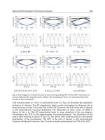
Figure 8 shows the angular deviations from the Bragg profile of the gratings formed with C
and G having bis(glycidyl ether) and bis(cyclohexene oxide), respectively, at constant
concentration of E7 (10 wt %) [DPHA : NVP: (C or G) = 50: 10: 40 relative wt%]. The angular
shifts from the Bragg matching condition (0 degree) at both positions of diffracted R and S
beams indicates the extent of volume shrinkage of the gratings. Grating prepared from the
recording solution containing only radically polymerizable compounds [DPHA : NVP = 50:
50 in relative wt%] was used as the reference.
Angular Selectivity (degree)
-6 -4 -2 0 2 4 6
Normalized Diffraction Efficiency (a.u.)
0.0
0.2
0.4
0.6
0.8
1.0
DPHA:NVP
=50:50 wt%
C
G
Angular Selectivity (degree)
-6 -4 -2 0 2 4 6
Normalized Diffraction Efficiency (a.u.)
0.0
0.2
0.4
0.6
0.8
1.0
DPHA:NVP
=50:50 wt%
C
G
(a) (b)
Fig. 8. Angular deviation from the Bragg profile for the gratings formed with C and G
[DPHA: NVP : (C or G) = 50: 10: 40 relative wt %] detected by (a) diffracted S beam, and (b)
diffracted R beam.
As shown in Figure 8, gratings formed with G having bis(cyclohexene oxide) showed
smaller deviation from Bragg matching condition than gratings formed with C having
bis(glycidyl ether) for both diffracted R and S beams. The diffraction efficiency after
overnight was only slightly changed, which indicated the volume shrinkage after overnight
was negligible.
Diffraction efficiency, angular deviation, and volume shrinkage of each system were
summarized in Table 1.
Gratings formed with only radically polymerizable multifunctional acrylate (DPHA: NVP =
50:50 relative wt %) showed the largest angle deviation, and the largest volume shrinkage of
10.3% as is well known. Such volume shrinkage could be reduced by combining the ring-
High Performance Holographic Polymer Dispersed Liquid Crystal Systems Formed
with the Siloxane-containing Derivatives and Their Applications on Electro-optics
605
opening cross-linkable monomers. Especially, bis(cyclohexene oxide)s were effective to
reduce the volume shrinkage (5.6 %), probably due to its cyclic structure, although their
diffraction efficiency was lower than those formed with bis(glycidyl ether)s.
Angular deviation of
diffracted
Recording
solution
Diffraction
efficiency (%)a
S beam
(degree)
R beam
(degree)
ϕ’
Degree of volume
shrinkage (%)
DPHA: NVP
=50:50 wt %
2 1.8 1.35 14.42 10.3
DPHA: NVP : C
= 50: 10: 40 wt %
47 1.2 1.1 14.85 7.5
DPHA: NVP: G
= 50:10:40 wt %
29 0.7 1.0 15.15 5.6
DPHA: NVP : D
= 50: 10: 40 wt %
54 0.83 0.76 15.21 5.2
DPHA: NVP: H
= 50:10:40 wt %
31 0.66 0.70 15.32 4.5
Table 1. Deviations from Bragg angle of diffracted S and R beams (degree) and degree of
volume shrinkage and diffraction efficiency determined by S beama.
The shrinkage effect could be caused by mechanical reduction of the grating pitch and a real
time change in refractive index of the irradiated mixture. Which factor is playing a major
role is not clear at present. Distinction of these factors will be a future problem.
One of the possible reasons for small volume shrinkage is the effective formation of IPN
structure in the grating in the recording system DPHA : NVP : G = 50: 10: 40 relative wt %.
The balance between the formation of initial cross-linking of DPHA and following cross-
linking by G might be proper to produce effective IPN structure.
Good evidence for these was shown in Figure 9 of SEM morphologies.
Figure 9 (a) and (c) show clearly phase-separated polymer layers after the treatment with
methanol, which means almost perfect phase separation between polymer rich layers and E7
rich layers. Cross-sectional and surface views of the sample could be observed. When 20 wt
% E7 was used, a little incompletely phase separated E7 layers were shown in Figure 9 (d),
although much higher E7 was phase separated than the case of 5 wt % E7 [Figure 9 (b)].
Grating spacing was close to the calculated value from the composition of recording
solution for the grating prepared with 5 wt % E7.
3.3 Angular selectivity
When the multiplex hologram recording is required, it is necessary to know the angular
selectivity. The smaller the value, the more multiplex data or gratings can be recorded [47-49].
Angular selectivity (Δθ
ang
) is defined by Kogelnik’s coupled wave theory as follows [50]:
22
1
2sin cos
ang
n
nT
λ
θ
θθ
⎡
⎤
Δ
⎛⎞ ⎛ ⎞
⎢
⎥
Δ= −
⎜⎟ ⎜ ⎟
⎢
⎥
⎝⎠ ⎝ ⎠
⎣
⎦
(2)
Advances in Lasers and Electro Optics
606
(a) (b)
(c) (d)
Fig. 9. SEM morphologies of gratings formed with H, TMPTA and various concentration of
E7 [TMPTA : NVP: H = 50: 10: 40 relative wt %] (a) 5 wt %, (b) 5 wt %, ×60K, (c) 20 wt %,
and (d) 20 wt %, ×60K.
where n is the average refractive index of recording solution, θ is the internal incident beam
angle, T is the thickness of the hologram, λ is the recording wavelength, and n is the
modulation of refractive index of the recording solution after recording.
Angular selectivity of our samples were similar, irrespective of the structures of epoxides
(about 4˚) as typically shown in Figure 10. Solid line represents the simulated theory values
according to the Kogelnik’s coupled wave theory.
G. Montemezzani group reported that the use of Kogelnik’s expression assuming fully
symmetric beam geometries in highly birefringent materials such as LC leads to a large error
[51]. Our experimental data showed only a little deviation from the theoretical values by the
Kogelnik’s coupled wave theory. This maybe attributed to the slight thickness reduction by
small volume shrinkage still existing. The role of both factors should be clarified in the
future.
High Performance Holographic Polymer Dispersed Liquid Crystal Systems Formed
with the Siloxane-containing Derivatives and Their Applications on Electro-optics
607
Angular Selectivity (degree)
-10 -5 0 5 10
Normalized Diffraction Efficiency
0.0
0.1
0.2
0.3
0.4
0.5
0.6
0.7
0.8
0.9
1.0
Theory
Experiment
Fig. 10. Angular selectivity of gratings formed with H , TMPTA, and 5 wt % E7 [TMPTA :
NVP : H = 50: 10: 40 relative wt %].
3.4 Effectiveness of M
M
-TMOS on formation of holographic gratings
As a preliminary experiment, M
M
-TMS and M
M
-TMOS were compared as a diluent for the
polymer matrix component (totally 65 wt%, TMPTA : M
M
-TMS, or M
M
-TMOS : NVP = 10 :
80 : 10 in wt%, average double bond functionality = 1.1 on mole base), together with 35wt%
LC of TL203. As shown in Figure 11 gratings could not be formed with M
M
-TMS even with
30 min irradiation of light, because of the low average functionality of the polymerization
system. G. P. Crawford reported that HPDLC gratings made with monomer mixtures with
average double bond functionality less than 1.3 were mechanically very weak[52]. In
general, it is difficult to form holographic gratings with low concentration of multi-
functional acrylate (average double bond functionality < 1.2) by dilution with mono-
functional component in radical polymerization.
Dramatic enhancing in the diffraction efficiency to about 86% (induction period of 144 sec)
was observed in case of M
M
-TMOS, even with only 10 wt% TMPTA by using 0.2 wt% KC
and 2wt% DPI. Only trimethoxysilyl and trimethylsilyl parts are different in these two
formulations. Hydrolysis of trimethoxysilyl group by moisture and following condensation
seems responsible for the increased diffraction efficiency.
Effects of Alkyl and Spacer Groups in ω-Methacryloxyalkyltrialkoxysilanes on the
Formation and Performance of Gratings
In order to systematically study the influence of alkyl group and spacer group of ω-
methacryloxyalkyltrialkoxysilanes on the formation and performance of the formed
gratings, their chemical structures were modified as shown in Figure1. The relative
concentration was set as TMPTA : ω-methacryloxyalkyltrialkoxysilane : NVP = 10 : 80 : 10
wt% to clearly extract the effects of hydrolysis-condensation of trialkoxysilyl group on the
formation of the gratings and the performance of the formed gratings.