15 2005 2006 toyota hilux factory service manual clutch system he thong ly hop
Bạn đang xem bản rút gọn của tài liệu. Xem và tải ngay bản đầy đủ của tài liệu tại đây (2.78 MB, 57 trang )
CL–10
CLUTCH – CLUTCH PEDAL
INSTALLATION
1.
INSTALL CLUTCH PEDAL NO.1 CUSHION
(a) Install the No. 1 cushion onto the clutch pedal.
2.
INSTALL CLUTCH PEDAL SHAFT COLLAR
(a) Apply MP grease to the clutch pedal shaft collar.
(b) Install the clutch pedal shaft collar onto the clutch
pedal.
3.
INSTALL CLUTCH PEDAL BUSH
(a) Apply MP grease to 2 new bushes.
(b) Install the 2 bushes onto the clutch pedal.
4.
INSTALL CLUTCH PEDAL PAD
5.
INSTALL CLUTCH PEDAL SPRING HOLDER
(a) Apply MP grease to the contact surface of the clutch
pedal spring holder.
(b) Install the clutch pedal spring holder.
6.
INSTALL CLUTCH PEDAL SUB-ASSEMBLY
(a) Install the clutch pedal onto the clutch pedal support
with the bolt and nut.
Torque: 34 N*m (347 kgf*cm, 25 ft.*lbf)
HINT:
Install the bolt from the left side of the vehicle.
CL
MP grease
F051531E01
MP grease
F050815E01
MP grease
F051833E01
F050814
CLUTCH – CLUTCH PEDAL
MP grease
F050817E01
CL–11
7.
INSTALL TURN OVER SPRING SEAT COMPRESSION
SPRING
(a) Apply MP grease to the contact surfaces of the
spring holder, clutch pedal and spring.
(b) Install the spring onto the clutch pedal and spring
holder.
8.
INSTALL CLUTCH MASTER CYLINDER ASSEMBLY
(See page CL-12)
9.
BLEED BRAKE LINE (w/o VSC)
10. BLEED CLUTCH PIPE LINE
11. INSPECT AND ADJUST CLUTCH PEDAL SUBASSEMBLY (See page CL-6)
12. CHECK BRAKE FLUID LEAKAGE (w/o VSC)
13. CHECK FOR CLUTCH FLUID LEAKAGE
14. CHECK FLUID LEVEL IN RESERVOIR
CL
CL–12
CLUTCH – CLUTCH MASTER CYLINDER
(c) Remove the nut and clutch start switch from the
clutch pedal support.
CL
F050810
(d) Remove the 2 bolts, then remove the clutch master
cylinder.
F050811
INSTALLATION
1.
INSTALL CLUTCH MASTER CYLINDER ASSEMBLY
(a) Install the clutch master cylinder with the 2 bolts.
Torque: 16 N*m (158 kgf*cm, 11 ft.*lbf)
(b) Install the clutch start switch with the nut.
Torque: 16 N*m (160 kgf*cm, 12 ft.*lbf)
F050811
(c) Using SST, connect the clutch master cylinder to 2
way tube.
SST 09023-00101
Torque: 15 N*m (155 kgf*cm, 11 ft.*lbf)
(d) Connect the clutch reservoir tube.
SST
F050809E01
CLUTCH – CLUTCH MASTER CYLINDER
2.
INSTALL CLUTCH PEDAL WITH CLUTCH MASTER
CYLINDER
(a) Install the clutch pedal with clutch master cylinder
onto the vehicle with the 2 nuts and bolt.
Torque: 14 N*m (145 kgf*cm, 10 ft.*lbf) for nut
24 N*m (245 kgf*cm, 18 ft.*lbf) for bolt
(b) Connect the clutch start switch connector.
3.
CONNECT DRIVER SIDE JUNCTION BLOCK
4.
INSTALL LOWER NO. 1 INSTRUMENT PANEL FINISH
PANEL (See page IP-22)
5.
INSTALL COWL SIDE TRIM BOARD LH
6.
INSTALL FRONT DOOR SCUFF PLATE LH
7.
CONNECT CLUTCH MASTER CYLINDER TO
FLEXIBLE HOSE TUBE
(a) Using SST, connect the flexible hose tube.
SST 09023-00101
Torque: 15 N*m (155 kgf*cm, 11 ft.*lbf)
8.
CONNECT CLUTCH RESERVOIR TUBE
9.
BLEED BRAKE LINE (w/o VSC)
F050808
SST
CL–13
10. BLEED CLUTCH PIPE LINE
F050807E01
11. INSPECT AND ADJUST CLUTCH PEDAL SUBASSEMBLY (See page CL-6)
12. CHECK BRAKE FLUID LEAKAGE (w/o VSC)
13. CHECK FOR CLUTCH FLUID LEAKAGE
14. CHECK FLUID LEVEL IN RESERVOIR
CL
CL–16
CLUTCH – CLUTCH RELEASE CYLINDER (for R155)
DISASSEMBLY
1.
REMOVE CLUTCH RELEASE CYLINDER KIT
(a) Remove the boot from the cylinder body.
(b) Remove the push rod from the cylinder body.
(c) Using compressed air, remove the piston together
with the spring from the cylinder.
NOTICE:
Be careful not to damage the inside of the
cylinder body.
(d) Remove the bleeder plug cap from the bleeder plug.
CL
2.
F051056
REMOVE RELEASE CYLINDER BLEEDER PLUG
CLUTCH – CLUTCH RELEASE CYLINDER (for R155)
CL–17
REASSEMBLY
1.
INSTALL RELEASE CYLINDER BLEEDER PLUG
Torque: 11 N*m (110 kgf*cm, 8.0 ft.*lbf)
2.
INSTALL CLUTCH RELEASE CYLINDER KIT
(a) Install the bleeder plug cap onto the bleeder plug.
(b) Install the spring onto the cylinder body.
(c) Apply lithium soap base glycol grease to the
portions shown in the illustration.
(d) Install the piston onto the cylinder body.
NOTICE:
Be careful not to damage the inside of the
cylinder body.
(e) Install the push rod into the cylinder body.
(f) Install the boot onto the cylinder body.
CL00672
INSTALLATION
1.
INSTALL CLUTCH RELEASE CYLINDER ASSEMBLY
(a) Install the clutch release cylinder with the 2 bolts.
Torque: 12 N*m (120 kgf*cm, 8.7 ft.*lbf)
2.
CONNECT CLUTCH RELEASE CYLINDER TO
FLEXIBLE HOSE TUBE
(a) Using SST, connect the flexible hose tube.
SST 09023-00101
Torque: 15 N*m (155 kgf*cm, 11 ft.*lbf)
3.
BLEED CLUTCH PIPE LINE
(a) Fill the brake reservoir tank with brake fluid and
bleed the clutch system.
Torque: 11 N*m (110 kgf*cm, 8.0 ft.*lbf)
4.
CHECK FOR CLUTCH FLUID LEAKAGE
F051051E01
SST
F051084E01
CL
CLUTCH – CLUTCH RELEASE CYLINDER (for R155F)
CL–19
DISASSEMBLY
1.
REMOVE CLUTCH RELEASE CYLINDER KIT
(a) Remove the boot from the cylinder body.
(b) Remove the push rod from the cylinder body.
(c) Using compressed air, remove the piston together
with the spring from the cylinder.
NOTICE:
Be careful not to damage the inside of the
cylinder body.
(d) Remove the bleeder plug cap from the bleeder plug.
2.
F051056
REMOVE RELEASE CYLINDER BLEEDER PLUG
CL
CL–20
CLUTCH – CLUTCH RELEASE CYLINDER (for R155F)
REASSEMBLY
1.
INSTALL RELEASE CYLINDER BLEEDER PLUG
Torque: 11 N*m (110 kgf*cm, 8.0 ft.*lbf)
2.
INSTALL CLUTCH RELEASE CYLINDER KIT
(a) Install the bleeder plug cap onto the bleeder plug.
(b) Install the spring onto the cylinder body.
CL
(c) Apply lithium soap base glycol grease to the
portions shown in the illustration.
(d) Install the piston onto the cylinder body.
NOTICE:
Be careful not to damage the inside of the
cylinder body.
(e) Install the push rod into the cylinder body.
(f) Install the boot onto the cylinder body.
CL00672
INSTALLATION
1.
INSTALL CLUTCH RELEASE CYLINDER ASSEMBLY
(a) Install the clutch release cylinder with the 2 bolts.
Torque: 12 N*m (120 kgf*cm, 8.7 ft.*lbf)
2.
CONNECT CLUTCH RELEASE CYLINDER TO
FLEXIBLE HOSE TUBE
(a) Using SST, connect the flexible hose tube.
SST 09023-00101
3.
BLEED CLUTCH PIPE LINE
(a) Fill the brake reservoir tank with brake fluid and
bleed the clutch system.
Torque: 11 N*m (110 kgf*cm, 8.0 ft.*lbf)
4.
CHECK FOR CLUTCH FLUID LEAKAGE
F051051E01
SST
F051084E01
CL–22
CLUTCH – CLUTCH RELEASE CYLINDER (for RA60)
DISASSEMBLY
1.
REMOVE CLUTCH RELEASE CYLINDER KIT
(a) Remove the boot from the cylinder body.
(b) Remove the push rod from the cylinder body.
(c) Using compressed air, remove the piston together
with the spring from the cylinder.
NOTICE:
Be careful not to damage the inside of the
cylinder body.
(d) Remove the bleeder plug cap from the bleeder plug.
CL
2.
F051056
REMOVE RELEASE CYLINDER BLEEDER PLUG
CLUTCH – CLUTCH RELEASE CYLINDER (for RA60)
CL–23
REASSEMBLY
1.
INSTALL RELEASE CYLINDER BLEEDER PLUG
Torque: 11 N*m (110 kgf*cm, 8.0 ft.*lbf)
2.
INSTALL CLUTCH RELEASE CYLINDER KIT
(a) Install the bleeder plug cap onto the bleeder plug.
(b) Install the spring onto the cylinder body.
(c) Apply lithium soap base glycol grease to the
portions shown in the illustration.
(d) Install the piston onto the cylinder body.
NOTICE:
Be careful not to damage the inside of the
cylinder body.
(e) Install the push rod into the cylinder body.
(f) Install the boot onto the cylinder body.
CL00672
INSTALLATION
1.
INSTALL CLUTCH RELEASE CYLINDER ASSEMBLY
(a) Install the clutch release cylinder with the 2 bolts.
Torque: 12 N*m (120 kgf*cm, 8.7 ft.*lbf)
2.
CONNECT CLUTCH RELEASE CYLINDER TO
FLEXIBLE HOSE TUBE
(a) Using SST, connect the flexible hose tube.
SST 09023-00101
Torque: 15 N*m (155 kgf*cm, 11 ft.*lbf)
(b) Install the clutch line bracket.
Torque: 12 N*m (120 kgf*cm, 8.7 ft.*lbf)
3.
BLEED CLUTCH PIPE LINE
(a) Fill the brake reservoir tank with brake fluid and
bleed the clutch system.
Torque: 11 N*m (110 kgf*cm, 8.0 ft.*lbf)
4.
CHECK FOR CLUTCH FLUID LEAKAGE
5.
INSTALL NO. 1 CLUTCH HOUSING COVER
(a) Install the clutch housing cover No. 1 with the 3
bolts.
Torque: 12 N*m (120 kgf*cm, 8.7 ft.*lbf)
F050800
SST
F050799E01
F050796
CL
CLUTCH – CLUTCH UNIT (for R155)
CL–33
INSTALLATION
1.
F050779
INSTALL INPUT SHAFT BEARING
(a) Using SST and a hammer, install the input shaft
bearing.
SST 09304-30012
HINT:
After assembling the input shaft bearing to the hub,
make sure that it rotates smoothly.
(b) Install 4 new bolts.
Torque: 27 N*m (270 kgf*cm, 20 ft.*lbf)
(c) Mark each bolt with paint as shown in the
illustration.
(d) Retighten each bolt by 90°.
(e) Check that the mark on each bolt is at a 90° angle
from its original position.
A059817
2.
INSPECT INPUT SHAFT BEARING
(a) Turn the bearing by hand while applying force in the
rotation direction.
If the bearing is stuck or difficult to turn, replace the
input shaft bearing.
HINT:
The bearing is permanently lubricated and requires
no cleaning or lubrication.
3.
INSTALL CLUTCH DISC ASSEMBLY
(a) Insert SST into the clutch disc assembly, then insert
them into the flywheel sub-assembly.
SST 09301-00210
NOTICE:
Take care not to insert clutch disc assembly in
the wrong orientation.
4.
INSTALL CLUTCH COVER ASSEMBLY
(a) Align the matchmarks on the clutch cover assembly
and flywheel sub-assembly.
(b) Tighten the 6 bolts, in the order shown in the
illustration, starting with the bolt located near the
knock pin on the top.
Torque: 19 N*m (195 kgf*cm, 14 ft.*lbf)
HINT:
• Following the order in the illustration, uniformly
tighten the bolts.
F050365
F050780
7
1 (Provisionally) 4
3
6
Matchmarks
5
2
F050781E01
CL
CL–34
CLUTCH – CLUTCH UNIT (for R155)
• Move SST up and down, right and left gently
after checking that the disc is in the center, and
tighten the bolts.
5.
INSPECT AND ADJUST CLUTCH COVER ASSEMBLY
(a) Using a dial indicator with roller instrument, check
the diaphragm spring tip alignment.
Maximum non-alignment:
0.5 mm (0.020 in.)
If the alignment is not as specified, adjust the
diaphragm spring tip alignment using SST.
SST 09333-00013
6.
INSTALL RELEASE FORK SUPPORT
(a) Install the release fork support onto the transaxle
assembly.
Torque: 47 N*m (479 kgf*cm, 35 ft.*lbf)
7.
INSTALL RELEASE BEARING HUB CLIP
8.
INSTALL CLUTCH RELEASE FORK SUB-ASSEMBLY
(a) Apply release hub grease to the release fork and
release bearing assembly contact surfaces, release
fork and push rod contact surface and release fork
pivot point.
Sealant:
Part No. 08887-01806, RELEASE HUB GREASE
or equivalent
(b) Install the release fork onto the release bearing
assembly.
9.
INSTALL CLUTCH RELEASE BEARING ASSEMBLY
(a) Apply clutch spline grease to the input shaft spline.
Sealant:
Part No. 08887-01706, CLUTCH SPLINE
GREASE or equivalent
(b) Install the bearing onto the release fork, and then
install them onto the transaxle assembly.
NOTICE:
After installation, move the fork forward and
backward to check that the release bearing
slides smoothly.
CL
F050782
Release hub grease
D027398E01
10. INSTALL CLUTCH RELEASE FORK BOOT
11. INSTALL MANUAL TRANSMISSION UNIT ASSEMBLY
(See page MT-9)
CL–38
CLUTCH – CLUTCH UNIT (for R155F)
INSTALLATION
1.
CL
F050779
INSTALL INPUT SHAFT BEARING
(a) Using SST and a hammer, install the input shaft
bearing.
SST 09304-30012
HINT:
After assembling the input shaft bearing to the hub,
make sure that it rotates smoothly.
(b) Install 4 new bolts.
Torque: 27 N*m (270 kgf*cm, 20 ft.*lbf)
(c) Mark each bolt with paint as shown in the
illustration.
(d) Retighten each bolt by 90°.
(e) Check that the mark on each bolt is at a 90° angle
from its original position.
A059817
2.
INSPECT INPUT SHAFT BEARING
(a) Turn the bearing by hand while applying force in the
rotation direction.
If the bearing is stuck or difficult to turn, replace the
input shaft bearing.
HINT:
The bearing is permanently lubricated and requires
no cleaning or lubrication.
3.
INSTALL CLUTCH DISC ASSEMBLY
(a) Insert SST into the clutch disc assembly, then insert
them into the flywheel sub-assembly.
SST 09301-00210
NOTICE:
Take care not to insert clutch disc assembly in
the wrong orientation.
4.
INSTALL CLUTCH COVER ASSEMBLY
(a) Align the matchmarks on the clutch cover assembly
and flywheel sub-assembly.
(b) Tighten the 6 bolts, in the order shown in the
illustration, starting with the bolt located near the
knock pin on the top.
Torque: 19 N*m (195 kgf*cm, 14 ft.*lbf)
HINT:
• Following the order in the illustration, uniformly
tighten the bolts.
F050365
F050780
7
1 (Provisionally) 4
3
6
Matchmarks
5
2
F050781E01
CLUTCH – CLUTCH UNIT (for R155F)
CL–39
• Move SST up and down, right and left gently
after checking that the disc is in the center, and
tighten the bolts.
5.
INSPECT AND ADJUST CLUTCH COVER ASSEMBLY
(a) Using a dial indicator with roller instrument, check
the diaphragm spring tip alignment.
Maximum non-alignment:
0.5 mm (0.020 in.)
If the alignment is not as specified, adjust the
diaphragm spring tip alignment using SST.
SST 09333-00013
6.
INSTALL RELEASE FORK SUPPORT
(a) Install the release fork support onto the transaxle
assembly.
Torque: 47 N*m (479 kgf*cm, 35 ft.*lbf)
7.
INSTALL RELEASE BEARING HUB CLIP
8.
INSTALL CLUTCH RELEASE FORK SUB-ASSEMBLY
(a) Apply release hub grease to the release fork and
release bearing assembly contact surfaces, release
fork and push rod contact surface and release fork
pivot point.
Sealant:
Part No. 08887-01806, RELEASE HUB GREASE
or equivalent
(b) Install the release fork onto the release bearing
assembly.
9.
INSTALL CLUTCH RELEASE BEARING ASSEMBLY
(a) Apply clutch spline grease to the input shaft spline.
Sealant:
Part No. 08887-01706, CLUTCH SPLINE
GREASE or equivalent
(b) Install the bearing onto the release fork, and then
install them onto the transaxle assembly.
NOTICE:
After installation, move the fork forward and
backward to check that the release bearing
slides smoothly.
F050782
Release hub grease
D027398E01
10. INSTALL CLUTCH RELEASE FORK BOOT
11. INSTALL MANUAL TRANSMISSION UNIT ASSEMBLY
(See page MT-11)
CL
CL–1
CLUTCH – CLUTCH SYSTEM (for R155)
CLUTCH SYSTEM (for R155)
PROBLEM SYMPTOMS TABLE
Use the table below to help you find the cause of the problem.
The numbers indicate the ranked order of probability of each
of the possible causes. Check each part in the order
suggested. If necessary, replace these parts.
Symptom
Clutch grabs/chatters
Clutch pedal spongy
Clutch noisy
Clutch slips
Clutch does not disengage
Suspected area
See page
1. Engine mounting (Loose)
-
2. Clutch disc (Excessive runout)
CL-31
3. Clutch disc (Oily)
CL-31
4. Clutch disc (Worn out)
CL-31
5. Clutch disc torsion rubber (Damaged)
CL-31
6. Clutch disc (Glazed)
CL-31
7. Diaphragm spring (Tip out of alignment)
CL-31
1. Clutch line (Air in line)
-
2. Release cylinder rubber (Damaged)
CL-15
1. Release bearing (Worn, dirty or damaged)
CL-31
2. Clutch disc torsion rubber (Damaged)
CL-31
1. Clutch pedal (Free play out of adjustment)
CL-6
2. Clutch disc (Oily)
CL-31
3. Clutch disc (Worn out)
CL-31
4. Diaphragm spring (Damaged)
CL-31
5. Flywheel (Distorted)
CL-31
1. Clutch pedal (Free play out of adjustment)
CL-6
2. Clutch line (Air in line)
-
3. Release cylinder cup (Damaged)
CL-15
4. Clutch disc (Out of line)
CL-31
5. Clutch disc (Runout excessive)
CL-31
6. Clutch disc (Lining broken)
CL-31
7. Clutch disc (Dirty or burned)
CL-31
8. Clutch disc (Oily)
CL-31
9. Clutch disc (Lack of spline grease)
CL-31
CL
CL–2
CLUTCH – CLUTCH SYSTEM (for R155F)
CLUTCH SYSTEM (for R155F)
PROBLEM SYMPTOMS TABLE
Use the table below to help you find the cause of the problem.
The numbers indicate the ranked order of probability of each
of the possible causes. Check each part in the order
suggested. If necessary, replace these parts.
CL
Symptom
Clutch grabs/chatters
Clutch pedal spongy
Clutch noisy
Clutch slips
Clutch does not disengage
Suspected area
See page
1. Engine mounting (Loose)
-
2. Clutch disc (Excessive runout)
CL-36
3. Clutch disc (Oily)
CL-36
4. Clutch disc (Worn out)
CL-36
5. Clutch disc torsion rubber (Damaged)
CL-36
6. Clutch disc (Glazed)
CL-36
7. Diaphragm spring (Tip out of alignment)
CL-36
1. Clutch line (Air in line)
-
2. Release cylinder rubber (Damaged)
CL-18
1. Release bearing (Worn, dirty or damaged)
CL-36
2. Clutch disc torsion rubber (Damaged)
CL-36
1. Clutch pedal (Free play out of adjustment)
CL-6
2. Clutch disc (Oily)
CL-36
3. Clutch disc (Worn out)
CL-36
4. Diaphragm spring (Damaged)
CL-36
5. Flywheel (Distorted)
CL-36
1. Clutch pedal (Free play out of adjustment)
CL-6
2. Clutch line (Air in line)
-
3. Release cylinder cup (Damaged)
CL-18
4. Clutch disc (Out of line)
CL-36
5. Clutch disc (Runout excessive)
CL-36
6. Clutch disc (Lining broken)
CL-36
7. Clutch disc (Dirty or burned)
CL-36
8. Clutch disc (Oily)
CL-36
9. Clutch disc (Lack of spline grease)
CL-36
CL–3
CLUTCH – CLUTCH SYSTEM (for RA60)
CLUTCH SYSTEM (for RA60)
PROBLEM SYMPTOMS TABLE
Use the table below to help you find the cause of the problem.
The numbers indicate the ranked order of probability of each
of the possible causes. Check each part in the order
suggested. If necessary, replace these parts.
Symptom
Clutch grabs/chatters
Clutch pedal spongy
Clutch noisy
Clutch slips
Clutch does not disengage
Suspected area
See page
1. Engine mounting (Loose)
-
2. Clutch disc (Excessive runout)
CL-41
3. Clutch disc (Oily)
CL-41
4. Clutch disc (Worn out)
CL-41
5. Clutch disc torsion rubber (Damaged)
CL-41
6. Clutch disc (Glazed)
CL-41
7. Diaphragm spring (Tip out of alignment)
CL-41
1. Clutch line (Air in line)
-
2. Release cylinder rubber (Damaged)
CL-21
1. Release bearing (Worn, dirty or damaged)
CL-41
2. Clutch disc torsion rubber (Damaged)
CL-41
1. Clutch pedal (Free play out of adjustment)
CL-6
2. Clutch disc (Oily)
CL-41
3. Clutch disc (Worn out)
CL-41
4. Diaphragm spring (Damaged)
CL-41
5. Flywheel (Distorted)
CL-41
1. Clutch pedal (Free play out of adjustment)
CL-6
2. Clutch line (Air in line)
-
3. Release cylinder cup (Damaged)
CL-21
4. Clutch disc (Out of line)
CL-41
5. Clutch disc (Runout excessive)
CL-41
6. Clutch disc (Lining broken)
CL-41
7. Clutch disc (Dirty or burned)
CL-41
8. Clutch disc (Oily)
CL-41
9. Clutch disc (Lack of spline grease)
CL-41
CL
CL–4
CLUTCH – CLUTCH SYSTEM (for RA60F)
CLUTCH SYSTEM (for RA60F)
PROBLEM SYMPTOMS TABLE
Use the table below to help you find the cause of the problem.
The numbers indicate the ranked order of probability of each
of the possible causes. Check each part in the order
suggested. If necessary, replace these parts.
CL
Symptom
Clutch grabs/chatters
Clutch pedal spongy
Clutch noisy
Clutch slips
Clutch does not disengage
Suspected area
See page
1. Engine mounting (Loose)
-
2. Clutch disc (Excessive runout)
CL-45
3. Clutch disc (Oily)
CL-45
4. Clutch disc (Worn out)
CL-45
5. Clutch disc torsion rubber (Damaged)
CL-45
6. Clutch disc (Glazed)
CL-45
7. Diaphragm spring (Tip out of alignment)
CL-45
1. Clutch line (Air in line)
-
2. Release cylinder rubber (Damaged)
CL-24
1. Release bearing (Worn, dirty or damaged)
CL-45
2. Clutch disc torsion rubber (Damaged)
CL-45
1. Clutch pedal (Free play out of adjustment)
CL-6
2. Clutch disc (Oily)
CL-45
3. Clutch disc (Worn out)
CL-45
4. Diaphragm spring (Damaged)
CL-45
5. Flywheel (Distorted)
CL-45
1. Clutch pedal (Free play out of adjustment)
CL-6
2. Clutch line (Air in line)
-
3. Release cylinder cup (Damaged)
CL-24
4. Clutch disc (Out of line)
CL-45
5. Clutch disc (Runout excessive)
CL-45
6. Clutch disc (Lining broken)
CL-45
7. Clutch disc (Dirty or burned)
CL-45
8. Clutch disc (Oily)
CL-45
9. Clutch disc (Lack of spline grease)
CL-45
CL–5
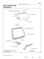
CLUTCH – CLUTCH PEDAL
CLUTCH PEDAL
CLUTCH
TRANSMISSION
COMPONENTS
CL
34 (347, 25)
CLUTCH PEDAL SPRING HOLDER
CLUTCH PEDAL SHAFT COLLAR
CLUTCH PEDAL NO.1 CUSHION
CLUTCH PEDAL BUSH
CLUTCH PEDAL BUSH
TURN OVER SPRING SEAT
COMPRESSION SPRING
CLUTCH PEDAL SUB-ASSEMBLY
CLUTCH PEDAL PAD
N*m (kgf*cm, ft*lbf) :Specified torque
Apply MP grease
C114211E01
CL–6
CLUTCH – CLUTCH PEDAL
ON-VEHICLE INSPECTION
1.
CL
Pedal Height
Adjustment
Point
Push Rod Play and
Free Play Adjustment
Point
Push Rod
Play
INSPECT AND ADJUST CLUTCH PEDAL SUBASSEMBLY
(a) Lift the floor carpet.
(b) Check that the pedal height is correct.
Pedal height from asphalt sheet:
168.5 to 178.5 mm (6.634 to 7.028 in.)
(c) Adjust the pedal height.
(1) Loosen the lock nut and turn the stopper bolt
until the height is correct. Tighten the lock nut.
Torque: 25 N*m (250 kgf*cm, 18 ft.*lbf)
(d) Check that the pedal free play and push rod play are
correct.
(1) Depress the pedal until the clutch resistance
begins to be felt.
Pedal free play:
5.0 to 15.0 mm (0.197 to 0.591 in.)
(2) Gently depress the pedal until the resistance
begins to increase a little.
Push rod play at pedal top:
1.0 to 5.0 mm (0.039 to 0.197 in.)
Pedal Height
F050836E01
Pedal Free Play
Push Rod Play
(e) Adjust the pedal free play and push rod play.
(1) Loosen the lock nut and turn the push rod until
the free play and push rod play are correct.
(2) Tighten the lock nut.
(3) After adjusting the pedal free play, check the
pedal height.
(4) Connect the air duct and install the lower finish
panel.
D031462E03
(f)
25 mm (0.98 in.) or more
Release Point
Full Stroke
End Position
CL00512E05
Check the clutch release point.
(1) Pull the parking brake lever and use wheel
chocks.
(2) Start the engine and allow it to idle.
(3) Without depressing the clutch pedal, slowly
move the shift lever into the reverse position
until the gears engage.
(4) Gradually depress the clutch pedal and
measure the stroke distance from the point that
the gear noise stops (release point) up to the
full stroke end position.
Standard distance:
25 mm (0.984 in.) or more
(From pedal stroke end position to release
point)
If the distance is not as specified, perform the
following operations.
CLUTCH – CLUTCH PEDAL
•
•
•
•
CL–7
Check the pedal height.
Check the push rod play and pedal free play.
Bleed the clutch line.
Check the clutch cover assembly and disc
assembly.
CL
CL–10
CLUTCH – CLUTCH MASTER CYLINDER
CLUTCH MASTER CYLINDER
CLUTCH
TRANSMISSION
COMPONENTS
24 (245, 18)
CL
15 (155, 11)
CLUTCH MASTER CYLINDER
TO FLEXIBLE HOSE TUBE
CLUTCH RESERVOIR
TUBE
14 (145, 10)
CLUTCH START SWITCH
16 (160, 12)
CLUTCH RESERVOIR TUBE
CLUTCH MASTER CYLINDER ASSEMBLY
16 (158, 11)
15 (155, 11)
CLUTCH MASTER CYLINDER to 2 WAY TUBE
N*m (kgf*cm, ft*lbf) :Specified torque
C114212E01
CLUTCH – CLUTCH MASTER CYLINDER
CL–11
REMOVAL
SST
1.
DRAIN CLUTCH FLUID
2.
DISCONNECT CLUTCH RESERVOIR TUBE
3.
DISCONNECT CLUTCH MASTER CYLINDER TO
FLEXIBLE HOSE TUBE
(a) Using SST, disconnect the flexible hose tube.
SST 09023-00101
4.
REMOVE FRONT DOOR SCUFF PLATE LH
5.
REMOVE COWL SIDE TRIM BOARD LH
6.
REMOVE LOWER NO. 1 INSTRUMNT PANEL FINISH
PANEL (See page IP-12)
7.
SEPARATE DRIVER SIDE JUNCTION BLOCK
8.
REMOVE CLUTCH PEDAL WITH CLUTCH MASTER
CYLINDER
(a) Disconnect the clutch start switch connector.
F050807E01
(b) Remove the 2 nuts and bolt, then remove the clutch
pedal with clutch master cylinder.
9.
REMOVE CLUTCH MASTER CYLINDER ASSEMBLY
(a) Disconnect the clutch reservoir tube.
F050808
(b) Using SST, disconnect the 2 way tube from the
clutch master cylinder.
SST 09023-00101
SST
F050809E01
CL
CL–12
CLUTCH – CLUTCH MASTER CYLINDER
(c) Remove the nut and clutch start switch from the
clutch pedal support.
CL
F050810
(d) Remove the 2 bolts, then remove the clutch master
cylinder.
F050811
INSTALLATION
1.
INSTALL CLUTCH MASTER CYLINDER ASSEMBLY
(a) Install the clutch master cylinder with the 2 bolts.
Torque: 16 N*m (158 kgf*cm, 11 ft.*lbf)
(b) Install the clutch start switch with the nut.
Torque: 16 N*m (160 kgf*cm, 12 ft.*lbf)
F050811
(c) Using SST, connect the clutch master cylinder to 2
way tube.
SST 09023-00101
Torque: 15 N*m (155 kgf*cm, 11 ft.*lbf)
(d) Connect the clutch reservoir tube.
SST
F050809E01
CL–14
CLUTCH – CLUTCH RELEASE CYLINDER (for R155)
CLUTCH RELEASE CYLINDER (for R155)
CLUTCH
TRANSMISSION
COMPONENTS
CL
RELEASE CYLINDER BLEEDER PLUG CAP
PUSH ROD
12 (120, 8.7)
11 (110, 8.0)
BOOT
RELEASE CYLINDER
BLEEDER PLUG
PISTON
SPRING
RELEASE CYLINDER BODY
15 (155, 11)
CLUTCH RELEASE CYLINDER TO FLEXIBLE HOSE TUBE
N*m (kgf*cm, ft*lbf) :Specified torque
Lithium soap base glycol grease
C114063E01