Advances in Solid-State Lasers: Development and Applicationsduration and in the end limits Part 4 doc
Bạn đang xem bản rút gọn của tài liệu. Xem và tải ngay bản đầy đủ của tài liệu tại đây (4.5 MB, 40 trang )
Advances in Solid-State Lasers: Development and Applications
112
1908-nm line. In the last part of characterisation in a free-running regime, we have measured
the beam profiles in far field in the focal plane of a 500-focal length lens. The divergence angle
was about 4.3 mrad and an estimated parameter M
2
< 1.3 for high 20-W incident pump power.
3.3 Q-switching experiments for low duty cycle pumping
For Q-switching we have used a water cooled acousto-optic modulator made of 45-mm long
fused silica, operating at a radio frequency of 40.7 MHz with a maximum power of 25 W. In
fact, that was the largest element of laser head which determined its size. It was shown in
separate experiments that for maximum RF power of the acousto-optic modulator the
diffraction efficiency was higher than 80%, diffraction angle was about 7 mrad and the
falling edge, i.e. switch off time was about 100 ns.
In the first part of the Q-switching experiments we have estimated the maximum available
output energy in free-running for which the acousto-optic modulator can hold off
oscillations for a switch on state of RF power. It should be noted that we have used a 220-
mm long cavity with Lyot’s filter inside introducing additional insertion losses. The laser
output was horizontally polarized (perpendicularly to the c-axis of YLF crystal).
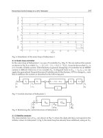
Fig. 19. Available output energy vs. incident pump energy in free running for the state of
effective operation of the active Q-switch
As was shown in Fig. 19, for the best case the output energy of 40 mJ (for incident pump
energy of 400 mJ) was the upper limit of efficient operation of the Q-switch. However, the
real limit of output energy was far lower, because of the damage threshold of the Tm:YLF
crystal facet. It was shown, that the output energy above 10 mJ corresponding
approximately to 1.5 – 2 GW/cm
2
of intracavity power density constitutes the upper limit of
available pulse energy for the safe operation in a Q-switching regime in the case of our laser
head. Thus, we can conclude that a much smaller Q-switch without water cooling will be
satisfactory for our purposes.
0 100 200 300 400 500
E
pump
[mJ]
0
10
20
30
40
50
60
E
free-runn
[mJ]
t
p
=3.3 ms, f
rep
= 100 Hz,
t
p
= 5 ms,
f
rep
= 50 Hz
t
p
= 10 ms,
f
rep
= 10 Hz
t
p
= 20 ms,
f
rep
= 10 Hz
3.5%Tm:YLF laser with AO-qswitch
L
cav
= 220 mm, R
curv
= 500 mm, T
oc
=15%
free-running
10 mJ damage threshold limit
hold off limit
Actively Q-switched Thulium Lasers
113
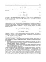
The results of measurements of pulse duration and peak power for a low duty cycle of 10%
(10 Hz of PRF and 10 ms pump duration) were shown in Fig. 20. The shortest pulse of 22-ns
duration (see Fig. 21) and 10.5 mJ energy corresponding to 0.45 MW of peak power were
demonstrated for the best case of stable output below the risk of damages to laser elements.
Fig. 20. Pulse duration, peak power vs. pump energy for Q-switching in a low 10% duty
cycle pumping regime.
Fig. 21. Oscillogram of the giant pulse of 10.5 mJ of energy.
150 200 250 300
Pump Energy [mJ]
0
30
60
90
120
150
Pulse duration [ns]
0
100
200
300
400
500
Peak Power [kW]
Tm:YLF laser
Lyot filter + AO qswitch
Advances in Solid-State Lasers: Development and Applications
114
3.4 Q-switching experiments for CW pumping
For the CW pumping regime the maximum pump power was constituted due to the thermal
lensing limit. Because of negative thermal dispersion of Tm:YLF the cavity achieves stability
limit for nearly 20-W of incident pump power.
The results of the Q-switching experiments were shown in Fig. 22, 23, and collected in Table
2. Nearly 20% slope efficiency with respect to absorbed pump energy was obtained for
high repetition frequency. The experimental results were in agreement with the numerical
model presented in p. 2.3.2
Fig. 22. Output energy vs. absorbed pump energy for different repetition periods.
f
rep
[Hz]
d.f.
P
avg
[W]
E
p
[mJ]
τ
p
[ns]
P
p
[kW]
1000 1 1.725 1.725 146 11.8
400 1 1.725 4.31 101 42.7
200 1 1.541 7.7 70 110
133 1 1.38 10.35 46.8 221
10 0.1 0.105 10.5 22 447
Table 2. Results of Q-switching experiments; f
rep
– pulse repetition frequency, d.f. – duty
cycle factor, P
avg
– average output power, E
p
– pulse energy, τ
p
– pulse duration, P
p
– peak
power.
The comparable pulse energies of 10 mJ (last two rows of Table 2) were achieved for both
cases of pumping. The much longer pulse duration for a case of CW pumping was caused
0 20 40 60 80 100 120
Absorbed Pump Energy [mJ]
0
2
4
6
8
10
12
Output Energy [ mJ ]
t
rep
=7.5 ms,
η
=0.165
t
rep
= 5 ms,
η
=0.183
t
rep
=2.5 ms,
η
=0.195
t
rep
= 1 ms,
η
=0.217
L
cav
= 220
η
abs
= 0.75 - 0.8
3.5% Tm:YLF,
φ
3x10
R
curv
=500, Toc = 0.15
AO-Q-switched Tm:YLF laser
Actively Q-switched Thulium Lasers
115
by the combined effect of an increase in reabsorption and additional diffraction loss (see
p. 2.3.2). Please note, that maximum available pulse energy was limited in both cases by
reaching the damage thresholds of the rod facet or rear mirror.
6 8 10 12 14 16
Absorbed Pump Power [W]
0.05
0.10
0.15
0.20
0.25
Output Peak Power [MW]
AO-Q-switched Tm:YLF laser
R
curv
=500, Toc = 0.15
3.5% Tm:YLF,
φ
3x10
η
abs
= 0.75 - 0.8
L
cav
= 220
t
rep
= 7.5 ms
t
rep
= 5 ms
t
rep
= 2.5 ms
t
rep
= 1 ms
Fig. 23. Output peak power vs. absorbed pump power for different repetition periods.
4. Conclusions
The analytical models of quasi-three-level lasers operating in free running and Q-switching
regimes were presented. In both cases appropriate formulae enabling the optimization of
such lasers were given and analysed. The numerical model of a quasi-three-level laser
operating in a Q-switching regime including additional pump dependent losses, was
elaborated to explain the properties of the developed actively Q-switched laser. The main
difference in analysis of Q-switching in a quasi-three-level laser (compared to a four-level
laser) consists of the effect of temperature on giant pulse parameters. Because of increase in
temperature with pump power, the net inversion, additional reabsorption and diffraction
losses significantly influence available pulse energy, peak power and pulse duration. The all
above mentioned effects result in the fact, that giant pulse is generated for a considerable
level of losses dependent on effective average heat power dissipated in the gain medium.
The results of numerical modelling were confirmed in the experiments.
To compare models with experiments we have presented the results of investigations of an
efficient Tm:YLF laser end-pumped by 30-W fiber coupled laser diode bar. The incident
pump density exceeded above 5 times the saturation pump density, thus the drawbacks of
the quasi-three-level scheme have been mitigated. We have obtained the best output
characteristics (slope and maximum power) for out-coupling losses of 20% evidencing the
high roundtrip gain for maximum pump power. Above 7-W of output power for incident
Advances in Solid-State Lasers: Development and Applications
116
26-W pump power in free running regime was achieved in the best case for a short 70-mm
cavity. Above 3 W of output power was demonstrated for CW pumping for an elongated
220-mm cavity. The divergence angle was about 4.3 mrad and estimated parameter M
2
< 1.3.
To improve the output characteristics in a free running regime, the optimisation of pump
size in the gain medium, application of a longer rod and optimised cavity design should be
applied.
For the free-running and Q-switching regimes the output spectrum was centred at 1908-nm
with linewidth less than 6 nm. For tuning the Lyot’s filter consisting of 2 quartz plates was
deployed. The tuning range of 1845-1935 nm with less than 1-nm linewidth was
demonstrated for the free-running regime. For the Q-switching regime the contrast of a
deployed birefringent filter was too low to prevent oscillation on the strongest 1908-nm
linewidth.
In the experiments on active Q-switching by means of an acousto-optic modulator, up to 10-
mJ output energy was demonstrated. Output energy was limited by damage of the laser
elements. Nearly 0.5 MW peak power with pulse durations of 22 ns was achieved for a 10-
Hz repetition rate with 10% duty cycle of the pumping regime. The 1.7-W of average power
with 12 kW peak power and 1000 Hz repetition rate was demonstrated for the CW pumping
regime. The developed laser could constitute the basis for development of the tunable, Q-
switched laser source operating at a 2-
μm wavelength. Moreover, it could be used as a
pump source for Ho:YAG and Cr:ZnSe lasers operating in a gain switching regime for the
longer ( > 2
μm) wavelengths.
5. Acknowledgments
This work was supported by the Polish Ministry of Science and Higher Education under
projects 0T00A00330, NN515 423033, NN515 414834, NN515 345036.
6. References
Barnes, N., & De Young, R. (2009). Tm:germanate Fiber Laser for Planetary Water Vapor
Atmospheric Profiling. The Conference on Lasers and Electro-Optics (CLEO)/The
International Quantum Electronics Conference (IQEC) (Optical Society of America,
Washington, DC, 2009 (p. JWA60). Optical Society of America, Washington, DC,
2009
Barry, D., Parlange, J., Li, L., Prommer, H., Cunningham, C., & Stagnitti, F. (2000). Analytical
approximation for eal values of the LambertW function. Math and Computers in
Simulation , Vol. 53, pp. 4-14
Beach, R. (1996). CW Theory of quasi-three-level end-pumped laser oscillators. Optics
Communications , Vol. 123, pp. 385-393
Bourdet, G. (2001). New evaluation of ytterbium-doped materials for CW laser applications.
Optics Communications , Vol. 198, pp. 411-417
Bourdet, G. (2000). Theoretical investigation of quasi-three-level longitudinally pumped
continuous wave lasers. Applied Optics , Vol. 39, pp. 966-971.
Budni, P., Lemons, M., Mosto, J., & Chicklis, E. (2000). High-Power/High-Brightness Diode-
Pumped 1.9-
μm Thulium and Resonantly Pumped 2.1-μm Holmium Lasers IEEE J.
Sel. Top. Quant. Electron, Vol. 6, No. 4, pp. 629-634
Actively Q-switched Thulium Lasers
117
Chen, Y F. (1999). Design Criteria for Concentration Optimization in Scaling Diode End-
Pumped lasers to High Powers: Influence of Thermal Fracture. IEEE Journal of
Quantum Electronics, Vol. 35, pp. 234-239
Clarkson, W., Shen, D., & Sabu, J. (2006). High-power fiber-bulk hybrid lasers. Proceedings
SPIE, Vol. 6100, pp. 61000A-1-13
Degnan, J. (1989). Theory of optimally coupled Q-switched laser. IEEE Journal of Quantum
Electronics , Vol. 25, pp. 214-220
Dergachev, A., Wall, K., & Moulton, P. (2002). A CW Side-pumped Tm:YLF Laser. OSA
TOPS, Advanced Solid State Lasers, ed. M.E. Ferman L.R. Marshall, Vol. 68, pp. 343-346
Eichhorn, M. (2008). First investigations on an Er
3+
:YAG SSHCL. Appl. Phys. B , Vol. 93, pp.
817-822
Eichhorn, M. (2008). High-Power Resonantly Diode-Pumped CW Er
3+
:YAG Laser. Appl.
Phys. B , Vol. 93, pp. 773-778
Eichhorn, M. (2008). Quasi-three-level solid-sate lasers in the near and mid infrared based
on trivalent rare earth ions. Appl Phys B , Vol. 93, pp. 269-316
Eichhorn, M., & Jackson, S. (2008). High-pulse-energy, actively Q-switched Tm
3+
-doped
silica 2 m fiber laser pumped at 792 nm. Optics Letters , Vol. 32, pp. 2780-2782
Eichhorn, M., & Jackson, S. (2009). High-pulse-energy, actively Q-switched Tm
3+
,Ho
3+
-
codoped silica 2 m fiber laser. Optics Letters , Vol. 33, pp. 1044-1046
Gaponenko, M., Denisov, I., Kisel, V., Malyarevich, A., Zhilin, A., Onushchenko, A., et al.
(2008). Diode-pumped Tm:KY(WO
4
)
2
laser passively Q-switched with PbS-doped
glass. Appl Phys B , Vol. 93, pp. 787-791
Gapontsev, D., Platonov, N., Meleshkevich, M., Drozhzhin, A., & Sergeev, V. (2007). 415W
single-mode CW thulium fiber laser in all-fiber format. CLEO Europe, 2007, paper.
CP2-3-THU
Godard, A. (2007). Infrared (2-12 μm) solid-state laser sources: a review. C.R. Physique , Vol.
8, pp. 1100-1128
Gorajek, L., Jabczyński, J.K. , Zendzian, W., Kwiatkowski, J., Jelinkova, H., Sulc, J., et al.
(2009). High repetition rate, tunable, Q-switched, diode pumped Tm:YLF laser.
Opto-Electronics Rev., Vol. 6, pp. 23-35
Grace, E., New, G., & Franch, P. (2001). Simple ABCD matrix treatment for transversely
varying saturable gain. Optics Express , Vol. 26, pp. 1776-1778
Honea, E., Beach, R., Sutton, S., Speth, J., Mitchell, S., Skidmore, J., et al. (1997). 115-W
Tm:YAG Diode-Pumped Solid-State Laser. IEEE Journal of Quantum Electronics,
Vol. 33, pp. 1592-1600.
Huber, G., Duczynski, E., & Peterman, K. (1988). Laser pumping of Ho—Tm-, Er- doped
garnet laser at room temperature. IEEE Journal of Quantum Electronics , Vol. 24, pp.
920-923.
Jabczyński, J., Gorajek, L., Zendzian, W., Kwiatkowski, J., Jelinkova, H., Sulc, J., et al. (2009).
High repetition rate, high peak power, diode pumped Tm:YLF laser. Laser Phys.
Letters , Vol. 6, pp. 109-112
Jabczyński, J., Kwiatkowski, J., & Zendzian, W. (2003). Modeling of beam width in passively
Q-switched end-pumped laser. Optics Express , Vol. 11, pp. .552-559
Jabczyński, J., Zendzian, W., Kwiatkowski, J., Jelinkova, H., Sulc, J., & Nemec, M. (2007).
Actively Q-switched diode pumped thulium laser. Laser Phys. Letters , Vol. 4, pp.
863-867
Advances in Solid-State Lasers: Development and Applications
118
Koechner, W. (1996). Solid-State Laser Engineering. Springer Verlag, ISBN 3-540-60237-2,
Berlin
Kudryashov, I., Katsnelson, A., Ter-Gabrielyan, N., & Dubinskii, M. (2009). Room
Temperature Power Scalability of the Diode-Pumped Er:YAG Eye-Safe Laser.
CLEO-Baltimore, paper CWA2
Lim, C., & Izawa, Y. (2002). Modeling of End-Pumped CW Quasi-Three-Lvele Lasers. IEEE
Journal of Quantum Electronics , Vol. 38, pp. 306-311
Lisiecki, R., Solarz, P., Dominiak-Dzik, G., Ryba-Romanowski, W., Sobczyk, M., Cerny, P., et
al. (2006). Comparative optical study of thulium-doped YVO
4
, GdVO
4
, and LuVO
4
single crystals. Phys. Rev. B , Vol. 74, pp. 035103.
McComb, T., Shah, L., Sims, A., Sudesh, V., Szilagyi, J., & Richardson, ,. M. (2009). Tunable
Thulium Fiber Laser System for Atmospheric Propagation Experiments. Conference
on Lasers and Electro-Optics (CLEO)/The International Quantum Electronics Conference
(IQEC) (Optical Society of America, Washington, DC, paper CthR5.
Mirov, S., Fedorov, V., Moskalev, I., & Martyshkin, D. (2007). Recent Progress in Transistion-
Metal-Dped II-VI Mid-IR Lasers. IEEE Journal of Selected Topics in Quantum
Electronics , Vol. 13, pp. 810-822
Payne, S., Chase, L., Smith, L., Kway, W., & Krupke, W. (1992). Infrared Cross-Section
Measurements for Crystals Doped with Er
3+
, Tm
3+
, and Ho
3+
. IEEE Journal of
Quantum Electronics , Vol. 28, pp. 2619-2630
Rustad, G., & Stenersen, K. (1996). Modeling of Laser-Pumped Tm and Ho Lasers
Accounting for Upconversion and Ground-State Depletion. IEEE Journal of
Quantum Electronics , 32, pp. 1645-1655.
Schellhorn, M. (2008). High-power diode-pumped Tm:YLF laser. Appl. Phys. B , Vol. 91, pp.
pp. 71-74
Schellhorn, M., Ngcobo, S., & Bollig, S. (2009). High-Power Diode-Pumped Tm:YLF slab
laser. Appl. Phys. B , Vol. 94, pp. 195-198
Schellhorn, M., Eichhorn, M., Kieleck, C., & Hirth, A. (2007). High repetition rate mid-
infrared laser source. C. R. Physique , Vol. 8, pp. 1151-1161
Setzler, S., Francis, M., Young, Y., Konves, J., & Chicklis, E. (2005). Resonantly pumped
eyesafe erbium lasers. IEEE J. Sel. Top. Quant. Electron , Vol. 11, pp. 645-657
So, S., MacKenzie, J., Shepherd, D., Clarkson, W., Betterton, J., & Gorton, E. (2006). A power-
scaling strategy for longitudinally diode-pumped Tm:YLF lasers. Appl. Physics B. ,
Vol. 84, pp. 389-393
Sorokina, I., & Vodopyanov, K. (2003). Solid-State Mid-Infrared Laser Sources.: Springer
Verlag, ISBN 3-540-00621, Berlin
Zhu, X., & Jain, R. (2007). 10-W-level diode-pumped compact 2.78
μm ZBLAN fiber laser.
Opt. Letters , Vol. 32, pp. 26-28.
6
Efficient Intracavity Beam Combining of
Multiple Lasers in a Composite Cavity
Ming Lei
Department of Electronic Engineering
Tsinghua University
China
1. Introduction
High power or high energy solid-state lasers are required in many applications, but are limited
in beam quality or brightness at high pump level by thermal effects. Beam combining with two
lasers is an effective way to solve this problem and has been successfully realized in the past
(Sabourdy et al., 2002; Sabourdy et al., 2003; Qinjun et al., 2005; Eckhouse et al., 2005). In order
to get higher output energy with good beam quality, researchers often regard the two-channel
combined configuration as the elementary laser and combine an even number of elementary
lasers in a tree architecture (Sabourdy et al., 2002; Sabourdy et al., 2003; Qinjun et al., 2005).
These direct extending schemes can successfully combine 2×N channel lasers into one beam
intracavity, but the whole scaling geometry is really complicated and bulk, which bring more
difficulties for alignment among multiple branches. Besides all these additions of laser beams
are only obtained with spatial Gaussion beams(Sabourdy et al., 2002; Sabourdy et al., 2003;
Qinjun et al., 2005), which limits the output power for scaling. Using a planar interferometric
coupler, Ishaaya firstly reported intracavity beam addition of transverse multimode laser
beam distributions (Ishaaya, et al., 2004), then more than two lasers combination has also been
demonstrated (Eckhouse, et al., 2005; Eckhouse, et al., 2006). In these schems, the thick planar
interferometric coupler with a high-precision plane is the key component. But it is difficult to
fabricate this coupler, further, the intracavity loss will increase when multiple beams being
combined. In addition, most of these more than two-channel combining schemes are based on
the open-ended configuration (Sabourdy et al., 2002; Sabourdy et al., 2003; Qinjun et al., 2005;
Eckhouse et al., 2005; Eckhouse, et al., 2006; Ishaaya, et al., 2004), if the symmetries of many
branches are not well guaranteed, the loss will be unavoidably introduced from every open
end of the beam splitter or coupler, consequently resulting in instability of the whole
composite cavity. Generally speaking, these kinds of cavities are not very easy to implement at
present.
Recently, we have presented a new close-ended Four-Mirror Cavity to combine two beams
with two gain media intracavity (Ming & Mali, 2007). Base on this, in this letter, we propose a
novel and practical composite-cavity, named Six-Mirror Cavity, to combine four beams with
four gain media intracavity. This cavity is based on a close-ended configuration, which makes
the output very stable, even when multiple channels combining at the high pump level. Also,
it is not the direct extending of the two-channel scheme as the conventional strategies, the
Advances in Solid-State Lasers: Development and Applications
120
reduction of two mirrors compared with the scaling scheme shown in Ref (Ming & Mali, 2007),
makes the whole scaling configuration simple, compact and easy to implement. Moreover, it is
an approach for efficient intra-cavity beam addition of transverse multimode laser beam
distributions, possessing considerably more energy than that of Gaussian beam distributions.
The whole cavity is composed of several LD pumped laser modules. Compared to end-
pumped scheme, the diode-side-pumped configuration has a more excellent scalability to
obtain high output energy (Fujikawa et al., 1997). Several side-pumped lasers with slab and
rod media geometries were investigated. Slab geometry requires expensive slab-shaped
materials, and it is difficult to generate symmetrical beam patterns because of the
rectangular cross section of the laser medium (Golla et al., 1995). On the contrary, side-
pumped scheme by using rod laser systems can overcome the above-mentioned
shortcomings and is especially appropriate for beam combination. Therefore, here we adopt
the diode arrays side-pumped rod laser as the basic module and combine four laser
modules intracavity with a six-mirror cavity.
2. Six-mirror cavity configuration
The basic configuration for energy addition of four lasers with six-mirror cavity is
schematically presented in Fig.1. The cavity is based on close-ended resonator, which is
composed of six end mirrors M
1
-M
6
. M
1
-M
5
are flat 100% reflectors at the laser wavelength
(1064nm) and M
6
is the output mirror with 80% transmission at 1064nm. Thanks to two
50/50 beam splitters, BS, the lasers produced by each arm combine together into one beam
in the end and export from the output coupler M
6
.
Fig. 1. Schematic of the experimental setup of the six-mirror cavity. BS: beam splitter; LD:
laser diode; M
1
-M
6
: mirrors;
The whole system consists of four amplifying modules, i.e., four laser heads, arranged in the
respective branch arm. Fig.2 shows the schematic cross section of the side-pumped Nd:YAG
rod laser head. The laser rod (diameter of 5mm, length of 55mm, Nd-doping level of 1.0
at.%) is placed in a glass tube for direct water cooling. Outside the tube, a number of linear
LD arrays are located circular-symmetrically and densely around the rod, generating 808nm
laser that is directly coupled into the rod. The two end faces of the rod are AR-coated at
1064nm and wedged into 2 degree, which prevents the self-oscillation of the rod. Each
pump LD arrays is directly attached to a copper heat sink. The temperature of the pump
modules is controlled by the water flow through the copper heat sinks to regulate the
temperature of the diode lasers within an accuracy of ± 0.2°C.
Efficient Intracavity Beam Combining of Multiple Lasers in a Composite Cavity
121
Fig. 2. Schematic cross section of the side-pumped Nd:YAG rod laser head
Every laser head works in a free-running mode and the LD energy supply provides 240μs
electric pulse and 1Hz repetition rate. 1μs pulse synchronization has been set among the
four channels with the outer-trigger, so that the laser beams produced by every laser heads
can be combined temporally and spatially at the same time.
3. Experimental results and analysis
We use EPM2000 two-channel joulemeter/power meter and J50HR energy probe
(Molectron, Inc.) to measure the output energy and a laser beam analyzer (Spiricon M
2
-200)
to detect the beam quality and the intensity distribution for the combined laser and the four
individual lasers. As is illustrated in Fig.3, the output energies of the six-mirror cavity when
only one LD arrays(LD
1
,LD
2
,LD
3
or LD
4
) is pumping, and the combined energy when four
LD arrays are pumping simultaneously are shown. A single beam multimode output
exceeding 453mJ (165μs duration, 1Hz repetition rate) at 1064nm is obtained when the four
laser heads work simultaneously in the six-mirror cavity.
In order to demonstrate the improved brightness of six-mirror cavity, four Fabry-Parot
lasers with the cavity length of 31cm (same to the length of l
2
+ l
7
in Fig.4(b)) are
characterized for reference with the experimental setup shown in Fig.4(a). When the four LD
arrays, i.e. four laser heads, work at the maximum pump energy of 1.26J with 70A operating
current, the output properties in five cases are listed in Table 1 and the brightness is
calculated by the expression (Fan, 2005)
222 22
()
Xy Xy
EkE
B
M
MMM
λ
⋅
==
⋅⋅ ⋅
(1)
where
2
1/k
λ
=
(2)
The increasing output energy and the good combined beam quality are well shown in Table
1 and Fig.4. Using this six-mirror cavity, four independent elementary multimode lasers
have been successfully combined into one beam intracavity with the combination efficiency
of 90.7% (453.3/(124.7+131.2+115+128.6)=0.907), a rather high value despite the disparity
and multimode distribution among the four branch laser heads features. These results can
be explained as follows. In the laser cavity, the four elementary lasers are inter-seeds of each
other. One laser beam imprint its transverse distubution content on the other three beam
distributions. The combined laser tends to operate so that the losses are minimum.
Therefore, each of the transverse beam distribution adds with its counterpart in the other
three beams and four multimode beam distributions have similar distribution composition.
Advances in Solid-State Lasers: Development and Applications
122
Consequently four multimode beams combine intracavity successfully and considerably
higher output energy is obtained in laser system.
The brightness of the combined laser has been significantly improved more than 3 times
compared to single F-P cavity laser. Furthermore, the experiments also show that when the
pump energy is fixed, the laser output of the six-mirror cavity is stable with no change in
energy or beam quality, which shows that this cavity can withstand environmental
perturbations very well.
0.4 0.6 0.8 1.0 1.2
0
100
200
300
400
500
1.6 2.4 3.2 4.0 4.8
Pump Pulse Energy of Four LD arrays (J)
Output Enervgy (mJ)
Pump Pulse Energy of Single LD arrays(J)
6MirrorSingleLD1
6MirrorSingleLD2
6MirrorSingleLD3
6MirrorSingleLD4
combine
Fig. 3. Dependence of the output energies on the pump energy launched on each LD arrays.
The filled triangles with four directions show the output energies of the six-mirror cavity
when only one LD arrays(LD1,LD2,LD3 or LD4) is pumping respectively; The filled
triangles show the output energies of the six-mirror cavity when LD1~LD4 are pumping
simultaneously with the pump energy at the top.
(a)
(b)
Efficient Intracavity Beam Combining of Multiple Lasers in a Composite Cavity
123
(c)
(d)
Fig. 4. The setup of Fabry-Parot cavity and six-mirror cavity and the detected output
intensity distributions at the maximum pump energy
(a) The setup of the Fabry-Perot cavity laser
(b) The intensity distributions of the Fabry-Perot cavity laser with individual LD
1
arrays
pumping
(c) The setup of six-mirror cavity laser
(d) The intensity distribution of the six-mirror cavity laser with four LD arrays pumping
simultaneously
4. Conclusion
A new laser scheme for energy scaling with a composite six-mirror cavity is demonstrated.
Unlike the conventional method that directly extends the two-beam addition configuration
to 2×N channels geometry in a tree architecture, in this paper, we present a new close-ended
six-mirror cavity, which is more compact, stable and practical, to combine four multimode
laser beams intracavity. The combined output characteristics including energy, beam quality
and the improved brightness of this laser are investigated experimentally. The results
demonstrate that four multimode individual Nd:YAG lasers have been combined
intracavity successfully with this six-mirror cavity, and a single beam laser output exceeding
453mJ with 165μs duration is achieved, with 90.7% combining efficiency. The brightness of
the combined laser has been significantly improved compared to single F-P cavity laser. In
conclusion, the use of this six-mirror cavity provides a novel approach for the efficient
improvement of brightness and energy scaling by combination of multiple lasers.
Advances in Solid-State Lasers: Development and Applications
124
Beam quality
Parameter
Pump
current
Pump
Energy
Output
energy
2
X
M
2
Y
M
Calculated
Brightness
2
/( )mJ m ster⋅
F-P1 1.26 J 124.7 mJ 5.49 5.56 4.08k
F-P2 1.26 J 131.2 mJ 5.62 5.97 3.91k
F-P3 1.26 J 115 mJ 5.24 5.66 3.87k
F-P4
70A
1.26 J 128.6 mJ 5.37 5.78 4.14k
Six-mirror
combined
70A
1.26J+1.26J
+1.26J+1.26J
453.3 mJ
5.87 6.10 12.66k
Table 1. The output properties in five cases at the maximum pump energy
k: coefficient. F-P1: The Fabry-Perot cavity laser with LD
1
arrays pumping
F-P2: The Fabry-Perot cavity laser with LD
2
arrays pumping
F-P3: The Fabry-Perot cavity laser with LD
3
arrays pumping
F-P4: The Fabry-Perot cavity laser with LD
4
arrays pumping
Six-mirror combined: The Six-mirror cavity laser with LD
1
, LD
2
, LD
3
and LD
4
arrays
pumping simultaneously
5. References
Eckhouse, V.; Ishaaya, A. A. & Shimshi, L. (2005). Imposing a Gaussian distribution in
multichannel laser resonators, IEEE Journal of Quantum Electronics, Vol. 41, pp.
686-693, 2005.
Eckhouse, V.; Ishaaya, A. A. & Shimshi, L. (2006). Intracavity coherent addition of 16 laser
distributions, Optics Letters, Vol. 31, pp. 350-352, 2006.
Fan, T. Y. (2005). Laser beam combining for high-power, high-radiance sources, IEEE
Journal of Selected Topics in Quantum Electronics, Vol. 11, pp. 567-577, 2005.
Fujikawa, S.; Kojima, T. & Yasui, K. (1997). High-power and high-efficiency operation of a
CW-diode-side-pumped Nd:YAG rod laser, IEEE Journal of Selected Topics in
Quantum Electronics, Vol. 3, pp. 40-44, 1997.
Golla, D.; Knoke, S. & Schone, W. (1995). 300-W cw diode-laser side-pumped Nd:YAG rod
laser, Optics Letters, Vol. 20, pp. 1148-1150, 1995.
Ishaaya, A. A.; Shimshi, L. & Davidson, N. (2004). Coherent addition of spatially incoherent
light beams, Optics Express, Vol. 12, pp. 4929-4934, 2004.
Ming, L. & Mali, G. (2007). Experimental investigation of laser power addition with
composite four-mirror cavity, Laser Physics Letters, Vol. 4, pp. 16-19, 2007.
Qinjun, P.; Zhipei, S. & Yahui, C. (2005). Efficient improvement of laser beam quality by
coherent combining in an improved Michelson cavity, Optics Letters, Vol. 30, pp.
1485-1487, 2005.
Sabourdy, D.; Kermene, V. & Desfarges-Berthelemot, A. (2002). Coherent combining of two
Nd:YAG lasers in a Vernier-Michelson-type cavity, Applied Physics B: Lasers and
Optics, Vol. 75, pp. 503-507, 2002.
Sabourdy, D.; Kermene V. & Desfarges-Berthelemot, A. (2003). Efficient coherent combining
of widely tunable fiber lasers, Optics Express, Vol. 11, pp. 87-97, 2003.
7
Compact, High Brightness and High Repetition
Rate Side-Diode-Pumped Yb:YAG Laser
Mikhail A. Yakshin, Viktor A. Fromzel, and Coorg R. Prasad
Science and Engineering Services, Inc.
USA
1. Introduction
Efficient, compact, high average power (100 W and higher) and brightness Q-switched solid-
state lasers capable of operating at high pulse repetition frequencies (PRF) of 10 kHz and
higher are required for many applications such as material processing, frequency
conversion, remote sensing, etc. These lasers represent a scaling up of nearly an order of
magnitude over the current generation of diode-pumped solid state lasers. To achieve this
level of performance, it is essential to provide a high pump power density in the laser
medium, to reduce thermal loads and gradients in active medium and to obtain a good laser
beam quality and brightness. Thermal effects in a laser gain medium are generally the main
limiting factors for power scaling of diode-pumped solid-state lasers when near diffraction
limited output beam is required. Diode-pumped Yb:YAG lasers are a very attractive
alternative to the lasers utilizing classical laser material such as Nd:YAG for reducing
thermal effects and for scaling the Q-switched output power to the desired level. Yb:YAG
has nearly four times less heat generation during lasing than comparable Nd:YAG laser
systems [Bibeau et al., 1998, Honea et al., 2000, Rutherford et al., 2001, Goodno et al., 2001]
due to a much smaller quantum defect in Yb
3+
. However, there are two shortcomings with
Yb:YAG crystals related to a quasi-three-level nature of its laser transition. The first
shortcoming is significant reabsorption at the laser wavelength preventing many laser
configurations from being effective. However, recent advances in the development of
diffused bonded composite YAG crystals have made it possible to diminish reabsorption
losses and achieve a high brightness output. Another drawback is the relatively high level of
the laser threshold pump power, which is noticeably, higher than in Nd:YAG lasers. But the
last disadvantage is not too important for high average output power lasers, which usually
are pumped significantly above threshold. Along with the choice of the gain medium, the
important parameters to consider in the design of high power and brightness solid state
lasers are the architectures chosen for the diode pumping scheme, laser resonator layout for
thermal lensing compensation, energy extraction and cooling of the laser crystal. All of these
play critical roles in average power scaling especially when a good quality laser beam is
needed. A number of different approaches have been tried by other investigators for
developing high power Yb:YAG lasers. Conventional rod lasers allow scaling to high
average powers [Bibeau et al., 1998, Honea et al., 2000]. But obtaining a good beam quality
at high average power is a difficult task due to considerable stress-induced birefringent and
Advances in Solid-State Lasers: Development and Applications
126
a strong thermal lensing in laser rods. Nevertheless, efficient birefringent compensation in
an end-pumped Nd:YAG rod laser with CW output power of 114 W and a beam quality
value of M
2
= 1.05 has been demonstrated [Frede et al., 2004]. Another approach to
development of high power rod lasers was recently demonstrated in cryogenically (~ 77- 100
K) cooled Yb:YAG rod lasers, where 165 W CW output power in near-diffraction-limited
(M
2
= 1.02) beam with optical-to-optical efficiency of 76%[ Ripin et al., 2004] and even 300 W
average power with the M
2
~ 1.2 and 64% optical-to-optical efficiency has been obtained
[Ripin et al., 2005]. But the disadvantage of this laser design is the expensive and rather
impractical cryogenic technique.
Traditional zigzag slab geometry, which is known as face pumping [Kane et al., 1984],
is
more promising than straight-through geometries for scaling to high average power levels
while maintaining good beam quality [Koechner, 1999]. However, practical use of slab lasers
have been limited by the low laser efficiency that is typically seen in side-pumped slab
lasers and by the complexity in engineering a robust, high-power zigzag slab laser system.
Modified zigzag-slab laser designs employing conduction cooling and pumping geometry
called edge-pumping have been also developed for high power CW and Q-switched
Yb:YAG lasers [Rutherford, 2001]. The edge-pumping zigzag slab design eliminates the
complexity of the cooling-pumping interface design of the conventional slab lasers, but
achieving TEM
00
mode operation of this laser at high levels of pumping meets is also
difficult. Another slab laser design is the end-pumped zigzag slab laser architecture
[Goodno et al., 2001]. The slab is pumped from each end by laser diode bars using a lens
duct. The diode light is injected through the special coating on the TIR face of the crystal,
undergoes TIR reflection from the 45° input face and is guided down the length of the slab.
By using a Yb:YAG composite slab pumped from each end by a 700-W laser diode bar stack
and an image-inverting stable resonator, 215 W of CW power with linear polarization and
average M
2
beam quality of ~ 1.5 was obtained. A constraint of this design for high average
power scaling is the considerable energy concentration (pump and intra-cavity fluence) on
the small input face of the slab. The thin disk laser design [Karszewski et al., 1998, Stewen et
al., 2000] is another approach to high average power lasers. In this laser design, the pump
light from a bundle of fiber coupled diodes is imaged onto the center of the thin crystal disk
by means of spherical or parabolic mirrors. The pump light not absorbed in the crystal after
the first double pass is repeatedly re-imaged onto the crystal. A CW multimode output
power of 1070 W at 1030 nm with 48% optical efficiency has been reported in an 8% doped
Yb:YAG disk by using of a 16-fold pass through the crystal. This laser design is promising
but its disadvantages are a very complicated multi-element optical pumping scheme and a
relatively low storage energy because of the small pumped volume of the Yb:YAG crystal
that limits the power scaling potential in the Q-switched regime.
In this chapter, we describe the development of compact, side-diode-pumped, Q-switched,
TEM
00
-mode Yb:YAG lasers producing from 65 to 120 W of output power at 10-30 kHz PRF
with very high (> 30%) efficiency.
2. Design of the high-average power Yb:YAG laser
Design of the laser configuration, which controls the pumping, cooling and energy
extraction, plays a critical role in average power scaling of lasers when a good quality laser
beam is required. Achieving high average power in a TEM
00
output from a Q-switched
Yb:YAG laser became possible due to:
Compact, High Brightness and High Repetition Rate Side-Diode-Pumped Yb:YAG Laser
127
1. Proper thermal design of all optical and mechanical components in the laser to: ensure
effective heat dissipation from laser crystal using diamond heat spreader plate and limit
thermal optical effects, avoid damage to critical components due to overheating;
2. Utilization of flexible multi-pass side-diode-pumping schemes along with a composite
laser crystal with low (3%) Yb doped Yb:YAG sandwiched between undoped YAG to
uniformly pump the gain region of the laser crystal, and thereby obtain good TEM
00
mode quality, and efficiently couple pump light from 940 nm pump diodes;
3. Optical thermal lensing compensation to maintain mode stability;
4. Maintaining the energy fluence within the resonator at levels below optical damage
threshold;
Below we consider this in details.
2.1 Yb:YAG composite crystal design
A 3% doped Yb:YAG composite crystal with overall dimensions of 3(H) x 10(W) x 21.6(L)
mm (doped region is 1.5 x 10 x 10.8 mm) with diffusion bonded clear YAG ends and top
plate was conductively cooled from its back and front faces (10 x 21.6 mm) and pumped
through the front face by a 250 W CW laser diode bar stack at 940 nm. Figure 1 shows side
and top view of this composite Yb:YAG crystal. A back side of the Yb:YAG composite
crystal (10 x 21.6 mm) was attached to a copper heat sink through a thin highly thermo-
conductive spacer, presumably thin diamond plate. Pumping of the crystal is performed
from the top face (10 x 21.6 mm) in multi-pass pumping scheme. To ensure several passes of
the pumping beam, a highly reflected coating at 940 nm was introduced on the back side of
the crystal. The size of pumping spot on the Yb:YAG crystal was 1.0 x 10.8 mm. Extension of
Fig. 1. Side and top views of the composite Yb:YAG crystal. The laser beam executes TIR
from the cooled bottom face.
Advances in Solid-State Lasers: Development and Applications
128
the doped Yb:YAG section of the crystal beyond the pumped width of 1.0 mm to 10 mm
provides effective suppression of a spontaneous emission amplification (ASE), that is
important for Q-switched operation of the laser.
For scaling up average power of the lasers, proper thermal design of active elements is very
important. In order to estimate thermal load and heat distribution in side-pumped
composite Yb:YAG crystal showed in Figure 1, we performed numerical calculations using
a finite element code (NISA / HEAT III program). It was assumed that the absorbed pump
energy in the crystal has uniform distribution over entire pumped volume. The reason for
this assumption was the fact that absorption of the pump light at wavelength of 940 nm for
one straight pass through the crystal thickness (1.5 mm) was measured to be only ~ 20%
from incident beam intensity. Because diode pump beam performed several (4-6) passes
through the crystal, the total absorbed pump energy can be considered uniformly
distributed. Maximum heat power generated in the crystal is taken as 20 W (~ 10 % of total
absorbed pump power).
Fig. 2. Temperature distribution in composite 3%Yb:YAG crystal of 3 x 10 x 21.6 mm with
homogeneous absorbed pump light area of 1.5 x 1.5 x 10.8 mm, which is cooled from the
bottom and from the top faces, except window of 0.22 x 13 mm. Maximum heat power
generation in crystal is 20 W. Because of symmetry, only one fourth of the crystal is shown.
Figure 2 shows calculated temperature distribution in the composite crystal with dimension
of 3 mm x 10 mm x 21.6 mm, when heat power generation in the crystal is equal to 15 W
Compact, High Brightness and High Repetition Rate Side-Diode-Pumped Yb:YAG Laser
129
(because of symmetry, only one fourth of the crystal is shown). Crystal in Figure 2 is cooled
from the bottom and from the top faces (21.6 x 10 mm), except small window of 3 x 14 mm
on the top face for pump beam passage. Heat transfer process on the boundaries between
crystal and cooling plates assumed to be much faster than inside the crystal. In this case,
maximum temperature gradient
Δ
T between the cooled bottom face and the hottest point in
the crystal is
Δ
T ~ 19°C (see Figure 2). The hottest region of the crystal locates inside top
clear YAG part of this composite crystal approximately on 1 mm in depth from upper
surface. Because heat transfer speed on the crystal boundaries assumed to be very fast, the
temperature of the crystal rises only in limited region around upper window for passing of
pumping.
The temperature gradient in the crystal can be divided on two parts: linear growing of the
temperature and parabolic temperature distribution. The first part is responsible for
appearance of optical wedge in the crystal, while the second part leads to thermal lensing.
Knowledge of the temperature gradient arising along the horizontal (along axis Z in Figure
2) and the vertical (along axis Y in Figure 2) planes of the crystal allows to calculate expected
focal distance F
h,,v
of the thermal lens in these directions:
2
,
,
8()
hv
hv
pt t
t
F
TPQl
=
⋅
Δ⋅ ⋅∓
(1)
where t
h,v
is characteristic width of the Yb:YAG crystal in the horizontal (h) or vertical (v)
direction, respectively; l is the length of the crystal;
Δ
T
p
is the maximum parabolic
temperature gradient along the corresponding width t
hv
, and P
t
and Q
t
are the thermo-
optical coefficients of the YAG crystal (P
t
= 87x 10
-7
K
-1
, Q
t
= 17x 10
-7
K
-1
) [Durmanov et al.,
2001].
Using equation (1) and calculated temperature distribution in the crystal, expected focal
distance of thermal lens at maximum pump level can be estimated as F
h
~ 36 cm in the
horizontal plane of the crystal (along the axis Z) and F
v
~ 22 cm in the vertical plane (along
the axis Y). However, direct measurements of optical power of astigmatic thermal lenses
arising in these crystals (see below) showed that thermal lenses in this Yb:YAG crystal are
occurred to be nearly twice stronger than calculated ones. Perhaps, additional heating of the
crystal, which exceeds 10% taking into account in the calculation, stems from absorption of
the scattering pump light, reabsorption of fluorescence and “non-active” losses in the
Yb:YAG crystals (usually ~ 3 - 4 x 10
-3
cm
-1
) at laser wavelength.
2.2 Multi-pass pumping scheme
An efficient optical pumping scheme is one of the key elements of the laser design. To
improve laser pumping efficiency, we used multi-pass pumping scheme shown in Figure 3,
which provided from 6 to 8 passes of the pump beam through the Yb:YAG crystal. This
pumping scheme to use the same principle of repeatable passing of the pumping beam
through the crystal as that of using in think disk lasers [Karszewski et al., 1998, . Stewen et
al., 20001] but our scheme is much simpler. In this multi-pass scheme, a plano-concave
spherical focusing lens L
1
( focal length F
1
= 75 - 100 mm depends on diode stack beam
divergence) placed in front of the laser diode stack at its focal distance from the pumped
Yb:YAG crystal center and a concave mirror M
2
(HR @ 940 nm) with radius of curvature R
2
equal to chosen distance between this mirror and Yb:YAG crystal (available, for example, R
2
Advances in Solid-State Lasers: Development and Applications
130
= F
1
, but not absolutely necessary) placed next to the lens. Second curved mirror M
3
with the
same
radius of curvature (R
2
= R
3
) was placed on the opposite side of the diode focusing
lens, and its distance from flat reflector M
1
was also taken equal to the mirror radius of
curvature.
Mirror M
HR@940 nm
1
Composite
Yb:YAG
Lens L1
Curved mirror
HR@940 nm
RoC= L
YAG-MIRROR
Curved mirror
HR@940 nm
RoC= L
YAG-MIRROR
Cylindrical
lenses
Laser diode
bar stack
Copper Water-Cooled
Heat Sink
M
2
M3
Fig. 3. Multi-pass pumping scheme of Yb:YAG laser
The pumping beam from the laser diode bar stack is focused on the Yb:YAG crystal by a
plano-concave spherical focusing lens L
1
. The beam is incident on the crystal at a small angle
θ
1
(in our experiments, this angle was taken ~ 7°) to the crystal surface. After the first
transverse pass through the crystal, the pumping beam is reflected back by a flat mirror M
1
(HR @ λ = 940 nm) located directly on the Yb:YAG crystal. Then it makes the second pass
through the crystal, and continues to pass towards the concave mirror M
2
(HR @ λ = 940
nm). This curved mirror is also tilted at some angle θ
2
, and thus allows the pump beam to
retrace its pass for the third and forth transverse pass through the crystal. The mirror M
2
reflects the pump beam not exactly back as the incident beam is coming, i.e. back to the
diode, but instead directs it to the second curved mirror M
3
, which in its turn retraces the
beam back. As a result, pumping beam performs additional two passes through the crystal.
The number of pump beam passes through the crystal can be increased to 8 and even more,
if to use a lens with appropriate focal distance in front of Yb:YAG crystal.
Results of comparison of effectiveness of pumping schemes providing two, four and six
passes of the pump beam through the crystal are shown in Figure 4. In these experiments,
the output pulse energy of the same laser utilizing one or another pumping scheme was
investigated. A low PRF (13 Hz) and a simple resonator consisted of a flat output coupler
with reflectivity of 0.9 and a curved HR mirror (Roc = 1 m) were used. The length of
Compact, High Brightness and High Repetition Rate Side-Diode-Pumped Yb:YAG Laser
131
resonator was ~ 7 cm. Lower curve shows output pulse energy of the laser, when the
pumping beam performed only two passes through the Yb:YAG crystal (mirrors M
2
and M
3
were blocked). Middle curve represents output of the same laser, when four-pass pumping
scheme was used (only mirror M
3
was blocked). Upper curve in Figure 4 corresponds to the
laser utilizing six-pass pumping scheme. It can be seen from comparison of the lower and
the middle curves in Figure 4 that efficiency of the laser increases nearly twice, when
pumping beam performs four passes through the Yb:YAG crystal compared with two
passes through the same crystal. Utilizing additional two passes of the pumping beam
through the crystal, i.e. six-pass pumping scheme, compared with four-pass pumping
scheme gives another increase in the laser efficiency of ~ 15%.
100 150 200 250 300 350 400
0
10
20
30
40
50
60
70
80
O
u
t
p
u
t
P
u
l
s
e
E
n
e
r
g
y
,
m
J
/
p
u
l
s
e
Pump Pulse Energy, mJ/pulse
Yb:YAG laser
PRF = 13 Hz
t
pulse
= 1 ms
2 passes
4 passes
6 passes
of pumping
beam
Fig. 4. Output performance of Yb:YAG laser with two-, four-and six-passes of pump beam
through the crystal
As it was pointed, the pumped spot size formed by lens L
1
on the Yb:YAG crystal depends
on focal distance of this lens and beam divergence of the pumping diode stack in both
directions. Varying focal distance of the focusing lens L
1
in front of the diode stack, the size
of the pumping spot on the crystal can be optimized. In case of using of the lens L
1
in front
of the diode stack with focal distance of 100 mm and mirrors M
2
and M
3
with radius of
curvature of 75 mm, the measured pumping beam intensity distribution in the Yb:YAG
crystal (for two passes) is shown in Figure 5. It is seen that the pump beam spot has
elliptical shape with dimensions of ~ 9.5 mm and ~ 1.1 mm (1/e
2
intensity level) in the
horizontal and the vertical direction, respectively, and pumping beam size stays nearly
Advances in Solid-State Lasers: Development and Applications
132
unchangeable, when the distance between focusing lens and crystal is varied on ~ 8 mm.
The length of the pumping spot on the crystal increases to 10.8 mm, when all six pumping
beam passes are accomplished, while in the vertical plane spot stayed unchangeable.
90 92 94 96 98 100 102 104 106
0
2
4
6
8
10
12
D
i
a
m
e
t
e
r
o
f
t
h
e
p
u
m
p
i
n
g
s
p
o
t
,
m
m
Distance from lens to Yb:YAG crystal surface, mm
Horizontal, d
x
Vertical, d
y
F
lens
= 100 mm
Fig. 5. Measured size of the pumping spot in the composite 3% Yb:YAG crystal in the
horizontal and the vertical plane (1/e
2
level).
2.3 Yb:YAG single gain module design
To simplify laser design and alignment, Yb:YAG crystal in cooling mount, laser diode bar
stack, focusing lens and two HR curved mirrors placed in adjustable mounts have been
assembled on the individual base plate forming Yb:YAG gain module. Every such module
can be aligned and optimized for the best performance individually in a simple flat-flat
resonator.
Figure 6 shows the picture of the assembled gain module. On the right side of the picture, a
copper water-cooled mount containing Yb:YAG composite crystal is seen. The crystal with
dimensions of 3 x10 x21.6 mm is conductively cooled from the back and the front surfaces.
To ensure an efficient heat transfer process between crystal and water-cooled copper heat
sink, an optically polished 0.3 mm CVD diamond plate was used as an intermediate heat
transfer layer and Yb:YAG crystal was in a direct contact with CVD plate. A 100 µm indium
foil used between the front water-cooled heat sink and Yb:YAG crystal surface. On the left
Compact, High Brightness and High Repetition Rate Side-Diode-Pumped Yb:YAG Laser
133
edge of the base plate, a pump laser diode stack is mounted on the adjustable water-cooled
manifold. The lens in front of the pump diode stack serves to focus the pumping diode
beam on the Yb:YAG crystal. A distance between focusing lens and Yb:YAG crystal is
adjusted in order to ensure the pumping spot on the Yb:YAG crystal to be elliptical in shape
with dimensions of ~ 9.5 mm and ~ 1.1 mm (at 1/e
2
intensity level) in the horizontal and the
vertical direction, respectively. Gain module plate also includes two adjustable optical-
mechanical mounts for two concave mirrors (HR @ 940 nm, radius of curvature F
2
= 75 mm)
placed next to the both sides of the focusing lens and used in multi-pass pumping scheme
for retracing residual pumping beam back to the Yb:YAG crystal. In the laser resonator,
gain module can be rotated on any required angle regarding the axis of resonator without
disturbing a crystal pumping system. It is very convenient for building a thermally-
compensated multi-component laser resonator.
Fig. 6. View of the assembled Yb:YAG gain module
2.4 Measurement of thermal lenses induced in a single Yb:YAG gain module
Accurate measurement of thermal lens induced in our diode-pumped composite Yb:YAG
crystal were performed with side-diode pumped gain module shown in Figure 6 and
containing a 3% doped composite Yb:YAG crystal. For this purpose, a collimated beam of
the probe laser passing through the crystal was used. In front of the crystal, a piece of flat
wire mesh having 200 x 200 cells/inch (0.021 mm) was inserted. CCD camera located after
the crystal showed a distinct image of this wire mesh along the whole cross-section of the
Advances in Solid-State Lasers: Development and Applications
134
crystal. When thermal lens was induced in the crystal, initial image was distorted and
images of adjacent wire mesh nodes became closer each other because of focusing action of
thermal lens. Scanning CCD camera along direction of the probe beam, one can find such
position of the camera, where images of adjacent wire mesh nodes are merged in one line.
Distance from correspondent principal plane of the crystal to the CCD camera location,
where such junction of node images took place, apparently, has to be equal to the focus
distance of the measured thermal lens. For astigmatic thermal lens, such merge of images
occurs on different distances for the vertical and horizontal directions.
0
50
100 150 200 250
0
50
100
150
200
250
300
350
400
450
500
550
F
o
c
a
l
D
i
s
t
a
n
c
e
o
f
T
h
e
r
m
a
l
L
e
n
s
,
m
m
Diode Pump Power at 940 nm, W
Horizontal plane (X)
Vertical plane (Y)
3% composite Yb:YAG
T
Yb:YAG
= 13
0
C
Fig. 7. Measured focal distances of thermally induced lens in side-diode-pumped composite
3% Yb:YAG crystal mounted in the gain module shown in Figure 6.
Figure 7 shows the measured focal distances of thermally induced lenses in the vertical and
the horizontal plane of the Yb:YAG crystal (plane XZ and plane XY in Figure 2, respectively)
plotted as a function of incident on the crystal pump power. It was found that induced
positive thermal lens in this composite crystal is considerable astigmatic and its measured
focal power approximately twice bigger than that estimated from thermo-analysis on
assumption that 75% of incident pump power is absorbed in Yb:YAG crystal and only ~ 10
% of this pump power is converted in heat in the crystal. At maximum available CW
pumping of 250 W, the focal distance of the induced lens in this 3% composite Yb:YAG
crystal was measured to be ~ 8 cm and ~ 20 cm in the vertical and horizontal planes,
respectively. The difference between the measured and calculated focal powers of thermal
lens can be explained by the fact that real heating of the crystal was much higher than that
of taking in calculations (10% of absorbed pump power) and maybe also because of possible
Compact, High Brightness and High Repetition Rate Side-Diode-Pumped Yb:YAG Laser
135
arising of additional “electronic” lens due to the excitation of Yb
3+
ions [Antipov et al., 2006].
With practical point of view, such astigmatic and very short focal distance lens induced in
Yb:YAG crystal creates considerable obstacles for development of stable TEM
00
-mode laser
resonator.
3. Performance of the Yb:YAG laser
3.1 TEM
00
- mode CW performance of one gain module Yb:YAG laser
Experimental investigation of the TEM
00
-mode operated laser with one gain module and
thermally-compensated flat-curved resonator was performed at first in CW regime of
operation. It can be noted that the method of compensation of the positive thermally
induced lens by means of inserting intra-cavity negative lens or appropriate convex
resonator mirrors (or both) can provide TEM
00
-mode operation only for relatively narrow
range of pumping. Parameters of our resonator were calculated in assumption that induced
lens compensation will take place around maximum level of pumping - ~ 220 - 250 W.
100 120 140 160 180 200 220 240 260
0
10
20
30
40
50
60
70
C
W
O
u
t
p
u
t
P
o
w
e
r
a
t
1
0
3
0
n
m
,
W
Diode Pump Power at 940 nm, W
TEM
00
mode
operation
3% Yb:YAG
Flat-convex resonator
RoC=-15 cm
L
res
= 10.2 cm
Fig. 8. Output power of Yb:YAG laser with thermally compensated resonator and one
composite 3% Yb:YAG crystal in CW regime depends on incident diode pump power.
TEM
00
-mode operation of this laser in CW regime have been achieved for several tested
resonator configurations both containing negative intra-cavity cylindrical lenses and convex