Radio Frequency Identification Fundamentals and Applications, Bringing Research to Practice Part 6 doc
Bạn đang xem bản rút gọn của tài liệu. Xem và tải ngay bản đầy đủ của tài liệu tại đây (1.3 MB, 20 trang )
Stochastical Model and Performance Analysis of Frequency Radio Identification
93
3.3 The calculation of the optimal frame size
In the frame slotted ALOHA based RFID tag collision resolution protocols, once the
population of RFID tags is known or can be estimated, the choice of the frame length
adopted in the protocol affects the efficiency of the protocol and the latency of a collision
resolution cycle. The choice of the optimal frame size should take into consideration of both
the throughput of the protocol and the efficiency of RFID tag identification.
The throughput of the collision resolution protocol reflects the efficient use of the air
interface, and is defined as
,,
11/
(9)
where t is the RFID tag population, and s refers to the frame length adopted.
For
to achieve its maximize value, we need to fix t, and let
0. It can be found that
when s=t,
is maximinzed to be 1
. Similarly, according to the law of large
number, the stable maximum value of
can be calcuated as
1
1
0.368
(10)
An alternative is to view this collision resolution process as a Poisson distribution process.
The probability that t RFID tags transmit their identifiers back to the RFID reader in a time
interval [0
,
] is in accordance with the Poisson distribution, and can be calculated with
!
(11)
where λ
.
Due to that the frame slotted ALOHA based RFID tag collision resolution protocols divide
an identification frame into a series of discrete data slots, and each slot can be viewed as one
time unit, if only one RFID tag chooses the time unit to transmit its identifier, no collision
occurs and the RFID tag is identified successfully, so the throughput of the frame slotted
ALOHA based collision resolution protocol can viewed as
1
1
, and when
1, p is maximized to be 0.368. This also verifies that when s=t
, the throughput of the
protocol is maximized.
The throughputs achieved by the frame slotted ALOHA based RFID tag collision resolution
protocols with different frame length in the identification of different amount of RFID tags
are depicted in Fig. 2.
In the research of frame slotted ALOHA based RFID tag collision resolution protocols,
throughput is often used to determine the optimal frame size adopted in the protocol. But
we think that although throughput in an important issue to measure the efficient use of the
communication channel, another key factor should be taken into consideration for the
calculation of the optimal frame length is to consider the performance of the collision
resolution protocol using the identification ratio of RFID tags achieved in a frame, which can
be defined as
,
and calcuated with
Radio Frequency Identification Fundamentals and Applications, Bringing Research to Practice
94
Fig. 2. The Throughputs Achieved by the Frame Slotted ALOHA Based RFID Tag Collision
Protocols with Different Frame Length.
,
,,
11/
(12)
To find the maximum value of the identification ratio
,
, we also need to fix s, calculate
,
, and let
,
0, we get
,
1
1
1
1
1
1
1
1
1 1
1
0
(13)
and then
1
.
According to the discussion presented above for the identification of different amount of
RFID tags in the vicinity of the RFID reader, the corresponding optimum frame length for
the frame slotted ALOHA based protocol to achieve best identification ratio can be
calculated. Due to that the frame legnth adopted in the protocol can only be chosen in the
range of [2,4,8,16,32,64,128,256], for the identification of t RFID tags, the appropriate frame
length s should satisfy:
•
,
2
,
, which means that the amount of RFID tags identified in a frame with frame
length s should be more than that identified in two frames with frame length
, and
• 2
,
,
, means that the amount of RFID tags identified in two frames with frame
length s should be more than that identified in a frame with frame length 2s.
3.4 Collision resolution process based on the Markov chain
Suppose that in a collision resolution cycle of the frame slotted ALOHA based RFID tags
collision resolution protocol, after the ith frames, the amount of identified RFID tags is f(i),
Stochastical Model and Performance Analysis of Frequency Radio Identification
95
then after the next frame, the amount of RFID tags identified should be f(i+1)=f(i)+t
i
, where t
i
is the amount of RFID tags which are newly identified in the frame i+1 but have not been
identified in the previous frames. This specifies that the amount of RFID tags identified
after frame i+1 depends solely on the amount of RFID tags identified after frame i, and this
process can be viewed as a homogenous Markov chain.
The Markov chain is often defined using the transition matrix to specify the probability that a
state changes to another. The elements of this Markov chain transition matrix for the
identification of t RFID tags using the frame slotted ALOHA protocols can be calculated with
0
(14)
Each elment
specifies the probability that the amount of identified RFID tags changes
from i to j after a frame.
The first situation specified in Eq. 14 will never occur due to that it is impossible that after a
new frame the total amount of RFID tags identified is less than that identified before the
frame.
The second situation specifies that the amount of RFID tags newly identified in the frame is
0, which means that all RFID tags which are identified without collision in this frame have
been identified in the previous frames, and the current collision resolution cycle should be
terminated because that the probability that new RFID tags can be detected in the following
frames is also 0. The coefficients for such transition can be calculated with the equation
1
∑
1
∑
,
.
For the third situation, of all t-i RFID tags not identified in the previous frame by the RFID
reader, j-i RFID tags choose the success data slot to respond and are identified newly in the
frame.
The values for elements in the first row of the transition matrix specifies the initial state of a
collision resolution cycle, and should be set to q
0j
= {1,0,…0}.
The Markov chain and corresponding transition matrix specifies the condition that a
collision resolution cycle can terminate, and can be used to calculate the number of frames
needed for the identification of t RFID tags.
3.5 The deployment of multiple RFID readers
Usually in a dense RFID tag environment, multiple RFID readers are deployed to facilitate
the RFID tag identification cycle. Suppose that there are n readers deployed, and each reader
resolves the RFID tag collision independently and reader-reader collision is resolved. For the
overall identification accuracy required by the application system, the accuracy which
each RFID reader should achieve can be calculated as
1
1
(15)
and we have
Radio Frequency Identification Fundamentals and Applications, Bringing Research to Practice
96
1
√
1
(16)
Table 1. shows that if overall identification accuracy required by the application systems is
99.0%, and multiple readers are deployed, the identification accuracy which each RFID
reader should achieve. From Table 1, we can see that the deployment of multiple RFID
reader decreases the accuracy requirement for each reader significantly, which will in
return, facilitate the identification cycle greatly.
Number of RFID
readers deployed
Identification accuracy required
for each RFID reader
1 99.0%
2 90.0%
3 78.5%
4 68.4%
5 60.2%
Table 1. Identification Accuracy for Each RFID Reader
4. Numeric simulation and result analysis
4.1 The numeric simulation environment
To verify the research work presented in this chapter, numeric simulations and evaluations
are performed. In the simulation, 100 randomly generated data sets are used, in each data
set, there are 1000 randomly generated binary strings, and each of which represents the
binary identifier of a RFID tag encoded with SGTIN-96 schema. The standard frame slotted
ALOHA based RFID tag collision resolution protocols with different frame length are
implemented and simulated with the C# programming language in Microsoft Visual Studio
.NET 2005 for the measurements of their performances in resolving the collision caused by
different amount of RFID tags contained in each data set, the results are recorded and
averaged with the 100 data sets.
4.2 The accuracy of RFID tag population estimations
To find the accuracy for RFID tag population estimation of various methods discussed in
section 3.1, simulations are performed, in which the frame size of the frame slotted ALOHA
protocol is fixed to 256. The accuracies of the RFID tag population estimation methods
presented in section 3.2 are measured with the mathematical means and variances of their
estimation error ratios achieved in the simulations.
The mathematical means of the estimation error ratios for a RFID tag population estimation
method is calculated as
∑
̂
∑
̂
1
(17)
And the mathematical variance of the estimation error ratio for a RFID tag population
estimation method is calculated as
Stochastical Model and Performance Analysis of Frequency Radio Identification
97
∑
̂
1
(17)
where t and t
̂
represent the actual and estimated RFID tag populations. R is the number of
data sets used the simulation, and in this example, and is fixed to 100.
Fig. 3. shows the mathematical means of the RFID tag population estimation error ratios of
the Vogt-1, Vogt-2, Cha-1, Cha-2 and Zhen-1 methods, from which it can be concluded that
the Vogt-2 method performs better than other methods with stable means of error ratios
around 0.
Fig. 4. shows the mathematical variances of the estimation error ratios of these methods,
from which it can also been seen that although the variance of the tag population estimation
ratios for Vogt-2 is the greatest, but is still within a satisfactory range.
For the tag population estimation using Vogt-2 and Cha-2, as we have discussed, search on
tag population t is needed to find the minimal value of the evaluation function, and the
search can be limited in the range [a
1
+ 2a
k
, 2(a
1
+ 2a
k
)]. In the simulations, we examine the
probability that the actual tag population is in the range, and the result is shown in Figure 6.
From these simulations, we have observed that if the tag population is less than 3.2 times of
the frame size, this upper limit 2(a
1
+ 2a
k
) has never been exceeded.
Fig. 3. Mathematical Means of the Tag Population Estimation Error Ratios
Radio Frequency Identification Fundamentals and Applications, Bringing Research to Practice
98
Fig. 4. Mathematical Variances of the Tag Population Estimation Error Ratios
Fig. 5. The Probability that the Tag Population is within the Range
Stochastical Model and Performance Analysis of Frequency Radio Identification
99
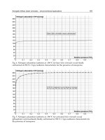
4.3 The efficiencies of the frame slotted ALOHA protocol and analysis
Fig. 6 shows the efficiency of the frame slotted ALOHA protocols with different frame
length in resolving the collision caused by different amount of RFID tags. For the
convenience of comparison, the protocol with frame length s is performed 256/s frames, for
example, the collison resolution protocol with frame size 16 is performed 16 frames. The
efficiency is defined as the identification ratio of RFID tags in these frames, calculated with
the number of RFID tags actually identified divided by the actual number of RFID tags.
From Fig. 6, it can be observed that as the population of RFID tags increase, the efficiency of
frame slotted ALOHA protocol decreases rapidly.
Fig. 6. The Efficiencies of Frame Slotted ALOHA Protocols with Different Frame Length
According to the calculation and simulation, the optimal frame length which the frame
slotted ALOHA protocol should adopt in resolving the collision caused by different number
of RFID tags is shown in Table 2.
RFID Tag
Population
1-14 15-30 31-61 62-124 124~
Optimal
Frame
Length
16 32 64 128 256
Table 2. Optimal Frame Length for the Identification of Different Number of RFID tags.
Radio Frequency Identification Fundamentals and Applications, Bringing Research to Practice
100
4.4 Simulation and analysis of the identification process
Fig. 7 shows the amount of frames needed in resolving the collision caused by different
amount of RFID tags using the frame slotted ALOHA based protocols with different frame
length. It can been seen that as the RFID tag population increases, the amount of frames
needed by these protocol will increase rapidly in exponential order.
Fig. 7. Amount of Frames Needed for the Frame Slotted ALOHA Protocol with Different
Frame Length
5. Conclusion
RFID holds the promise to enable human being to monitor the physical world with much
fine granularity and bridge the huge gap between the physical item world with the virtual
digital space. However, the collision occurred during the identification of multiple RFID
tags prevents this promise to become a reality.
In this chapter, the frame slotted ALOHA based RFID tag collision resolution protocols are
investigated, the stochastical distrubution model based on the binomial distrubution and the
honomgenous Markov chain for the collision resolution process are proposed, the
transisition matrix for the Markov chain is estabilished, vairous methods proposed for the
estimation of RFID tag population within the vicinity of the RFID reader are examined and
evalutaed. Some key factors that affect the performance of the protocols are evaluated and
examined. Numeirc simulations are performed to verify the research presented in this
chapter.
Stochastical Model and Performance Analysis of Frequency Radio Identification
101
6. Acknowledgement
The research work presented in this chapter is partially supported by the Natural Science
Fund of China (NSFC) under Grant No. 50625516, the National Fundamental Research
Program of China (973) under Grant No. 2009CB724204, and the High Talent Starting
Research Project of North China University of Water Conservancy and Electric Power under
Grant No. 200923.
7. References
Abramson, N. (1970). The ALOHA system - another alternative for computer
communications. in Proceeding of the 37th American Federation of Information
Processing Societies Computer Conference: 281-285.
Bonuccelli, M. A., Lonetti, F., & Martelli. F. (2007). "Instant collision resolution for tag
identification in RFID networks." Ad Hoc Networks 5(8): 1220-1232.
Cha, J. R., & Kim, J. H. (2006). Dynamic framed slotted ALOHA algorithms using fast tag
estimation method for RFID system. in Proceeding of the 3rd IEEE Conference on
Consumer Communications and Networking: 768-772.
Cha, J. R., & Kim, J. H. (2005). Novel anti-collision algorithms for fast object identification in
RFID system. in Proceeding of the 11th International Conference onParallel and
Distributed Systems: 63-67.
Engels, D. W., Foley. J. , Waldrop, J., Sarma, S., Brock, D. (2001). The networked physical
world: an automated identication architecture. In Proceedings of the Second IEEE
Workshop on Internet Applications.: 76-77.
Feller, W. (1970). An introduction to probability theory and its applications, Wiley
Press.
Finkenzeller, F. (2003). RFID Handbook: Fundamentals and Applications in Contactless
Smart Cards and Identification, John Wiley & Sons.
Kaplan, M. A. G., E. (1985). "Analytic Properties of Multiple-Access Trees." IEEE
Transactions on Information Theory IT-31(2): 255- 263.
Kodialam, P. M., & Nandagopal, P. T. (2006). Fast and reliable estimation schemes in RFID
systems. in Proceedings of the 12th annual international conference on Mobile
computing and networking: 322-333.
Leong, K. S., Ng, M. L., Grasso, A. R.,& Cole, P. H. (2006). Synchronization of RFID Readers
for Dense RFID Reader Environments. in Proceeding of the International
Symposium on Applications and the Internet Workshops: 48-51.
Roberts, L. G. (1975). "ALOHA packet system with and without slots and capture." ACM
SIGCOMM Computer Communication Review 5(2): 28-42.
Shih, D. H., Sun, P. L., Yen, D. C. & Huang, S. M. (2006). "Taxonomy and Survey of RFID
Anti-collision Protocols." Computer Communications 29(1): 2150-2156.
Stanford, V. (2003). "Pervasive Computing Goes the Last Hundred Feet with RFID Systems."
Pervasive Computing 2(2): 9-14.
Theodore, S. R. (2006). Wireless Communications: Principles and Practice, Addison
Wesley/Pearson Publisher.
Radio Frequency Identification Fundamentals and Applications, Bringing Research to Practice
102
Vogt, H. (2002). Efficient Object Identification with Passive RFID Tags. in Proceeding of the
International Conference on Pervasive Computing: 98-113.
Vogt, H. (2002). Multiple Object Identification with Passive RFID Tags. in Proceedings
of IEEE International Conference on Systems, Man and Cybernetics:
1854-1858.
Waldrop, J., Engels, D., & Sarma, S. (2003). Colorwave: an Anti-collision Algorithm for the
Reader Collision Problem. In Proceeding of the IEEE Wireless Communications
and Networking Conference: 1206-1210.
Wu, N. C., Nystrom, M. A., Lin, T. R., & Yu, H. C. (2006). "Challenges to global RFID
adoption." Technovation 26(12): 1317-1323.
Zhen, B., & Kobayashi, M., & Sgunuzy, M. (2005). "Frame ALOHA for Multiple RFID
Objects Identification." IEICE Transactions on Communications 88(3): 991-999.
7
Anti-collision Algorithms for Multi-Tag RFID
GENG Shu-qin, WU Wu-chen, HOU Li-gang and ZHANG Wang
VLSI and System Lab, Beijing University of Technology, Beijing 100022,
P. R. China
1. Introduction
RFID is one of automatic technology to identify and collect object data quickly through RF
digital signals. RFID increases productivity and convenience. RFID is used for hundreds, if
not thousands, of applications such as preventing theft of automobiles and merchandise;
gaining entrance to buildings; automating parking. But one of the largest disadvantages in
RFID system is its low tag (transponder) identification efficiency by tag collision.
Collisions are divided into interrogator collisions and tag collisions. Interrogator collisions
occur when neighbouring interrogators interrogate a tag simultaneously. Tag collision is the
event that the interrogator (reader) cannot identify the data of tag when more than one tag
occupies the same communication channel simultaneously. The reason is that whenever two
or more users are transmitting on the shared channel simultaneously, a collision occurs and
the data cannot be received correctly. This being the case, packets may have to be
transmitted and retransmitted until eventually they are correctly received.
As the most RFID systems use passive tags, frame sizes are limited in the framed slotted
ALOHA algorithm. Especially, since low-functional passive tags can neither detect collisions
nor figure out neighboring tags, a tag collision gives rise to the need for a tag anti-collision
protocol that enables the recognition of tags with few collisions and also executes in real-
time. Active RFID tags contain an on-board battery. They can communicate with
interrogator in far distance. Active tags can provide anti-collision by using various
combinations of some methods including time scope and frequency scope. When the
number of tags is large, for the conventional RFID anti-collision algorithm, the number of
slots required to read the tags increases exponentially as the number of tags does. Some
methods can solve this problem with complex algorithm consuming long communication
time.
Based on the analysis above, a good tag collision arbitration protocol for RFID tags should
have the following characteristics: First, a interrogator ought to identify all the tags inside its
own reading range. Since the interrogator cannot estimate the number of tags precisely, the
guarantee of recognizing all tags must be taken into consideration in the design of the tag
hard system and anti-collision protocol. Second, a tag should be identified while consuming
a small amount of resource, since the tag has low power. Thus, the tag anti-collision protocol
must load the tag with the least possible communication time.
This paper presents an improved dynamic framed slotted aloha algorithm (IDFSA) that may
solve this problem by dividing frequency of tags that is grouping the tags in different
Radio Frequency Identification Fundamentals and Applications, Bringing Research to Practice
104
frequency channel, reducing the number of slots and saving the communication time of
grouping with estimation. The interrogator requests every frequency in turn to check the
tags. In every frequency channel, the optimal frame size was set to enhance the system
efficiency. This Algorithm has been used in the 433MHz RFID system. The system
identification efficiency shows good performance.
2. Overview of several RFID anti-collision algorithms
In general, tag anti-collision protocols can be grouped into two broad categories: aloha-
based protocols and tree-based protocols. The former is composed of such as aloha, slotted
aloha, and frame slotted aloha that reduce the occurrence probability of tag collisions since
tags transmit at distinct times. The later is composed of such as the binary tree protocol and
the query tree protocol
,
based on the collision resolution algorithm studied in.
2.1 Tree-based RFID protocols
Fig. 1. An example of binary tree algorithm.
In tree-based RFID protocols, many protocols use binary tree algorithm. In this protocol, if a
collision occurs in a timeslot, the colliding tags are randomly separated into two subgroups
by independently selecting 0 or 1, until all tags are identified. The tags that select 0 transmit
their IDs to a interrogator right away. If a collision occurs again, the collided tags are split
again by selecting 0 or 1. The tags that select 1 wait until all the tags that select 0 are
successfully identified by the interrogator. And if all the tags that select 0 are resolved, the
tags that select 1 send their IDs to the interrogator. This procedure is repeated until there is
no further collision.
An example presented in figure1 illustrates the process of the anti-collision scheme adopting
the binary tree protocol. In the first timeslot, all tags select 0 or 1 randomly due to the
collision. And tag 1 and 3 select 0. Both tags send their IDs at the next timeslot and are
collided again. Tag1and 3 randomly select 1, no one select 0, then at the following timeslot,
Anti-collision Algorithms for Multi-Tag RFID
105
it is empty. At the fourth timeslot, it is collided again. Tag1 transmits its ID at the fifth
timeslot successfully by selecting 0, and the interrogator can then read the tag 3 because of
no collision at the next timeslot. After the collision resolution of tag 1 and 3, tag2, 4 and 5 are
collided at the seventh timeslot. Next, tag 4 selects 0 and tag 2and 5 select 1. Tag4 sends its
ID at the eighth timeslot. Thus tag 2 and 5 send at the twelfth and thirteenth timeslot,
respectively. Due to the no further collision, an interrogator finishes an identification
process.
Figure 2 shows the procedure of query tree searching algorithm. At t0, the interrogator
starts the anti-collision sequences by sending broadcast frame. Then at t1, the interrogator
sends ‘0’ to receive a tag’s UID of the first bit equal to ‘0’. At stage t2, the interrogator sends
‘00’ which is an accumulated UID stream that it is searching. By sending this accumulated
UID stream, the tags are free for counting the stage information. Moreover, the only
operations at tags are comparator or exclusive-OR operation. At stage t3, the interrogator
receives ‘00XX’ where ‘X’ means a collision. It sends ‘000’ firstly, and then receives the first
complete tag information ‘0000’. Again the reader sends ‘001’ which results an identification
if UID ‘0010’. This algorithm takes 8 stages to get the whole 4 UID stream. The de-activation
frame transmission is omitted for the simplicity.
Interrogator
t1 t2 t3 t4 t5 t6 t7
Broad
cast
0 00 000 001 01 1
Tag1 0000
Tag2 0010
Tag3 0101
Tag4 1100
Iterrogator receive xxxx 0xxx 00xx 0000 0010 0101 1100
Fig. 2. Sequences of the query tree searching scheme.
When the number of tag is small, tree-based protocols exhibit a reasonable performance. If
the number of tags is large, at the early stage, they may experience poor performance
because they might waste timeslots due to many collision slots until all tags are identified.
2.2 Basic framed slotted Aloha algorithm
BFSA algorithms use a fixed frame size and do not change the frame size until the process of
tag identification is over. When an RFID interrogator attempts to read tags, the interrogator
offers necessary information to the tags, such as the frame size and the random numbers.
Receiving this information, tags transmit their IDs at the computed timeslots in the frame. If
a timeslot has collision, the tags retransmit in the next read frame.
Figure 3 presents a process where tags are identified by BFSA. We assume that the frame
size and the number of tags are 4 and 5, respectively. Firstly, Tag 4 transmits its ID at
timeslot 1 of the frame 1. It is successfully identified. At the following timeslot, since a
collision occurs, the interrogator can not read the tags correctly. Neither tag 3 nor tag 5 is
identified by the interrogator due to the same reason. Thus, in the next frame, tag 1, 2, 3 and
5 must repeat the procedure until all tags are identified.
Radio Frequency Identification Fundamentals and Applications, Bringing Research to Practice
106
Frame1 Frame2
T1
Slot1 Slot2 Slot3 Slot4
T1
Slot1 Slot2 Slot3 Slot4
Que.
single Colli. Em. Colli. Que. single Colli. single Em.
Tag1
Tag2
Tag3
Tag4
Tag5
Fig. 3. Basic framed slotted Aloha algorithm
Because of the fixed frame size of BFSA, implementation is rather easy. If there are too many
tags, most of timeslots experience collisions, and none of tags may be identified during long
time. And many timeslots may be wasted by idle slots if the number of timeslots in the
frame is much larger than that of tags. Thus, it exhibits low performance of tag
identification.
2.3 Dynamic framed slotted Aloha algorithms (DFSA)
Time Separation based anti-collision uses two or more different ID tags in which different
tags have reply signals that occur in differing time positions. There are several methods of
changing the frame size. One of the popular dynamic framed slotted ALOHA algorithm
(DFSA) is that the interrogator regulates the number of slots of next frame using the last
frame slots with collision, the number of the empty slots, and the slots filled with one tag.
In an RFID system, the interrogator can dominate the multiple-access procedure, including
initiating communication, controlling read process, and receiving responses from tags. In a
dynamic frame length ALOHA anti-collision algorithm, the interrogator initiates a read
cycle by broadcasting a request command to all tags under its coverage. This request
command also includes a dynamic parameter, called the frame length, by which each tag
randomly selects one of the available time slots and transmits its ID at the selected time slot.
For a given time slot, there are only three possible outcomes: idle, successful transmission
(the slots filled with one tag), and collision. The channel is idle if no tag transmits its ID in
the time slot. A successful transmission means one tag only sends it’s ID. If two or more tags
transmit in the same time slot, the interrogator suffers from collision and no tag can be read.
After a read cycle, the interrogator can observe empty slots, singly occupied (or successful)
slots, and collision slots. If the number of collision slots is greater than zero, the interrogator
needs to estimate the number of tags that are present at the beginning of the read cycle
according to the triple parameter and then to forecast the number of unread tags. According
to the number of unread tags, the interrogator then determines an appropriate frame length
for the next read cycle. When the number of slots with collision is over the upper threshold,
the interrogator increases the number of slots. If the collision probability is smaller than the
lower threshold, the interrogator decreases the number of slots. The read process stops
when there is no collision in the read cycle. In the presence of a large amount of collision
slots, it is reasonable to assume that the number of tags is great. In this case, the number of
empty slots should be very small. In contrast, a large amount of empty slots means that just
a few tags are present.
Anti-collision Algorithms for Multi-Tag RFID
107
Fig. 4. Slots of Dynamic Framed Slotted ALOHA
DFSA algorithm can enhance channel usage efficiency and identify the tag efficiently
because the interrogator regulates the number of slots according to the number of tags (see
figure4). When the number of tags is small, DFSA algorithm can identify tags efficiently.
However the maximum frame size for a concrete system is definite. When there are a
number of tags, changing the frame size alone must be limited to the maximum frame size.
So it is not fit for large tags system.
2.4 Enhanced dynamic framed slotted Aloha (EDFSA) algorithm
Collision efficiency is a function of the number of communicating tags presented within the
interrogator communication range.
According Chebyshev’s inequality, the outcome of a random experiment involving a
random variable X is most likely somewhere near the expected value of X. Thus estimation
function (1) measures the difference between the real results and the expected values to
estimate the number of tags for which difference becomes minimal.
,
0
0
,
01 1 1
,
(, , , )min
Nn
Nn
vd c
Nn
c
c
a
C
NC C C a C
C
a
ε
⎛⎞
⎛⎞
⎜⎟
⎜⎟
=−
⎜⎟
⎜⎟
⎜⎟
⎜⎟
⎝⎠
⎝⎠
(1)
The number of tags is estimated using both the number of slots N used in the read cycle and
the results of the previous read cycle as a triple of numbers
01
,,
c
CCC
<
> that quantify
respectively the empty slots, slots filled with one tag, and slots with collision as Equation
(1). In Equation (1),
,,,
01 2
,,
Nn Nn Nn
aaa
≥
<
> respectively denote the empty slots, slots filled with
one tag, and slots with collision where the number of slots is N and the number of tags is n.
Given N slots and n tags, the number 0, 1, r of tags in one slot is binomially distributed, and
the expectation value for them is given by the follow eqation
,
11
1
rnr
Nn
r
n
aN
r
NN
−
⎛⎞
⎛⎞⎛ ⎞
=−
⎜⎟
⎜⎟⎜ ⎟
⎝⎠⎝ ⎠
⎝⎠
(2)
When n is large, the optimal number of slots can be obtained by
1, 1Nn n
≈
+>> (3)
The above equation tells us that when the number of tags and the number of slots are
approximately the same, the system efficiency becomes the maximum. According this, if the
number of unread tags is sufficiently large, the tags can be grouped and allowing only one
group to respond. The number of groups can be obtained by Modulo operation.
M
unread tags N=
(4)
Radio Frequency Identification Fundamentals and Applications, Bringing Research to Practice
108
In a word, when the number of unread tags is large, EDFSA divides the tags into groups
with estimation. However, in practical system, when EDFSA based estimation grouping the
number of unread tags is used, the time of interrogator command is long that can prolong
the time of communication, which will influence the number of slots in a frame. So a simple
easily realized method that improved dynamic framed slotted aloha algorithm (IDFSA) is
presented as follows.
3. Improved dynamic framed slotted ALOHA (IDFSA) algorithm
This system experiment is based upon the assumptions that (a) Lots of tags are presented in
the interrogator’s field at the same time, the number of tags being present is not known in
advance. The number of tags for every test is not known in advance. (b) Capture effect is not
taken into consideration. (c) Experiment is trying to identify all tags presented in the field of
the interrogator.
3.1 The description of IDFSA
For a practical system, the maximum time of one tag communication can be known, and the
maximum number of slots in a frame can be calculated. The maximum total number of tags
can be known too. If the number of tags is large, from equation (3), when the frame size N is
equal to or close to the number of tags, the system efficiency becomes the maximum. In
practical system, many RF chips have many frequency channels (e.g. nRF905). The tags can
be divided into groups in different frequency channel to enhance the identification
efficiency and to save the time of the command of the EDFSA. Grouping the tags can be
accomplished in the system design period. Every group of tags has their own frequency.
The number of frequency channels can be gotten as follows
max
/
total
Gn N
=
(5)
Where n
total
is the number of system maximum total tags; N
max
is the number of system
maximum frame size. G is the number of frequency channels.
The maximum number of tags in every group is approximate to the maximum frame size. In
one frame, according to the number of identified tags, C
1
the number of slots given one tag
can be known. The collision C
c
can be known by the difference of number of address match
(AM) and data ready (DR). C
c
is divided by frame size N
i
, and then collision efficiency P
r
can be gotten. Next frame size N
i+1
can be known from (4). If 15%< C
c
/ N
i
<40 %, next frame
size N
i+1
does not change. If C
c
/N
i
<15%, next frame size N
i+1
is N
i/2
. If C
c
/N
i
>40%, next
frame size N
i+1
is 2N
i
. Until the interrogator identifies all tags in one channel, another
channel can start to check.
1,
/2, / 15%
15% / 40%
2 / 40%
ici
ii ci
ici
NCN
NN CN
NCN
+
⎧
<
⎪
⎪
=<<
⎨
⎪
>
⎪
⎩
(6)
The frequency channel group can be made in the system design period not in the
communication period, and the real-time estimation method is not used by the IDFSA. It not
only saves the time of grouping with estimation during the communication, but also
enhances the identification efficiency.
Anti-collision Algorithms for Multi-Tag RFID
109
3.2 Performance analysis of IDFSA algorithm
For example, this system has total 210 tags; the maximum number of a frame size is 64 (see
table 1). (3) is used in the condition that the number of tag is very large. According (3) the
number of frequency channels is 210/64≈3.
In this system, the frequency channels of tags are 433 MHz, 433.4 MHz and 433.9MHz. For
every frequency channel, the number of real time slots can be decided by IDFSA. The
interrogator requests every frequency by turns to check different frequency tags. This can
enhance the system efficiency.
n
total
N
max
G
channel
210 64 3
Table 1. The total system tags vs. maximum number of a frame size
Figure 5 is the system efficiency vs. groups and tags number. With the number of tag
increasing, it can be seen that system efficiency of 3groups is higher than that of 2 groups;
System efficiency of 2groups is higher than that of 1 groups.
In figure 4, it can be seen that the line groups 1, 2, 3 have two crossing point A, and B.
According this, n
A
and n
B
can be obtained by
,,/2
11
//
Nn Nn
aNa N= (7)
,/2 ,/3
11
//
Nn Nn
aNaN= (8)
When N is 64 slots, n
A
=88 and n
B
=155.
20 40 60 80 100 120 140 160 180 200
0.05
0.1
0.15
0.2
0.25
0.3
0.35
0.4
n tags
system efficiency
1 Frequency channel
2 Frequency channels
3 Frequency channels
A
B
N=64
Fig. 5. System efficiency vs. frequency channels
When N is 64 and 89≤n≤154, to achieve the optimal system efficiency, the number of
frequency channels can be 2. Similarly, when N is 64 and 155≤n≤218, to achieve the optimal
system efficiency, the number of frequency channels can be 3. The result can be seen in table
2.
Radio Frequency Identification Fundamentals and Applications, Bringing Research to Practice
110
N
total
G N/G P
r
… … … …
156~219 3 64 0.19516~0.31621
88~155 2 64 0.15061~0.34476
45~87 1 64 0.15606~0.40053
23~44 1 32 0.16073~0.40157
… … … …
Table 2. Tags、frequency channels、the number of slots and collision efficiency
Fig. 6. The collision of slots number is 2N
i
、N
i
、Ni/2
Figure6 is the collision efficiency of 2N
i
, N
i
and N
i/2
. When the collision efficiency is 15%,
the number of tags is near to the down threshold the same as the table 1. When the collision
efficiency is 40%, the number of tags is near to the upper threshold the same as the table 1.
System identification efficiency is between 34.94% ~37.085% in one frame once a time.
Figure 7 is the collision efficiency and identification efficiency. The collision efficiency of the
traditional method is between 30%-70%, and the system identification efficiency is the line
between EF in figure 3. The collision efficiency of IDFSA is between 15%-40%, and the
system efficiency is between 34.94% ~37.085% in one frame once a time. It is the line
between CD in figure 7. It can be seen that system identification is higher than the
traditional method.
4. Conclusion
It is an important problem to enhance the tag identification efficiency. When the number of
tags is large, for the conventional RFID anti-collision algorithm the number of slots required
to read the tags increases exponentially as the number of tags does. The proposed IDFSA
algorithm may solve this problem by grouping the tags in different frequency channel,
saving the time of grouping with estimation. In every frequency channel, DFSA is used to
Anti-collision Algorithms for Multi-Tag RFID
111
set the optimal frame size to enhance the identification efficiency. This Algorithm is used in
the 433MHz RFID system, tags anti-collision shows good performance.
Fig. 7. Collision efficiency and identification efficiency
5. References
Engels, D. & Sarma S. (2001). The Reader Collision Problem, Technical Report MIT-
AUTOID-WH007, Auto-ID Center, Nov. 2001.
Engels, D. et al, (2003). An Anticollision Algorithm for the Waldrop Reader Collision,
Proceedings of IEEE Int’l Conf. Comm., pp. 1206-1210, ISSN: 05361486, Anchorage,
AK, United states, May 2003, Institute of Electrical and Electronics Engineers Inc.,
NJ
Finkenzeller, K. (2003). RFID handbook - Second Edition, John wiley & sons, ISBN: 0470844027,
England
Haifeng, L. et al, (2006). A Modified Dynamic Binary Search Anti-collision Algorithm, IET
Conference Publications, pp. 78, ISBN-10: 0863416446, Hangzhou, China, Nov. 2006,
Institution of Engineering and Technology, SG1 2AY, United Kingdom.
Jae-Min, S. & Seong-Whan, K. (2006). Collision-Resilent Multi-state Query Tree Protocol for
Fast RFID Tag Identification, Conf. Rec. 2006 Int. Conf. Computational Intelligence and
Security, pp. 1159-1162. ISBN: 1-4244-0605-6, Guangzhou, Nov. 2006, Guangzhou
Junbong, E. & Tae-Jin, L. (2007). Framed-Slotted ALOHA with Estimation by Pilot Frame
and Identification by Binary Selection for RFID Anti-collision. 2007 International
Symposium on Communications and Information Technologies, pp. 1027-1031, ISBN-13:
978-1-4244-0976-1, Sydney,. NSW, Australia, Oct. 2007, Inst. of Elec. and Elec. Eng.
Computer Society, NJ 08855-1331
Landt, J. (2005). History of RFID. IEEE Potentials, Vol.24, No. 4, (Oct Nov. 2005) pp. 8 – 11,
ISSN: 0278-6648
Radio Frequency Identification Fundamentals and Applications, Bringing Research to Practice
112
MIT Auto-ID Center (2003). Draft protocol specification for a 900MHz Class 0 Radio
Frequency Identification Tag, http://www. epcglobalinc.org/, Feb., 2003. (binary
tree)
Myung, J. et al, (2006). Adaptive Binary Splitting for Efficient RFID Tag Anti-Collision. IEEE
Comm. Letters, vol. 10, no.3, (March 2006) page numbers (144-146), ISSN: 10897798
Myung, J. et al, (2006). Tag-splitting : Adaptive Collision Arbitration Protocols for RFID Tag
Identification. IEEE transactions on parallel and distributed systems, Vol. 18, NO.6,
(June 2007), page numbers (763-765), ISSN: 1045-9219Philips Semiconductors,
UCODE, iconductors. philips.com, 2005.
Sangho, S. & Sin-Chong, P. (2008). Efficient RFID Anti-collision scheme with multi-collision
reflected frame request. 2009 6th IEEE Consumer Communications and Networking
Conference, pp. 1-5, ISBN-13: 9781424423095, Las Vegas, NV, United states, 1,2008,
Inst. of Elec. and Elec. Eng. Computer Society, NJ 08855-1331, United States.
Sarma, S. et al, (2001). Radio Frequency Identification and the Electronic Product Code. IEEE
Micro, Vol. 21, No. 6, (November/December 2001) pp. 50-54, ISSN: 02721732
Sarma, S. et al, (2002). RFID Systems and Security and Privacy Implications, Proceedings of
Workshop Cryptographic Hardware in Embedded Systems, pp. 454-470, ISBN-10: 3 540
00409 2, Redwood Shores, CA, USA, Aug. 2002, Springer-Verlag, Berlin
Song-sen, Y. et al, (2007). RFID Anti-collision algorithm Based on Bi-directional Binary
Exponential Index. Proceedings of the IEEE International Conference on Automation and
Logistics, pp.2917-2921, Jinan, China, August 2007, Inst. of Elec. and Elec. Eng.
Computer Society, NJ 08855-1331
Su-Ryun L. et al, (2005). An Enhanced Dynamic Framed Slotted ALOHA Algorithm for
RFID Tag Identificatio, Proceedings of Second Annual International Conference on
Mobile and Ubiquitous Systems -Networking and Services, pp. 1-7, ISBN-10:
0769523757, San Diego, CA, United states, July 2005, Institute of Electrical and
Electronics Engineers Computer Society, Los Alamitos
Vogt, H. (2002). Efficient Object Identification with Passive RFID Tags, Proceedings of Int’l
Conf. Pervasive Computing, pp. 98-113, ISSN : 15308669, Zurich, Switzerland, Apr.
2002, John wiley and sons Ltd, 2002, Berlin
Vogt.,H. (2002). Multiple Object Identification with Passive RFID Tags. 2002 IEEE
International Conference on Systems, PP. 651-656, ISSN: 08843627, Yasmine
Hammamet, Tunisia, October 2002, Institute of Electrical and Electronics Engineers
Inc., NJ
Weis, S. et al, (2003). Security and Privacy Aspects of Low-Cost Radio Frequency
Identification Systems, Proceedings of First Ann. Conf. Security in Pervasive
Computing, pp. 201-212, Boppard, Germany, Mar. 2003, Springer-Verlag, Berlin
Zhai,J. & Wang, G. (2005). An Anti-Collision Algorithm Using Two-Functioned Estimation
for RFID Tags, Proceedings of Int’l Conf. Computational Science and Its Applications, pp.
702-711, Singapore, May 2005, Springer-Verlag, Berlin