Radio Frequency Identification Fundamentals and Applications, Bringing Research to Practice Part 10 potx
Bạn đang xem bản rút gọn của tài liệu. Xem và tải ngay bản đầy đủ của tài liệu tại đây (918.81 KB, 20 trang )
Evaluation of Group Management of RFID Passwords for Privacy Protection
173
b. The system must use as little item information as possible for the identifier of RFID tags
to protect possession privacy.
c. The system must avoid using unique IDs for the identifier of RFID tags, as much as
possible, to protect location privacy.
RFID
interrogator
RFID
interrogator
RFID tag 1
RFID tag 1
password X
RFID tag 2
RFID tag 2
password X
RFID tag 3
RFID tag 3
password X
password X
(a) Common RFID Password
RFID tag group1
RFID tag group1
password A
RFID tag group2
RFID tag group2
password B
RFID tag group3
RFID tag group3
password C
RFID
interrogator
RFID
interrogator
Password
generator
password A
password B
password C
(b) Group RFID Password
Fig. 1. Systems in which interrogators access RFID tags by using RFID passwords
3. An RFID system that generates group RFID passwords
3.1 Group RFID password generation method
An RFID system that generates group RFID passwords only allows authorized interrogators
to access RFID tags, and allows those interrogators to read or write data in the RFID
memory. Each RFID tag receives an RFID password from an interrogator and authenticates
the interrogator; i.e., judges whether the interrogator is authorized for access.
This system sets data called “PASS KEY” for generating a different RFID password for every
group of tags, and sets the RFID password as an RFID tag. A group RFID password
generation algorithm that finds the right RFID password for each group of RFID tags and
sends it to the RFID tag is mounted in an authorized interrogator. The parameters of the
grouping RFID password generation algorithm are a master key and a PASS KEY written in
an RFID tag.
Figure 2 is a flow chart of the procedure for generating and managing the group RFID
passwords.
In the preparation stage, a user chooses a random number as the PASS KEY. The group
RFID password generation algorithm calculates this PASS KEY by using a function with
collision resistance and pre-image resistance; i.e., a hash function with a master key. The
calculation result that this algorithm outputs is used as the group RFID password. The
system sends and sets selected PASS KEYs and the generated group RFID passwords to
Radio Frequency Identification Fundamentals and Applications, Bringing Research to Practice
174
RFID tags. Since a different PASS KEY is chosen for each group of RFID tags, the RFID
password is also set as a different value for each group of RFID tags.
Preparation stage
RFID interrogator
RFID interrogator
RFID tag
RFID tag
PASS KEY password
check
Hash
function
master
key
PASS KEY
password
Hash
function
master
key
PASS KEY
password’
PASS KEY
Random number
generator
Authentication OK
DATA
Read
Write
Read
Write
Fig. 2. Procedure for generating group RFID passwords
Whenever a user accesses an RFID tag, the user’s interrogator first demands the RFID PASS
KEY. The RFID tag receives this demand and reports the PASS KEY to the interrogator. The
interrogator first calculates the PASS KEY that it receives from the RFID tag by using a
master key and a hash function, and then generates a group RFID password. The
interrogator then sends the generated group RFID password to the RFID tag. The RFID tag
compares the received group RFID password to the group RFID password that was
programmed into it in the preparation stage. If the two RFID passwords are the same, the
RFID tag will change to the secured state. When the RFID tag changes to the secured state,
the user can read or write to the data in the RFID memory.
Authorized users are not the only ones who can get the PASS KEY from this RFID tag;
unauthorized people or agents can also get it. However, since those without authorization
do not know the master key, they cannot generate the group RFID password from the PASS
KEY, and they cannot read or write to data in the RFID tag.
Generating group RFID passwords requires that the procedure to generate two RFID
passwords with the same value from two different PASS KEYs must be made difficult, and
decoding a master key from a RFID password and a PASS KEY must also be difficult.
Therefore, we adopt a hash function equipped with collision resistance and pre-image
resistance as our group RFID password generation algorithm. To construct an RFID system
with higher security, an effective method is to use a hash function that has been previously
evaluated by the public, such as SHA-1, and to store the master key in a tamper-resistant
device.
Evaluation of Group Management of RFID Passwords for Privacy Protection
175
3.2 Structure of an RFID system with a group RFID password generation method
Here, we provide an example of the structure of an RFID system that uses a group RFID
password generation method that sets up and manages group RFID passwords in RFID
tags. Figure 3 presents the structure of this system. This system uses RFID tags conforming
to the Secure RFID Project specification based on ISO/IEC 18000-6 Type C. The tags are
mounted with rewritable memory and an authentication function. The system also includes
interrogators, conforming to the Secure RFID Project specification, that communicate with
the RFID tags and a tamper-resistant device that restricts users and generates group RFID
passwords. The system has middleware that controls the interrogators, the tamper-resistant
device, and an RFID application. The middleware and the application can be installed in a
terminal. The tamper-resistant device has a user authentication function to prevent
unauthorized use of this system and a grouping RFID password generation algorithm that
minimizes the damage when RFID passwords are disclosed to unauthorized users.
The user authentication function in the tamper-resistant device applies PIN authentication
technology. Users can only use an interrogator after they input an authentic PIN. If they fail
to do so, they cannot use an interrogator and cannot access RFID tags. This PIN
authentication function can prevent unauthorized use of the interrogator, even if the
interrogator is stolen.
The group RFID password generation algorithm is also mounted in the tamper-resistant
device, and is processed within this device to prevent leaks and misappropriation of the
group RFID password generation algorithm.
Authentication
RFID middleware
RFID Tag
RFID Tag
RFID interrogator
RFID interrogator
Tamper resistant
device
Tamper resistant
device
Password
generator
PASS KEY,
password
unique ID
Password
checker
master key
RFID
application
RFID
application
PASS KEY password
Request ID
User
authenticator
ID
(1)
(2)
(3)
Fig. 3. Structure of system for group RFID password generation
Radio Frequency Identification Fundamentals and Applications, Bringing Research to Practice
176
4. Solutions to privacy problems
To protect possession privacy, PASS KEY data should not include any data that identifies
items; e.g., an item code or a product number. PASS KEY data should be meaningless data
such as a random number. If the PASS KEY is unique and anyone can read it, location
privacy is at risk. Moreover, if the PASS KEY of many RFID tags is set up to be identical,
many tags will be affected if one RFID password is leaked since the RFID password for
every group of RFID tags is also identical. Therefore, some PASS KEYs should be set up as
identical to reduce the risk of privacy invasion, and some PASS KEYs must be distributed so
that the effects of RFID password disclosure will be limited. We estimated the number of
equivalent PASS KEYs that satisfies these two demands by the following methods.
When a PASS KEY is read, the probability of those who are carrying the RFID tag to be
specified by that PASS KEY can be calculated as the number of those who can be found out
of the entire group carrying an RFID tag that stores identical PASS KEYs. We call this
probability the specific probability R.
When we define the number of the tags with the same PASS KEY as the equivalent number
M, the specific probability of privacy invasion R can be explained as a reciprocal of the
equivalent number M.
MR 1
=
(1)
On the other hand, the influence level of RFID password disclosure, E, when an RFID
password is leaked is calculated as the number N of the RFID tags in the market and the
equivalent number M, which is the number of tags with the same RFID password.
NME
=
(2)
Risk, F, is defined as the sum of the weight of the specific probability R and the influence
level E. To improve the balance of both specific probability R and the influence level E, we
calculate the equivalent number M that provides the lowest risk F. Here, the weight is
expressed as w.
NMwMwERF +=+= 1
(3)
NwM
1
min
−
= (4)
The weight w corresponds to the probability that an RFID password will be leaked.
Figure 4 shows the relations between the probability of privacy invasion R, the influence level
of RFID password disclosure E and the risk F. In this figure, we show that if specific
probability R is set too low, the risk F become high because the influence level E becomes high.
In the following section, we find the effective equivalent number M
min
in the case of a
shopping mall where RFID tags are used.
5. Evaluation of the proposal method’s applicability
5.1 Trail analyzing simulation for invasion of location privacy
In this section, we simulate the probability of someone being able to invade a consumer's
location privacy in a shopping mall. We assume that consumers carrying items with RFID
tags move about in a shopping mall, and unauthorized people or agents secretly install
Evaluation of Group Management of RFID Passwords for Privacy Protection
177
Equivalent number M
Risk F
Specific probability R
Influence level E
Risk F
M
mi n
=(w
-1
N)
1/2
R=1/M
wE=wM/N
F=R+wE
Fig. 4. Balance of both specific probability R and the influence level E
interrogators and trail consumers by reading the RFID tags. We measure the traceable
distance for some equivalent number M, and find the equivalent number M
min
at which the
traceable distance becomes the shortest in the case of a shopping mall.
a. Modelling the shopping mall
We assume four models about the shape of a shopping mall as shown in Table 1 and Fig. 5.
The floor space of all models is 40,000 m
2
. There is an entrance in the centre of each
neighbourhood of the first floor of the shopping mall. In each model, the shopping mall
contains 100 stores. Each store’s floor space is 225 m
2
and one interrogator is installed in
each store. The width of all passages in each model is 10 m. Each shopping mall always
contains 2,000 consumers. A PASS KEY value of an RFID is recorded along with the position
and the time when a consumer comes within the readable range of an interrogator, which is
2 m. Model 1 is a 200 x 200 m square within which consumers can move freely because there
are no walls dividing stores. Model 2 is a 200 x 200 m square within which consumers move
through passages because there are walls separating the stores. Model 3 is a frame type
building, around a central courtyard, with a 1,160 m outside perimeter and an 840 m inside
perimeter; there is a single passage with stores on both sides. Model 4 is a building with four
50 x 50 m floors where consumers move between floors using a central escalator or one of
four elevators.
Model # Space Floors Walls Entrances Interrogators Visitors
1 40,000 m
2
1 No 4 sides of 1F 100 2,000
2 40,000 m
2
1 Set 4 sides of 1F 100 2,000
3 40,000 m
2
1 Set 4 sides of 1F 100 2,000
4 40,000 m
2
4 Set 4 sides of 1F 100 2,000
Table 1. Model parameters
Radio Frequency Identification Fundamentals and Applications, Bringing Research to Practice
178
GOAL
GOAL
ST ART
START
GOAL
GOAL
ST ART
START
GOAL
GOAL
ST ART
START
GOAL
GOAL
ST ART
START
GOAL
GOAL
STA RT
ST ART
GOAL
GOAL
STA RT
ST ART
ST ART
START
ST ART
START
GOAL
GOA L
GOAL
GOA L
Model 1 Model 2 Model 3
Model 4
1F 2F 3F 4F
Fig. 5. Types of shopping mall
The consumer movement pattern in this simulation is as follows:
• Each consumer's starting point is randomly chosen from among four entrances.
• The stores to which each consumer goes are chosen at random.
• The number of stores to which each consumer goes varies randomly from 3 to 7.
• A consumer begins by moving to the nearest selected store from the chosen starting
point.
• If a consumer arrives at a store, he will stay once and then will move to the nearest
selected store from there.
• If a consumer arrives at the last selected store, he will then return to the starting point.
• The time a consumer spends at a store varies randomly from 10 minutes to 30 minutes.
• The distance which a consumer moves in each step is 5 m.
• The speed at which a consumer moves is 1 m/s.
b. Trail analyzing system
This system collects and analyzes log data on the detection of RFID tags with the installed
interrogators for consumer trail analysis. The log data consists of an interrogator's ID, the
installation position of the interrogator (x, y), a step number, and a PASS KEY value of an
RFID. This system creates a consumer's trail by extracting arbitrary PASS KEY values in
connection with the consumer out of log data, and sorting these data by time. In this system,
there may be some RFID tags with the same PASS KEY values. To trail a consumer as fully
as possible, the system disregards data detected at any point at which a consumer cannot
physically arrive.
5.2 Result of the trail analyzing simulation
Figure 6 shows a simulation result for the case of five consumers who possess RFID tags
with the same PASS KEY value in model 1. This figure shows the route consumer An
actually followed and the route for the same consumer observed by the trail analysis system.
The routes of the other consumers are also shown. Each white circle indicates an
interrogator. In this case, consumer A started from point (110, 10). After moving 135 m, he
encountered consumer C at point (90, 130). Therefore, the traceable distance was 135 m since
Evaluation of Group Management of RFID Passwords for Privacy Protection
179
it became impossible for the trail analyzing system to distinguish consumer A and consumer
B after their routes met.
0
50
100
150
200
0 50 100 150 200
observed route of A
real route of A
observed route of others
real route of others
interrogator
E
D
B
C
A
Fig. 6. Flow line analysis simulation result
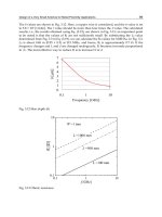
Figure 7 shows histograms of the traceable distance L acquired through 10,000 simulations
when the equivalent number M of PASS KEY was 1, 5, 10 or 20 and the shopping mall type
was Model 1. The respective standard deviation was 148, 104, 55, and 27. This figure shows
the traceable distance L becomes short if the equivalent number M increases.
Figure 8 shows the average of the traceable distance L as a function of the equivalent
number M in each of the four models. When the equivalent number M was 1, the traceable
distance L was 817 m; when the equivalent number M was 70, the traceable distance L was
0.9 m. In this simulation there were many consumers possessing RFID tags with the same
PASS KEY value, so we know there was a high probability that consumers possessing RFID
tags with the same PASS KEY value would meet and these consumers would consequently
be hard to trail.
Next, we consider the effect of RFID password disclosure E in this simulation. The influence
rate wE when an RFID password is leaked is expressed as follows from equation (2). The
probability w of an RFID password being decoded by brute force attack in one year and
subsequently leaked is set to 50%. The number N of the RFID tags in the shopping mall is set
to 2,000.
MwE
2000
5.0
=
(5)
The risk F obtained from this simulation result and equation (5) is shown in Fig. 8. (The right
vertical axis in the figure shows the rate of risk F). This figure shows that an equivalent
number M of about 45 leads to the smallest risk F. When the equivalent number M is 45, the
influence level of RFID password disclosure E is about 2% and the traceable distance L is
about 3.5 m although the distance which a consumer walked in a shopping mall is 817 m.
Radio Frequency Identification Fundamentals and Applications, Bringing Research to Practice
180
0
100
200
300
400
500
600
0
100
2
0
0
3
0
0
4
0
0
5
0
0
60
0
70
0
80
0
900
1000
1100
1200
1
3
00
1
4
00
Traceable dis ta n c e L (m )
Frequency
M=1
0
500
1000
1500
2000
2500
3000
0 100 200 300 400 500 600 700
T raceable distance L (m )
Frequency
M=5
0
1000
2000
3000
4000
5000
0 100 200 300 400 500 600 700
Traceable distance L (m )
Frequency
M =10
0
2000
4000
6000
8000
0 100 200 300 400 500 600 700
Traceable distance L (m )
Frequency
M =20
Fig. 7. Traceable distance L in case M = 1, 5, 10 and 20
Evaluation of Group Management of RFID Passwords for Privacy Protection
181
0.1
1
10
100
1000
0 102030405060708090100
Equivalent num ber M
Traceable distance L (m)
0.01
0.1
1
10
100
R is k (% )
Model 1
Model 2
Model 3
Model 4
Influence level wE
Risk F
Fig. 8. Traceable distance L vs. the equivalent number M
6. Conclusion
RFID privacy problems will have to be solved before items with RFID tags can be safely
provided to consumers on a large scale. Here, we considered the location privacy problem
of unauthorized persons or agents being able to trail a person by tracing a unique ID
recorded in an attached RFID tag.
We proposed a method for using RFID tags that include an interrogator with an algorithm
to generate RFID passwords. This method groups RFID passwords for RFID tags in a way
that protects consumer privacy.
We simulated the possibility of trailing a consumer in a shopping mall. We investigated
how much the traceability of a consumer changed when the proposed method was applied.
Simulation results showed that the traceability fell by about 0.4% when the influence level of
RFID password leakage was 2% in this model.
In practice, it may be difficult to read a consumer’s RFID tag from distances like those
assumed in this simulation because RFID is easily influenced by various environmental
conditions. However, even if invasion of privacy is technically difficult, consumers will
remain concerned as long as there is any possibility of invasion of privacy through RFID.
Therefore, our proposed method will be useful for RFID system application.
Radio Frequency Identification Fundamentals and Applications, Bringing Research to Practice
182
7. Acknowledgment
This paper is based on the achievement of a Japanese National Research and development
project, the Secure RFID Project that was conducted by METI (Ministry of Economy, Trade,
and Industry) for the eight months from August 2006 to March 2007.
8. References
CASPIAN; ACLU; EFF & EPIC (2003). "Position Statement on the Use of RFID on Consumer
Products,"
Albrecht, K. & Mcintyre, L. (2005). "Spychips: How Government And Major Corporations Are
Tracking Your Every Move," Thomas Nelson Inc., 1595550208, Tennessee, USA.
GS1 EPCgloval. (2005). "Guidelines on EPC for Consumer Products,"
Weis, S. (2003). "Security and Privacy in Radio-Frequency Identification Devices," Masters
Thesis, Massachusetts Institute of Technology, Massachusetts, USA.
Juels, A. & Pappu, R. (2003). "Squealing Euros: Privacy-Protection in RFID-Enabled
Banknotes," Proceedings of Financial Cryptography '03, pp.103-121, Guadeloupe,
France.
Engberg, S.J.; Harning, M.B. & Jensen, C.D. (2004) "Zero-Knowledge Device Authentication:
Privacy and Security Enhanced RFID Preserving Business Value and Consumer
Convenience," Proceedings of the Second Annual Conference on Privacy, Security and
Trust (PST'04), pp.89-101, New Brunswick, Canada.
Satoh, A. & Inoue, T. (2007). "ASIC-Hardware-Focused Comparison for Hash Functions
MD5, RIPEMD-160, and SHS," the VLSI journal, Vol.40, pp.3-10, 0167-9260.
Honzawa, A. (2008). "Secure RFID Project, Spread Use for Product Cycle Management,"
Proceedings of GRIFS Workshop, Halifax, UK.
13
A Mobile RFID Authentication Scheme Based
on the COMP-128 Algorithm
Jia-Ning Luo
1
and Ming Hour Yang
2
1
Information and Telecommunication, Ming Chuan University
2
Information Computer Science, Chung Yuan Christian University
Taoyuan, Taiwan
1. Introduction
Radio frequency identification (RFID), based on the MIT Auto-ID project [1], is a technology
that uses wireless transmission to identify an object. RFID is seeing increased use in various
industries as an alternative to the bar code. An RFID system consists of three components:
the reader, the tag, and the back-end database. Some advantages of an RFID system are that
it does not require direct contact with the tag, and can scan multiple tags simultaneously.
However, because the reader uses wireless technology to communicate with the tag and the
EPC Class 1 Gen 2 protocol [2] does not have a well-designed access mechanism to protect
the tag data privacy and location privacy, a malicious attacker is able to retrieve the tag’s
information by listening to the traffic between the reader and the tag [3]. To protect the
information stored on a tag, Juels [5] and Weis [6] proposed methods for a tag to lock or
destroy itself when attacked. However, these methods are an inconvenience to normal users.
Many studies [7] propose authentication mechanisms in RFID systems, in which only
authorized readers can read the correct information storing on the tag. However, due to
hardware limitations, an RFID tag cannot perform complex operations, such as traditional
symmetric and asymmetric encryption algorithms.
Previous research proposes using the simple XOR operation to encrypt messages in RFID
authentication protocols. Some studies use the RFID tag’s built-in CRC function to achieve
message authentication [8]. Other studies [4][9][10][11] use the one-way hash function to
enhance authentication protocol security. This study briefly explains these authentication
mechanisms and analyzes existing security issues.
Karthikeyan [12] proposed a mutual authentication scheme that uses two matrices and the
corresponding anti-matrix. In this approach, the multiplication of a vector key and the
matrix serves as an authentication index for the tag. However, in Karthikeyan’s scheme, the
tag does not verify reader’s return value; that is, the attacker can re-send the message to
track tag’s location.
Duc [8] used the built-in CRC function of an RFID tag to generate a message authentication
code (MAC) consisting of a random number and a secret previously shared between the tag
and the reader. Duc uses the MAC to authenticate the tag and update the pre-shared secret.
However, Duc’s scheme cannot prevent the forge attack and it does not have forward
security. To enhance Karthikeyan and Duc’s scheme, Chien [13] proposed a synchronization
Radio Frequency Identification Fundamentals and Applications, Bringing Research to Practice
184
authentication protocol based on CRC. However, because CRC is a linear function, no
protocols based on CRC can resist the forge attack.
Other studies use a one-way hash function in the RFID authentication mechanism
[4][9][10][11][14]. Henrici proposed a hash based scheme [9] in which the tag sends h(ID)
instead of its unique ID to the reader. Henrici’s scheme protects the tag’s location privacy
because the attacker cannot derive the tag’s ID from h(ID).
In Henrici’s scheme, if the message between reader and tag is lost, the tag will be out-of-
sync. To improve Henrici’s scheme, Yang proposed a novel mutual authentication
mechanism [10] that uses index-pseudonyms and XOR method. In this case, the tag
generates a hash value for a random number sent by the reader. This hash value is used as
the tag’s pseudonym. In Yang’s protocol, an attacker can trace the tag’s location because the
current authentication message sent from tag to the reader can be derived from the last
authentication message.
Ohkubo proposed an authentication scheme that uses the hash chain technique to renew the
secret information stored in the tag [4]. The tag’s ID is derived from two hash functions, G
and H. However, in Ohkubo’s scheme, the database must perform an exhaustive search to
find the matching tag ID, which creates a computing burden in the database. Further,
Ohkubo’s scheme cannot avoid replay attacks.
Chan [3] proposed an authentication scheme that uses the Chameleon Hash algorithm to
update the tag’s ID and protect the tag’s location privacy. In Chen’s algorithm, the database
uses the authentication information from the previous session to derive the tag’s current ID,
which means an exhaustive search of the database is not required. Lee [16] proposed an
authentication scheme based on a hash function to protect communication between the tag
and the reader. In this approach, the tag’s ID is updated concurrently in the database and
the tag. Lee’s scheme is resistant to replay attacks and man-in-the-middle attacks, and
provides location privacy.
Other studies discuss how to embed the RFID reader into a mobile phone, which then serves
as a mobile RFID reader [18][19]. In the mobile RFID environment, any user that holds a
mobile RFID reader can retrieve any tag’s information. As a result, RFID security problems
become even more serious in the Mobile RFID environment [20].
In the Mobile RFID environment, a mobile RFID reader is able to move freely and read any
tags nearby. The database must determine the reader’s identity before providing it with tag
information. Therefore, authentication schemes must be modified to accommodate this
feature. For example, in Lee’s and Chan’s schemes, the reader forwards the authentication
message between the database and the tag, and the database always trusts the reader. In the
Mobile RFID environment, however, the reader cannot be trusted, and the communication
channel between the reader and the database is not secure [3][16].
This paper proposes an authentication mechanism based on the COMP-128 algorithm
[21][22], called COMP-128 in Mobile RFID Authentication Protocol (C-MRAP), for use in
Mobile RFID environments. C-MRAP uses the A3 algorithm in COMP-128 to encrypt
messages, and uses the A8 algorithm in COMP-128 to update the authentication key and
session key between the database and the tag. In C-MRAP, the database, the mobile reader,
and the tag authenticate each other, and the transmission messages between them are
encrypted to provide robust security.
This paper is organized as follows. The second section discusses related studies. The third
section presents the C-MRAP algorithm. The fourth section performs security analysis and
performance analysis, while the fifth section draws conclusions.
A Mobile RFID Authentication Scheme Based on the COMP-128 Algorithm
185
2. Related works
The previous section briefly discusses some RFID authentication protocols and their security
issues. This section describes the Mobile RFID architecture, the authentication protocols
used in Chan [3] and Lee [16], and the COMP-128 algorithm used in the current GSM
architecture.
2.1 Mobile RFID architecture
Figure 1 illustrates the typical Mobile RFID environment, in which each user can read the
product information of RFID tags through a combination of mobile phone and RFID reader
devices. For example, a consumer using a mobile phone's RFID reader can read the tag on a
movie poster, and then link to the RFID database to download movie-related information
and release dates, and reserve tickets online.
In Figure 1, the communication between the authentication server (AS) and back-end
database is secure. But the channel between the tag and the mobile reader, and the channel
between the mobile reader and the database are insecure.
The operations of a Mobile RFID system are as follows:
1. The mobile reader sends a request to the tag. The tag generates a message containing
the authentication message, and sends it to the reader. The reader then forwards the
message to the authentication server to validate the tag’s identity.
2. If the tag is valid, the authentication server sends the key updated messages through
the reader to the tag.
3. The tag replies with a successful update message through the reader to the
authentication server.
4. The authentication server sends the tag’s information to the reader as soon as it receives
the acknowledgement message from the reader.
5. The reader connects to the back-end database through the AS to get extra services, e.g.,
booking a ticket.
Fig. 1. The Mobile RFID architecture
2.2 Chan’s protocol
Chan [3] proposed an RFID authentication protocol based on the Chameleon hash algorithm
[26]. A chameleon hash function is associated with a pair of public and private keys. A user
R generates a key pair, a public key HK
R
and a private key CK
R
, according to a given
Radio Frequency Identification Fundamentals and Applications, Bringing Research to Practice
186
generation function. The chameleon hash functon, denoted CH
R
(m
1
,r
1
), can be computed
easily by using R’s public key HK
R
, where m
1
and r
1
are two strings. The chameleon hash
function has two important properties: collision resistant and trapdoor collisions. For two
messages m
1
and m
2
, where m
1
≠ m
2
, it’s hard to find a collision that CH
R
(m
1
,r
1
) = CH
R
(m
2
,r
2
)
by using R’s public key HK
R
(the collision resistant property). However, it is easily to find a
collision that CH
R
(m
1
,r
1
) = CH
R
(m
2
,r
2
) by using R’s private key CK
R
(the trapdoor collisions
property).
Table 1 shows the terminology of Chan’s protocol. The database and every tags shares five
variables: a unique serial number CID, a transaction counter TID, the last transaction
counter LST, and two random numbers SN
1
, and SN
2.
The TID increases in each transaction,
and the LST will be set to the current TID if the authentication procedure is done
successfully.
CID
Tag’s identification
TID
The transaction counter of a tag
LST
The previous TID that authenticated successfully
SN
1
, SN
2
Random numbers
REF
A pointer stored i-1th authentication data
Table 1. Terminology of Chan’s protocol
Figure 2 shows Chan’s protocol. When a reader sends a read request to a tag, the tag
generates three random numbers, r
1
, r
2
, and r
3
, and sends them to the reader (step 1). The
reader forwards them to the database (step 2). The database uses the trapdoor property of
Chameleon hash to calculate r
4
that satisfy CH
R
(r
1
,r
2
) = CH
R
(r
3
,r
4
). Database sends r
4
to the
tag (step 3). The tag checks if CH
R
(r
1
,r
2
) = CH
R
(r
3
,r
4
). The tag then performs the following
operations:
1. Increases TID
i
by 1.
2. Calculates ΔTID=TID
i
-LST
i-1
3. Generates three chameleon hash values: K
i
=CH
R
(r
1
,r
2
), HID
i-1
=CH
R
(CID
i-1
,SN
2
), and
CH
R
(CID
i-1
, TID
i-1
).
4. Uses A5/1 algorithm [21] to encrypts the two variables (HID
i-1
||Δ TID) and CH
R
(CID
i-1
,
TID
i-1
) by the key K
i
to construct M
1
=E
Ki
((HID
i-1
||Δ TID)|| CH
R
(CID
i-1
, TID
i-1
)).
5. Sends M
1
to the database (step 4).
After the database receives M
1
, the database uses K
i
to decrypt the message and gets
(HID
i-1
||Δ TID) and CH
R
(CID
i-1
, TID
i-1
). Because the database does not know tag’s identity,
it searches HID by calculating CH
R
(CID, SN
2
) for all tags. If there is a match, the database
performs the following operations:
1. Updates TID
i
= HID
i-1
||Δ TID
2. Verifies CH
R
(CID
i-1
, TID
i-1
)
3. Calculates M
2
= CH
R
(TID
i-1
,CID
i-1
).
4. Sends M
2
to the tag (step 5).
When the tags receives M
2
, it verifies whether M
2
= CH
R
(TID,CID). Finally, both the database
and the tag update CID
i
and LST
i
.
In a transaction of Chan’s protocol, a tag should do six Chameleon hash operations and one
A5 encryption. The database should do 2n+5 Chameleon hash operations, one A5
decryption, and a collision finding of Chameleon hash.
A Mobile RFID Authentication Scheme Based on the COMP-128 Algorithm
187
Fig. 2. Chan’s Protocol
2.3 Lee’s protocol
Lee proposed another RFID authentication protocol by using one-way hash function [16]. In
Lee’s protocol, the database and every tags shares four variables: a unique serial number
CID, a transaction counter TID, the last transaction counter LST, and a random number SN
.
The TID increases in each transaction, and the LST will be set to the current TID if the
authentication procedure is done successfully.
Figure 3 shows Lee’s protocol. When a reader sends a read request to a tag, the tag performs
the following operations:
1. Generates a random number N.
2. Increases TID by 1.
3. Calculates ΔTID=TID
i
-LST
i-1.
4. Calculates the hash value of CID
i-1
, where HID
i-1
=H(CID
i-1
).
5. Calculates another three hash values: H(SN⊕ HID
i-1
⊕N), H(SN⊕N), and H(CID
i-1
⊕TID
i-
1
).
6. Constructs M
1
= N||H(SN⊕ HID
i-1
⊕N)||
Δ
TID⊕H(SN⊕N)||H(CID
i-1
⊕TID
i-1
), and
sends M
1
to the database through the reader (step 2).
The database performs the following operations:
1. Searches SN by H(SN⊕ HID⊕N)
2. Checks if the condition LST+
Δ
TID > TID
i-1
holds
3. Updates TID
i
= LST+
Δ
TID
4. Verifies the tag’s identity by checking H(CID
i-1
⊕TID
i-1
)
5. Generates a random number R and updates HID, CID, TID and LST in the database if
the tag is valid.
6. Constructs M2= R⊕H(SN⊕ (N+1))|| H(R⊕CID
i-1
⊕ TID
i-1
), and sends M
2
to the tag (step
3).
The tag then verifies H(R⊕CID
i-1
⊕ TID
i-1
) by using R. If the value is correct, the tag updates
CID
i
and LST
i
: CID
i
=H(R⊕CID
i-1
) and LST
i
=TID.
Radio Frequency Identification Fundamentals and Applications, Bringing Research to Practice
188
Fig. 3. Lee’s protocol
2.4 COMP-128 algorithm
The GSM authentication architecture uses the A3 algorithm of COMP-128 for authentication,
the A8 algorithm for generating session keys, and the A5 algorithm for encryption. Table 2
shows the components used by the COMP-128 algorithm in the GSM network.
MS (Mobile station) The mobile phone
SIM(Subscriber Identity Module)
The smartcard put into the mobile phone, to
store the session key and perform simple
operations
AuC (Authenticaton center) The AuC authenticates each SIM card
BS(Base station)
The station communicates with the mobile
phone
K
i
The key used for authenticatoin
Table 2. COMP-128 Terminology
In the GSM network, each mobile station shares a key K
i
with the authentication center. A
malicious attacker cannot get the K
i
by sniffing all the packets in the air. Figure 4 shows the
operation flow of the COMP-128 algorithms (A3, A5, and A8).
When the AuC wants to authenticate a SIM card in a mobile station, it generates a 128-bit
random number (RAND) and delivers it to the MS through the BS. The MS then forwards
the random number to the SIM card module. The SIM module computes SRES = A3(K
i
,
RAND). The SIM module forwards SRES to the AuC to authenticate itself. If the SRES is
correct, both the AuC and SIM module generate a session key K
c
= A8(K
i
, RAND), which is
used to encrypt all the messages between the MS and the BS.
3. COMP-128 in Mobile RFID Authentication Protocol (C-MRAP)
To improve Lee and Chan’s schemes, this paper proposes a mutual authentication scheme,
called the COMP-128 in Mobile RFID Authentication Protocol (C-MRAP), for the Mobile
A Mobile RFID Authentication Scheme Based on the COMP-128 Algorithm
189
Fig. 4. COMP-128 Algorithms
RFID environment. There are three phases in the C-MRAP protocol. In the first phase, the
database authenticates the mobile reader and the tag. The reader queries the tag and then
sends a read request to the database by forwarding the tag’s identity message. The database
uses the session key shared with the reader to authenticate the reader’s identity. The
database then uses the information sent from the tag to verify the tag’s identity. In the
second phase, the database updates the authentication key with the tag after the database
successfully authenticates the tag. The third phase is used to confirm the key update. The
tag sends an update confirmation message to the database, and the database then sends the
tag’s information to the reader. Table 3 shows the information stored in the database, the
reader, and the tag. In this approach, the tag shares four secrets with the database: SN, Kc
i
,
UN, and PIN. These variables are used to authenticate the tag and to perform key update.
Table 4 lists the terminology used in C-MRAP scheme.
Shared information between the database and the tag
SN
The unique serial number of the tag.
PIN
The access password of the tag.
Kc
i
The key used to authenticate the tag in the i
th
round.
UN
A parameter used in the key update process
Shared information between the database and the reader
RID
The unique serial number of the reader.
The extra information stored in the database
Kc
i-1
The key used in the i-1 round.
Nr, Nt
Random numbers generated by the reader and the tag in the
previous authentication message. They are used to foil replay attacks.
DATA
x
The detailed information of a tag
x
Table 3. The variables stored in the database, the reader, and the tag
Radio Frequency Identification Fundamentals and Applications, Bringing Research to Practice
190
r
1
r
2
The random numbers generated by the reader.
r
3
The random number generated by the database.
N
The random number generated by the tag.
Kc
i
The tag’s authentication key used in the i
th
round
Auth
The tag’s authentication information, which is derived
from the A8 algorithm. The database uses this variable to
search for the tag in its memory.
M
1
The message generated by the tag.
M
2
The message generated by the database.
m1 || m2 The message combines m1 and m2.
A
3
(m
1
,m
2
) Encrypt m
1
and m
2
using the A3 algorithm
A
8
(m
1
,m
2
) Encrypt m
1
and m
2
using the A8 algorithm
f(.)
The pseudo random number generator
H()
A one-way hash function
Cert
RID
Reader’s certificate
Table 4. C-MRAP terminology
3.1 The C-MRAP protocol
Figure 5 depicts the C-MRAP protocol, which includes three phases. The following section
describes each message in detail.
Fig. 5. The C-MRAP protocol
A Mobile RFID Authentication Scheme Based on the COMP-128 Algorithm
191
Phase 1: Tag authentication
In the first phase, the reader and the database exchange their own certificates and establish a
shared session key K
br
. When the reader sends a read request to the tag, the tag sends the
authenticated messages to the reader. The reader then forwards the message and two
random numbers shared with the database to the database. The database searches its
records to verify if the tag is valid.
1. When a reader sends a read request to a tag, the reader first generates two random
numbers r
1
and r
2,
, and encrypts them using the session key K
br
shared by the reader
and the database. The reader then sends the encrypted values to the database.
2. When the database receives the request, it generates another random number r
3
,
encrypts it with K
br
, and sends the encrypted value back to the reader.
3. The reader calculates req=r
1
⊕r
3
, and sends req to the tag.
4. When the tag receives req, the tag generates a random number n, and calculates two
variables: Auth = SN⊕Kc
i
and M
1
=A
3
(req⊕n, Auth) The tag then forwards M
1
and n to
the reader.
5. The reader combines r
3
, n, and M
1
, encrypts it with the session key K
br
, and sends the
encrypted message to the database.
6. The database decrypts the message using the session key K
br
. The database perform an
exhaustive search of all the tags by calculating M
1
’=A
3
(r⊕n , SN⊕Kc
i
). If there is a
matched M
1
, the database uses the A3 algorithm to calculate M
2
=A
3
(r
2
⊕Kc
i
, PIN),
encrypts M
2
with K
br
, and sends it to the reader.
Furthermore, the database calculates Kc
i+1
=A
8
(Kc
i
, UN), and backs up the Kc
i
to Kc
i-1
,
and Kc
i+1
to the Kc
i
, as Figure 6 shows. If the database cannot find a matching tag, the
database searches its records by calculating Auth’=A
8
(SN , Kc
i-1
) and M
1’
=A
3
(r⊕n ,
Auth’). If a match is found, the database and the tag are out of sync. At this time, the
database checks req and n with the random variables Nr and Nt. If the variables are not
the same, the database updates the tag’s key because it is not a replayed message.
Phase 2: Synchronized Key Update
The reader decrypts M
2
, and sends M
2
and r
2
to the tag.
The tag computes M
2
’=A
3
(r
2
⊕Kc
i
, PIN), and compares it with M
2
. If they are equal, the
authentication process is complete. The tag generates its new key by calculating Kc
i+1
=
A
8
(Kc
i
, UN).
Fig. 6. Key Update
Phase 3: Key Update confirm
The tag calculates RES = A
3
(Kc
i
, f(SN)) and sends it back to the reader.
The reader encrypts RES using the session key K
br
, and sends the encrypted message to the
database.
Radio Frequency Identification Fundamentals and Applications, Bringing Research to Practice
192
The database compares RES with A
3
(Kc
i
, f(SN)). If the value is correct, the database sends
the tag’s information to the reader.
Using secrets shared between the database, the reader, and the tag, the proposed protocol
updates the tag’s authentication key during each session to protect the tag’s privacy in a
mobile RFID environment. Because Kc
i
is not transmitted on the air, the protocol is secure
and the reader can rapidly obtain a tag’s information from the database.
4. Security analysis and performance evaluation
This section analyzes all the transmitted messages in the proposed protocol, and explains
why this protocol is resistant to security attacks and can continue its operations without
falling out of sync. Possible attacks include packet sniffing attacks, replay attacks, the man-
in-the-middle attacks, and message dropping attacks. This section also compares the
proposed protocol with other methods.
Section 4.2 implement three algorithms, including the Chameleon hash, COMP-128, and SHA1
algorithms, and evaluates the performance of Chan’s, Lee’s, and the proposed protocols.
Results show that our protocol decreases the computation time of a tag and the database.
4.1 Security analysis
Message sniffing attacks
Assume a malicious attacker collects message 3 (req), message 4 (M
1
, n), message 7 (M
2
, r
2
),
or message 8 (RES) which are sent between the reader and the tag, and attempts to perform
a guessing attack to retrieve tag information. The attacker cannot succeed in this attempt
because he cannot guess the Auth value after obtaining req and n in message 3 and 4 because
Auth = SN⊕Kc
i
, and the SN and Kc
i
are only known by the database and the tag. The attacker
must perform a brute force attack to guess these two values. Because Kc
i
is updated in every
session, it is hard to guess both SN and Kc
i
at the same time. In addition, the attacker cannot
retrieve messages transfered between the database and the reader because these messages
are encrypted by the session key K
br
.
Replay attacks
Using several random numbers, an attacker can attempt to replay message 3 (req) and
message 7 (M
2
, r
2
). However, this is not possible because the messages are different in each
session. For example, an attacker cannot replay message 5 (E
Kbr
(r
3
|| n || M
1
)) because the
database will verify it with the previous req’ and n’.
Message dropping attacks
Next, consider the situation if the authentication message between the reader and the tag is
lost during the transmission. In the proposed protocol, if message 3, message 4, or message 7
is lost, the reader waits for a timeout period and performs another reading request.
Man-in-the-middle attacks
If an attacker plays a role between the tag and the reader, and attempts to modify the value
of req or n, the authentication process will fail because the req value is generated from the
original reader, and not by an attacker.
If an attacker collects message 3 and message 4, and attempts to generate a new message 5
and send it to the database, this attack will fail because the attacker does not know r
1
and r
3
.
