báo cáo hóa học:" Research Article Ontology-Based Device Descriptions and Device Repository for Building Automation Devices Henrik Dibowski and Klaus Kabitzsch" potx
Bạn đang xem bản rút gọn của tài liệu. Xem và tải ngay bản đầy đủ của tài liệu tại đây (3.09 MB, 17 trang )
Hindawi Publishing Corporation
EURASIP Journal on Embedded Systems
Volume 2011, Article ID 623461, 17 pages
doi:10.1155/2011/623461
Research Article
Ontolog y-Based Device Descriptions and Device Repository for
Building Automation Devices
Henrik Dibowski and Klaus Kabitzsch
Department of Computer Science, Institute for Applied Computer Science, Dresden University of Technology, 01062 Dresden, Germany
Correspondence should be addressed to Henrik Dibowski,
Received 22 June 2010; Accepted 28 September 2010
Academic Editor: Seung Ho Hong
Copyright © 2011 H. Dibowski and K. Kabitzsch. This is an op en access article distributed under the Creative Commons
Attribution License, which permits unrestricted use, distribution, and reproduction in any medium, provided the original work is
properly cited.
Device descriptions play an important role in the design and commissioning of modern building automation systems and help
reducing the design time and costs. However, all established device descriptions are specialized for certain purposes and suffer from
several weaknesses. This hinders a further design automation, which is strongly needed for the more and more complex building
automation systems. To overcome these problems, this paper presents novel Ontology-based Device Descriptions (ODDs) along
with a layered ontology architecture, a specific ontology view approach with virtual properties, a generic access interface, a triple
store-based database backend, and a generic search mask GUI with underlying query generation algorithm. It enables a formal,
unified, and extensible specification of building automation devices, ensures their comparability, and facilitates a computer-
enabled retrieval, selection, and interoperability evaluation, which is essential for an automated design. The scalability of the
approach to several ten thousand devices is demonstrated.
1. Introduction
Modern and complex building automation systems consist
of hundreds to several thousands of field and automation
devices, like sensors, operating units, controllers, and actu-
ators, and their complexity is still growing. Designing and
commissioning such systems is a challenging, cost-intensive,
and error-prone work, due to their complexity, variability,
and heterogeneity.
A common practice for the system design is the usage
of prefabricated off-the-shelf devices, which are manufac-
tured and provided by specialized device manufacturers.
They develop, produce, and mar ket devices for specific
applications (domain engineering) and hereby establish a
continuously growing pool of market available devices. In
the meantime, ten thousands of different off-the-shelf device
types exist worldwide. To further reduce the design time,
many devices are equipped with full-functioning software
applications, which only need to be parameterized and
commissioned, but not programmed from scratch.
On the other side, planners and system integrators
realize a process called application engineering, which consists
of selecting devices and composing them to the final
building automation system. This demands a search and
selection of suitable devices amongst the available, which
together form a cost-optimal and stable-running system
that matches all requirements. Depending on the specific
automation domain, technology, and manufacturer, the
devices are supplied with datasheets or specific electronic
device descriptions. They describe their capabilities, instal-
lation, parameterization, and/or commissioning in various
kinds of formats, rang ing from natural language to ASCII- or
XML-based specifications. Planners and system integrators
are dependent on those descriptions and strongly challenged
because of the many different description formats, their
variability, specific focus on a certain usage (e.g., commis-
sioning), and the lack of further necessary information.
Considering the growing complexity of building automa-
tion systems and the huge number of available field and
automation devices, which cannot be handled by planners
and system integrators anymore, the need for automatic
design approaches arises. Novel design tools are required that
enable an automatic or semiautomatic design of building
automation systems to strongly reduce the design time and
2 EURASIP Journal on Embedded Systems
overall design costs. By considering all market available
devices of all manufacturers, cost-optimized multivendor
solutions can be developed automatically if regarded and
solved as optimization problem [1].
Such automatic design approaches require electronic
device descriptions, which satisfy the following require-
ments:
(i) formal, extensible, manufacturer-independent, and
machine-readable spe cification format ensuring a
unified specification of all devices and their compa-
rability,
(ii) comprehensive specification of the hardware and
software of devices, including their functionality and
interoperability criteria,
(iii) computer-enabled retrieval of requirement-com-
pliant devices and interoperability evaluation,
(iv) support of efficient and persistent database technol-
ogy for handling large-device repositories.
However, as will be shown in Section 2, none of the
existing and established device description formats supports
all these criteria. This forced our development of the novel
Ontology-based Device Descriptions (ODDs) and correspond-
ing triple store-based database architecture that overcome
the mentioned shortcomings and enable an automatic design
[2]. Both wil l be described in this paper.
The main contributions of our work presented in
this paper include the following: the ODDs based on an
ontology layer architecture and incorporating a semantic
specification model as explained in detail in Section 3;a
new ontology view concept along with virtual ontology
properties and generic data access mechanisms as presented
in Section 4; a scalable device repository architecture using
an RDF triple store to enable the storage of ODDs, together
with a generic query generation architecture for a GUI-
based de vice retrieval as described in Section 5. Additionally,
Section 5 demonstrates the scalability of the device repos-
itory approach to several thousand devices, followed by
Section 6 that finally concludes the paper.
2. State of the Art
In the industrial process and building automation domains,
several device description formats exist and a re established
in practice. EDDL (Electronic Dev ice Description Lan-
guage) [3] is a device-description language for descr ibing
the operation and parameterization of HART, Foundation
Fieldbus, and PROFIBUS field devices from process and
industry automation. CANopen EDS (Electronic Datasheet)
[4] describes the configuration and integration of CANopen
nodes into networks by engineering tools and fulfills a similar
purpose like EDDL but for CANopen. EDDL and CANopen
EDS both are based on text files in ASCII format.
GSDML (Generic Station Description Markup Lan-
guage) and FDCML (Field Device Markup Language) [5]on
the contrary are device description languages based on XML.
GSDML is primarily established in the Profinet I/O domain
and is again used for the configuration and commissioning
of systems by engineering tools. FDCML on the other
hand is a metalanguage for describing automation devices
from different views, such as communication, functionality,
diagnosis and mechanics. Its primary usage is to provide
(human-readable) product data sheets and to enable a tool-
based commissioning. Its application mainly focuses on
INTERBUS components. FDCML is flexible for extensions
such as manufacturer-specific attributes, but which on the
contrary inhibits the comparability of devices due to a
nonuniform vocabulary.
The building automation domain also developed specific
device descriptions, such as the ASCII file-based LonMark
Device Interface (XIF) Files [6] or the binary EIB/KNX
description files for the ETS engineering tool.
All device descriptions mentioned so far are primarily
specializing in device commissioning, configuration, and
testing. They are inadequate for a computer-enabled retrieval
of suitable devices and mostly do not facilitate comparability
or automated interoperabilit y evaluations. Also, the seman-
tics of the applications (their functionality) are not formally
defined, which is needed for an automated device selection
and composition.
Contrary to that, classification systems like ETIM [7]
for electric devices or the industry-independent classifi-
cations eCl@ss [8] and PROLIST [9] enable description,
categorization, and comparability of devices for catalogues
and biddings, but do not cover commissioning, testing,
and interoperability evaluation. Again, the semantics of
the applications is not covered, which is essential for an
automated design.
The smartphones and mobile devices domain again
forced own specification approaches. They intend to describe
the huge variety of different mobile devices for the sake
of dynamic web content adaptation to the device-specific
features and hardware characteristics such as display res-
olution, color depth, or supported graphic form ats. The
practical use case behind all approaches in this domain is to
request relevant properties for a given mobile device from
a centralized database to know how to dynamically adopt
web contents. One of the early approaches here is the FIPA
(Foundation for Intelligent Physical Agents) device ontology
specification [10], which defines a common set of device
properties in a proprietary frame-based representation.
More recently, modern approaches like RDF and OWL
have been used for the specification of mobile devices.
RDF (Resource Description Framework) [11] defines the
data model of the semantic web, which denotes the vision
of a world wide web, where the contents are not only
understandable for humans but also for machines. RDF is
a graph-based data model, which uses triples, consisting of
a subject, predicate, and object, as elementary representation
units. Several syntaxes are available, such as the XML-based
syntaxes RDF/XML or abbreviated RDF/XML [12]. The
formal ontology language OWL (Web Ontology L anguage)
[13], which evolved to one of the most predominant ontol-
ogy languages in recent years, is based on RDF and extends
it with further constructs for a formal, semantic specification
of knowledge. Ontologies emerged from artificial intelligence
EURASIP Journal on Embedded Systems 3
and convey the syntax and semantics of concepts and
their relationships in a formal, declarative, and computer-
understandable way. More details about OWL will be given
in Section 3.
Another representative of the mobile devices domain
is CC/PP (Composite Capability/Preference Profiles) [14],
which defines a structure for representing smart device
profile information in RDF. The structure of CC/PP is more
restrictive than a general RDF model and reduces the expres-
sive power of RDF, which causes several problems. This led
to the development of DDR (Device Description Repository )
[15] that standardizes an API and a core vocabulary for
describing and accessing properties of mobile devices. The
quite minimalistic core vocabulary is for mally specified in
OWL, but it is used as specification document only and not as
device description format. Instead, the devices are stored in
either WURFL- (Wireless Universal Resource File-) [16]or
UAProf- (User Agent Profile-) [17] based databases, which
are the two most established databases for mobile devices.
WURFL defines an own XML-based specification format
whereas UAProf is based on CC/PP.
None of the existing approaches from the mobile devices
domain supports advanced features like device retrieval,
interoperability evaluation, or commissioning at the same
time, nor do they specify the semantics of the device
applications, which are required for an automated design.
3. Ontology-Based Device Descriptions
The absence of an adequate device description format as
pointed out in Sections 1 and 2 led to the development of
ODDs as novel device description format, as it will be intro-
duced in this section. In broad state-of-the-art surveys and
several a lternative implementations of technical prototy pes
using different technologies, OWL with its expressiveness
and nonetheless very easy and minimalistic RDF data model
shaped up as the most suitable technology. ODDs are purely
based on OWL and its RDF-based XML serialization. This is
in contrast to other existing approaches (cf. Section 2), which
use either proprietar y languages and ASCII- or XML-based
formats, or which are purely based on RDF or use OWL only
partial ly.
3.1. Object-Oriented Modeling with OWL. With OWL,
things, and thus devices in our case, can be described in an
object-oriented way. Each thing is represented in OWL as
OWL individual (also cal led instance), which belongs to one
or more concepts. An OWL concept can have properties,for
which all its individuals may define values, but do not have
to. This conforms to the concept of optional data as a basic
principle of OWL and RDF. The membership of properties
to concepts is defined via their domain that lists all allowed
concepts. Properties relating individuals with values each
forms a n RDF triple in the underlying data model, where the
individual forms the subject, the property the predicate, and
the value the object.
It is important to know that all resources in OWL, for
example, concepts, properties, and individuals, are identified
by a globally unique URI, which is used as subjec t, predicate,
or object in RDF triples, the underlying data of OWL. In
the following, we use the prefix ba as abbreviation for
the URI />notation such as ba:Device (the URI of the concept device)
thereby stands for the corresponding full URI -
entwurf.de/repository#Device.
OWL distinguishes between three types of properties,
the OWL datatype properties, OWL object properties, and
OWL annotation properties. OWL datatype properties on
the one hand constitute properties with values of a certain
primitive type, such as String, Integer, Float, or Boolean
values. Properties in general can be functional, which means
that they can have at most one value, or nonfunctional; that
is, they may have arbitrary many values. For our purposes,
the following combinations of datatypes and multiplicities
of datatype properties are used for the ODDs:
(i) functional Boolean datatype properties, for defining
whether a certain feature is provided or not (true or
false)
(ii) functional integer datatype properties,forproperties
with integer values,
(iii) functional float dataty pe properties,forproperties
with floating-point values,
(iv) functional string datatype properties, for text based
properties such as names or descriptions.
OWL object properties, on the other hand, describe binary
relations between individuals. Instead of primitive types,
their values are individuals of certain concepts. As an exam-
ple, a functional object property ba:deviceManufacturer
can be defined, which relates individuals of class ba:Device
with individuals of class ba:Manufacturer, stating that the
devices are manufactured by a certain manufacturer.
Additionally, we use object properties also for the so-
called enumerated properties, which are properties that
own a predefined set of allowed values. They are used
instead of string datatype properties with predefined
allowed values. To give an example, the object property
ba:deviceMountingForm can be used for defining the
mounting form of a device. It predefines a set of individuals,
where each of it represents a certain mounting form, such
as cap-rail mounting, surface mounting, or pole mounting.
The advantage of this approach compared to string datatype
properties is that each value can be globally referenced by its
URI and additionally enriched with further information by
annotation properties.
As mentioned before, all resources in OWL are uniquely
identified by URIs, which enables a powerful referencing
of information from different sources. For readability by
humans, however, URIs are rather unhandy. At his point,
OWL annotation properties come into play, which can be
added to each resource, be it a concept, datatype property,
object property, or individual. Via the predefined annota-
tion property rdfs:label,
human-readable, multilingual
names encoded via specific tags (e.g., en, de, and fr) can
be added to resources, such as “Automation Device” as
an English name for ba:Device or “Automationsger
¨
at” as
4 EURASIP Journal on Embedded Systems
Processors
Transceivers
Smart transceivers
Mediums
Adresses
Contact information
Concepts and
properties for
BA functions
Variable types
Parameter types
Variable types
Parameter types
Standard profiles
Standard variable types
Standard parameter types
Data types
Hardware
Manufacturers
Functions
LonMark standardizations
Type definitionsType definitions
Device
Functional profiles
Parameters
Functions
Device
Functional profiles
Parameters
Functions
Device
Functional profiles
Parameters
Functions
Device
Functional profiles
Parameters
Functions
Device 1 Device 1
···
··· ······
Semantic types
Semantics
Schema ontology
General concepts, properties
annotations, constraints
Inputs, outputs
Inputs, outputs Inputs, outputs Inputs, outputs
I/O modules
Concepts and
properties for
I/O modules
I/O modules I/O modules I/O modules I/O modules
Manufacturer A Manufacturer Z
Device m
Device n
Layer 2:
Predefined
platform-specific
data
Layer 4:
Platform- and
manufacturer-specific
device descriptions
Layer 1:
Domain-specific
vocabulary
Layer 3:
Platform- and
manufacturer-
specific types
Figure 1: Ontology layer architecture.
a German name. And the predefined annotation property
rdfs:comment can be used to add multilingual descriptions
todescriberesourcesinmoredetailwithseveralwordsor
sentences.
Summarized, OWL concepts and OWL properties
define an object-oriented model, like classes and objects in
object-oriented programming or object oriented databases.
Individuals are of a certain concept (e.g., ba:Device),
can have several properties of primitive type (e.g.,
ba:deviceName, ba:deviceIngressProtection, ba:
deviceMountingForm), and can be related to other
individuals via binary relations (e.g., ba:deviceManufac-
turer). Additionally, OWL enriches this object-oriented
model with multilingual names and descriptions and
expressive domain, range, and constraint definitions. This
altogether constitutes the technical base for the ODDs, as
explained in the next section.
3.2. Ontology Layer Architecture. Another feature of OWL is
its support of ontology importing. An ontology can import
one or more other ontologies using owl:import statements.
When loading the ontology, all import statements are
resolved and all statements of the imported ontologies are
loaded. T he impor ted ontologies ag ain may impor t other
ontologies, which are also loaded recursively till all imports
are resolved.
This feature allows for a separation of knowledge in
different ontologies. One can, for example, separate concepts
(terminological knowledge) from individuals (assert ional
knowledge) or distinguish between concepts or individuals of
different categories.
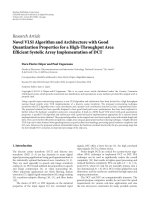
For the ODDs, the ontology importing feature w as used
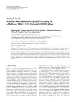
to build up a hier archical ontology layer architecture, which
can be seen in Figure 1. Arrows in this figure represent
import relationships between the different ontologies and
layers. Overall, four ontology layers are defined and used
for the specification of field and automation devices. Layer
1 contains the terminological ontologies, which define
the complete vocabulary of the ODDs. Layer 2 specifies
common, platform-specific instances such as processors,
transceivers or standard ty pes, which can be reused in all
EURASIP Journal on Embedded Systems 5
Sun tracking control
Set
temperature setpoint
Set
sunblind
Set
occupancy
Set
luminance setpoint
Measure
temperature room
Measure
humidity room
Measure
air quality
Function
Free
night cooling
Fan
control
Detect
occupancy
Automatic
light control
············
FunctionSensor
FunctionOperating
FunctionController
FunctionActuator
Actuate
sunblind
Actuate
light
Actuate
fan
Actuate
radiator
Figure 2: Taxonomy of functions.
ODDs of the corresponding platform. Layer 3 refines Layer
2 towards specific-manufacturers and adds definitions of
manufacturer specific types or profiles. Layer 4 finally bases
upon the definitions of all superior ontologies and contains
the individual device-specific ODDs as such, which are
platform and manufacturer specific.
This ontology layer architecture has been implemented
for the building automation domain, but can in principle
also be adopted for other domains such as industry or process
automation.AsspecificplatformforLayers2,3,and4,the
LON platform is used in the examples within this paper. In
the next sections, the four layers are described in more detail.
3.2.1. Layer 1 : Domain-Specific Vocabulary. The topmost
layer of the ontology architecture consists of the termi-
nological ontologies, which define the complete domain-
specific vocabulary. It is the only layer, where terminological
knowledge in form of OWL concepts, properties, annota-
tions, and constraints is defined. All other layers contain
instance definitions (assertional knowledge) only, which are
exclusively based on this domain-specific vocabulary.
For the building automation domain, there are three
terminological ontologies defined in Layer 1. The schema
ontology as the topmost ontology defines all general concepts
and corresponding properties, annotations, and constra ints,
such as the examples from Section 3.1. It enables the
definition of devices, t ransceivers, processors, manufactur-
ers, functional profiles, inputs, outputs, operation modes,
configuration parameters, semantics, and so on, along with
their descriptive datatype properties. And it defines the
structure of the object-oriented model, by relating these
classes via object properties.
Specific concept definitions, like the functions or I/O
modules of devices, are encapsulated in separate ontologies,
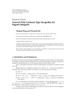
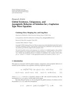
which extend the schema ontology. The functions ontology,
for example, defines a taxonomy of all building automation
functions, such as constant light control, automatic light
control, or presence detection, as can be seen in Figure 2.
They are classified in the four categories sensor, operating,
controller, and actuator by means of a concept hierarchy,
which is a fundamental instrument of ontologies. The func-
tions can be further described by datatype properties, such
6 EURASIP Journal on Embedded Systems
as the concept Constant
light control, that has the two
Boolean attributes, switchOnDelay and switchOffDelay,
which define whether the function supports a switch on and
switch off delay, respectively.
The separation in three ontologies is done for reasons
of a design workflow spanning usage and independent
development. Functions for example are not only used
for describing the functionality of devices, they are also
essential entities for describing functional requirements.
Thus, the functions ontology is also used in the initial stage
of requirement engineering [18]. And by using the same
vocabulary in both cases, an unambiguously direct mapping
of requirements to appropriate devices is possible in the
device selection phase, which is an important benefit.
3.2.2. Layer 2: Predefined Platform-Specific Data. Layer 2 of
the ontology architecture adds platform-specific instance
definitions to Layer 1. Again, this layer is separated in
several different ontologies. For the LON platform, these
are the hardware, LonMark standardizations, manufacturer,
and s emantics ontology. The hardware ontology for example
specifies all processors, transceivers, smart transceivers, and
transmission mediums that are relevant for the LON plat-
form, and the LonMark standardizations ontology defines
standardized LonMark profiles, network variable types, and
configuration parameter types together with all existing data
types.
Device manufacturers reuse these specifications in their
own ODDs by simply referencing them via object prop-
erties (e.g., ba:deviceManufacturer, ba:deviceTran-
sceiver). This referencing eases the specification process,
safes memory, and avoids duplicate specifications and incon-
sistencies.
3.2.3. Layer 3: Manufacturer-Specific Types. While Layers 1
and 2 were still manufacturer independent, Layer 3 focuses
on manufacturer-specific type and profile definitions. In
manufacturer-specific type definition ontologies, one for
eachmanufacturerandeachwithamanufacturer-specific
unique URI, all variable parameter and profile types of the
corresponding manufacturer are predefined as individuals.
Again, the individuals defined here can be reused by the
device manufacturers in their ODDs by referencing them,
with the same benefits as on Layer 2. For other platforms than
LON, Layer 3 may be omitted completely if the platform does
not support manufacturer-specific definitions.
3.2.4. Layer 4: Manufacturer-Specific Device Descriptions.
Layer 4 as the lowermost layer finally comprises the
individual platform and manufacturer-specific ODDs as
such. The ODDs employ the ontology definitions from the
superior layers, as explained before, by importing and using
them. Only the concepts from the Layer 1 ontologies (e.g.,
ba:Device, ba:Functional-Profile) are instantiated
here and assigned property values, which have not been
instantiated in the subordinate layers. For all other concepts,
the required individuals defined in Layers 2 and 3 are reused
by referencing them. This specification with the same ontol-
ogy vocabulary ensures a unified specification of all devices
and facilitates a manufacturer-spanning comparability and
retrieval of devices.
As appropriate partitioning, the assignment of one
ontology file for each device seemed to be the best choice.
This reflects the current state of the art prac tice in domain
engineering (cf. Section 1) and fits the prac tical demands at
the best. For each ODD, a globally unique URI is used. It is
composed from the manufacturer-specific URI extended by
a device-specific identifier.
3.3. Semantic Specification of Devices. Beside a comprehen-
sive specification of the hardware of building automation
devices, especially specific semantic knowledge about their
profiles is required for an automated design. This includes
knowledge about the specific functions implemented by each
profile (e.g., constant light control, automatic light control,
and occupancy control), how profiles should be parameter-
ized, what purpose their input and output datapoints have
(more precisely than standardized variable types allow for),
and how they can be connected appropriately.
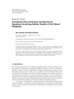
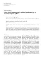
For this purpose, a semantic specification model has been
developed, which is integral part of the ODDs. Its application
is demonstrated in Figure 3 for the semantic specification
of a LON-based light controller profile. The syntac tical
definition of profile interfaces constitutes one part of the
model, as can be seen in the lower part of the Figure. As
in conventional electronic device descriptions, such as the
LonMark Device Interface (XIF) Files [6] or the binary
EIB/KNX description files, profile interfaces are described
by a set of input and output datapoints with corresponding
names and datatypes and a set of configuration parameters.
This profile interface layer is extended by a profile semantics
layer that adds the required semantics by means of four
key constructs: the operation modes, their parameterization,
functions, and semantic types.Itenablesasemanticallydeep
but at the same time easy-to-handle black box specification
of profiles, as will be explained in the following.
As many other profiles, the example profile in Figure 3
is quite advanced and supports multiple functions like
automatic light control, luminance-dependent automatic
light control, and constant light control, depending on its
parameterization. This change of the functional behaviour
needs to be expressed in the semantic model, which therefore
allows defining different operation modes for one profile
conditioned by parameters.
Figure 3 shows one of the three possible operation
modes, in which the profile realizes the function constant
light control. All possible functions, such as the func tion con-
stant light control itself, are defined in a function taxonomy,
as was explained in Section 3.2.1 (cf. Figure 2). Functions are
the most important device selection criteria for a function-
oriented automated design, where based on a functional
requirement specification full-functioning and complete
building automation systems are to be designed. Already
in the stage of requirement engineering, the functions
from the function taxonomy are used for the requirement
EURASIP Journal on Embedded Systems 7
Command switch light [C]
Command dim light absolute [C]
Function: Constant light control
switchOnDelay
= true
switchOffDelay
= true
Value luminance room [M]
SemanticTypes:
Parameterization: 0
cpClCtrlMode
cpLuxSetpoint
···
Light controller
nviLuxLevel
SNVT lux
nv1
nviSetting
SNVT
setting
nvoLampValue
SNVT
switch
nv5
nv2
nviManOverride
SNVT
switch
nv3
nviLuxSetpoint
SNVT
lux
nv4
Command activate controller [U
|C]
Command dim light relatively [U]
Optional:
Command switch light [U|C]
Command dim light absolute[U
|C]
Optional:
Value setpoint luminance room [U]
Operation mode 1:
Profile interface
Profile semantics
Figure 3: Interface and semantics of a light controller profile.
specification, which ensures an unambiguous mapping of
requirements to devices and corresponding profiles in the
later design phases.
The functions can have descriptive datatyp e properties
for a precise distinction of their semantics. The func-
tion constant light control from the example profile has
two Boolean datatype properties, the switchOnDelay and
switchOffDelay. Both are set to true, which indicates that
the profile realizes a constant light control with a switch-on
and switch-off delay in the given operation mode.
To select the shown operation mode, the configuration
parameter cpClCtrlMode needs to be set to 0, which is also
specified in OWL. This information can be used in the device
commissioning phase for an automatic parameterization of
profiles, which unburdens the system integrator from doing
it manually.
To define a precise meaning for input and output
datapoints far beyond standardized variable types, semantic
types are introduced. They are assigned to datapoints and
used to create semantically correct connections between dat-
apoints and to analyse the interoperability between profiles.
Semantic ty pes are predefined in the semantics ontology of
Layer 2 of the ontology layer architecture (cf. Figure 1)and
used via object referencing in the ODDs.
Besides the semantic types, input datapoints must be
declared as either mandatory, optional, or inactive for a
given operation mode. Mandator y inputs are essential for
a proper functioning of the profile and must be bound
with an interoperable output datapoint providing the desired
information. For example, the input datapoints nv1 (room
luminance level) and nv2 (occupancy state) in Figure 3 are
mandatory for the constant light controller. Optional inputs
on the contrary can be bound, but do not have to. They
provide additional information, such as nv3 (manual over-
ride from the user) or nv4 (luminance setpoint adjustment).
Inactive inputs must not be bound, because they are not
regarded by the profile in the given operation mode. Output
datapoints on the other hand are distinguished in active and
inactive. Only active outputs provide values and are possible
candidates for datapoint bindings. With that information, an
automated function-block-oriented composition of building
automation systems is feasible. Automated design algorithms
know which operation mode of a functional profile needs to
be selected for a desired functionality and which datapoints
of neighbored profiles are to be bound for a proper
functioning.
3.4. Ontology Standardization and Maintenance. For a broad
practical usage of the introduced ODDs, a functioning
business model and some kind of standardization committee
are required. The task of the standardization committee
would be to provide an extensive and generally accepted
catalogue of definitions for Layers 1 and 2, which alto-
gether constitute a common semantic base and uniform
8 EURASIP Journal on Embedded Systems
sp:DEV 58 90003A82003F0411
Lumina RDA2
ba:deviceName
20
ba:deviceIngressProtection
90003A82003F0411
ba:deviceSPID
ba:deviceMountingForm
ba:Cap
rail mounting
ba:deviceProcessor
hw:Neuron 3150
ba:deviceProfile
ba:deviceProfile
sp:FP
58 21400 3 2 11 485
sp:FP
58 21502 4 1 11 465
Figure 4: Basic RDF graph.
specification framework for a given domain and platform.
The ontologies of the manufacturer-specific Layers 3 and
the ODDs as such (Layer 4) on the contrary should be
specified by the device manufacturers, as is common practice
in domain engineering. All device manufacturers are obliged
to specify their devices according to the definitions from
Layers1and2only.
Whenever new hardware is available or the existing
standard profiles, standard variable types, functions, and so
forth need to be expanded, it should be the standardization
committee’s task to extend and adopt the ontologies and
provide them to all manufacturers. The developed ontology
architecture is very flexible for extensions of this kind. New
concepts, properties and individuals can in contrast to XML
or database schemata be added easily to the upper two
ontology layers, without any negative effect on the existing
ODDs (forward compatibility).
Altogether, the introduced device description approach
provides a formal, extensible, manufacturer-independent,
and machine-readable specification format, as it is required
for design automation. It enables a deep, unified specification
of devices from different domains and platforms and thus
ensures comparability of different devices. The ODDs are
furthermore particularly suitable for a comprehensive spec-
ification of the hardware and software of devices, including
also their functionality and characteristics necessary for
a function-oriented design and automated interoperability
evaluation.
4. Generic Ontology Views and Data Access
As shown in Section 3, the ODDs define a variety of different
information for each device, ranging from hardware criteria
to the software applications and their semantics. Users and
the automated design algorithms must be able to access and
search this information in an adequate and flexible way.
Depending on the specific application scenario, a device
catalogue tool, a search mask, a device editor, or an automatic
design tool, different demands exist. Data could be needed
only in extracts or as a whole or in a different aggregation as
in the underlying model.
To face this variety of possible demands in a flexible way,
a generic ontology view concept, virtual ontology properties,
and generic data access mechanisms have been developed.
They enable the flexible definition of user-specific views on
the ODDs and their transparent access via a generic interface.
These approaches will be explained in the following sections.
4.1. Ontology View Approach. In database theory, a view
describes resources of interest to a user in form of virtual
tables that are not part of the physical schema, but computed
or collated from data in the database. Views can b e used for
example to represent a subset of the data contained in a table
or they can join and simplify multiple tables into a single
virtual table. They thus can hide complexity of the data and
provide abstraction.
Such a view concept would be also very beneficial for
ontologies. Compared to databases, however, ontologies rely
on a different underlying data model, namely, RDF. In
RDF, all information is represented in form of triples that
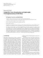
altogether form a complex RDF graph. An example RDF
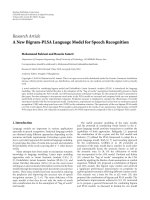
graph can be seen in Figure 4. This RDF graph shows
a device individual sp:DEV
58 90003A82003F0411 of an
ODD along with some of its properties in RDF pictorial
representation. Resources (subject or object) are represented
as green ellipses, predicates as directed arrows originating
at the subject and pointing to the objec t, and literal values
are drawn as orange rectangles. Note that the figure only
shows a small excerpt from the complex RDF graph of the
corresponding ODD.
Via the three datatype properties ba:deviceName,
ba:deviceIngressProtection, and ba:deviceSPID
the name of the de vice (“Lumina RDA2”), its ingress
protection (20), and its standard program ID (“900-
03A82003F0411”) are defined. Furthermore, the enu-
merated property ba:deviceMountingForm defines that
the mounting form is cap-rail mounting. The device
has two functional profiles, defined via the object prop-
erty ba:deviceProfile and corresponding individu-
als of the concept ba:FunctionalProfile, of which
sp:FP
58 21502 4 1 11 465 represents the light con-
troller profile from Figure 3. The processor of the device
EURASIP Journal on Embedded Systems 9
sp:DEV 58 90003A82003F0411
Lumina RDA2
ba:deviceName
20
ba:deviceIngressProtection
90003A82003F0411
ba:deviceSPID
ba:deviceMountingForm
ba:Cap
rail mounting
ba:deviceProcessor
hw:Neuron 3150
ba:deviceProfile
ba:deviceProfile
sp:FP
58 21400 3 2 11 485
sp:FP
58 21502 4 1 11 465
Figure 5: Hardware-specific view on the RDF graph e xample.
(object property ba:deviceProcessor) is the individual
hw:Neuron
3150 from the hardware ontology of Layer 2 of
the ontology layer architecture (cf. Figure 1).
Ontology v iews and views on RDF graphs are an
important research topic in the semantic web community.
Adequate view concepts are of major importance for a wide
acceptance and usability of the semantic web. They are
needed to provide users an appropriate, use case-specific
excerpt of the potentially very complex ontologies, which
otherwise are too complex for a proper orientation and
understanding. Various approaches for the specification of
ontology views exist in parallel, and till now, there is no
standard way for a proper view specification.
A popular approach is the definition and application
of a view definition language. Reference [19], for example,
introduces RVL (RDF View Language), an expressive view
definition language, which is based on the query language
RQL (RDF Query Language). RVL provides users with the
ability to define a view in the same way in which they
write normal RDF/S schemas and resource descriptions.
It is capable of creating virtual resource descriptions, but
also virtual RDF/S schemas from concepts, properties, as
well as resource descriptions available on the semantic
web. Reference [20] on the contrary introduces CLOVE
(Constraint Language for Ontology View Environments), a
high-level constraint language that extends OWL constraints.
CLOVE allows the dynamic creation of view classes based on
complex logical conditions, supports inheritance of views,
and also incorporates user role definitions and access rights.
Other ontology view approaches rely on graph-based
constraints, instead of view definition languages. In [21], the
concept of traversal views is defined. A traversal view is a
view where a user specifies the central concept or concepts of
interest, the relationships to traverse to find other concepts
to include in the view, and the depth of the traversal. It thus
defines views by forming clusters of neighbored nodes of an
RDF graph that surround a given central concept.
In contrast to existing ontology view approaches, which
rely on view definition languages or graph-based approaches,
we developed and introduce a much simpler, easy-to-handle,
and quite effective ontology view concept. We disclaim on
the introduction and application of a specific language
but extend the ontologies by a view definition. This view
definition lists all available concepts together with their
associated datatype and object properties in an XML-based
document and allows the concept-specific declaration of
view specific identifiers for each property, thus declaring
their membership for the individual views.
Considering the graph from Figure 4,specificontology
views can be defined by declaring the datat ype and object
properties of certain concepts as members of a specific view.
For demonstration purposes, two different views are defined,
a hardware and a software-specific one. T he hardware-
specific view on the one hand considers the hardware aspects
of devices, such as the processor, mounting form and ingress
protection and owns the view identifier “hw1.” The software-
specific view with the view identifier “sw1” on the other
hand hides hardware characteristics and focuses mainly on
the functional profiles of the device.
Figures 5 and 6 show the resulting view-specific RDF
graphs. The visible edges and nodes in the graphs represent
the datatype and object properties that are labeled with the
view-specific identifier “hw1” (Figure 5), respectively, “sw1”
(Figure 6) in the view definition. The greyed out graph
elements are not visible in the specific view but only shown
for a better illustration. ba:deviceName is labeled with both
identifiers and thus belongs to both views.
4.2. Virtual O ntology Properties. Along with the ontology
view approach from the last section, another key concept is
introduced for a flexible and generic data access mechanism.
It is the concept of virtual properties that are used to establish
shortcuts in the RDF graph. Virtual properties do not exist
as real properties but are virtual and computed on demand.
We introduce two kinds of virtual properties: virtual object
properties and virtual datatype properties.
Virtual object properties on the one hand form the
transitive closure over t wo or more interlinked object
properties and thus connect two nonadjacent concepts
with each other. An example of a virtual object property is
shown in Figure 7. In this RDF graph, the device individual
10 EURASIP Journal on Embedded Systems
sp:DEV 58 90003A82003F0411
Lumina RDA2
ba:deviceName
20
ba:deviceIngressProtection
90003A82003F0411
ba:deviceSPID
ba:deviceMountingForm
ba:Cap
rail mounting
ba:deviceProcessor
hw:Neuron
3150
ba:deviceProfile
ba:deviceProfile
sp:FP 58 21400 3 2 11 485
sp:FP 58 21502 4 1 11 465
Figure 6: Software-specific view on the RDF graph example.
sp:DEV 58 90003A82003F0411
ba:deviceProfile
sp:FP
58 21502 4 1 11 465
ba:profileOperationMode
ba:profileOperationMode
ba:operationModeFunction
sp:Automatic
light1
ba:operationModeFunction
sp:Constant
light control1
sp:opMode2
ba:deviceFunction
ba:deviceFunction
sp:opMode1
Figure 7: Virtual object property example.
from the previous figures and one of its functional profiles,
the light controller from Figure 3, are shown. According
to the semantic specification model (cf. Section 3.3), the
functionality of the profile is defined via instances of the
class ba:OperationMode. Each operation mode defines one
or more functions that are realized by the profile in the given
operation mode. The function individuals are instances of
the concepts from the function taxonomy in Figure 2. In the
example in Figure 7, the individual sp:Automatic
light1
is an instance of comms:Automatic
light control
and sp:Constant
light control1 is an instance of
comms:Constant
light control. Altogether, this defines
that the profile implements an automatic light, respectively,
constant light control in its operation modes.
For being able to directly query the functions that a
device as sum of its profiles and corresponding operation
modes implements, a virtual object property can be defined.
The v irtual object property ba:deviceFunction expresses
this relation as transitive closure of the object property
chain ba:deviceProfile, ba:profileOperationMode
and ba:operationModeFunction. By querying all values
of ba:deviceFunction, the user gets immediately all
functions implemented by the device without the need to
navigate to all functional profiles, furthermore to all their
operation modes and finally to all their functions.
Virtual datat ype properties, on the other hand, relate
datatype properties of distant concepts via the transitive
closure over one or more object properties with a given
concept. This means that a datatype property, which origi-
nally belongs to a different concept, is directly related with a
concept as if it would belong to it.
An example for a virtual datatype property is demon-
strated in Figure 8. The datatype property ba:manu-
facturerName, which belongs to the concept ba:Manu-
facturer, is related as virtual datatype property ba:
deviceManufacturerName with the concept ba:Device.
Virtually, it is now a datatype property of the device itself
and can be queried directly for the given device, instead of
navigating to the manufacturer individual and then further
to the literal value of ba:manufacturerName.
In addition, the relation ba:deviceManufacturer can
be hidden in a corresponding ontology view definition, for
example, ontology view “hw1,” whereby the manufacturer
concept and all its properties are excluded from the model as
is illustrated in Figure 8. Thus, the user never needs to get in
touch with the manufacturer concept but he uses the virtual
datatype property ba:deviceManufacturerName instead.
Virtual properties are declared by using OWL annotation
properties. Annotation properties can be used to add metain-
formation to resources, be it a concept, datatype property,
EURASIP Journal on Embedded Systems 11
sp:DEV 58 90003A82003F0411
Spelsberg building automation
ba:manufacturerName
ba:deviceManufacturer
ma:Spega
58
ba:manufacturerLonMarkID
ba:deviceManufacturerName
Figure 8: Virtual datatype property example.
object property, or individual. For our purposes, we
defined two annotation properties, ba:virtualDatatype-
Property and ba:virtualObjectProperty, within
Layer 1 of the ontology layer architecture (cf. Figure 1).
They are used to define the virtual property definitions.
Virtual propert y definitions are annotated to the OWL
concepts, where the virtual properties start from. The
specification includes the URI of the virtual property, the
path to the destination property and multilingual names
and descriptions. Like all datatype and object properties,
virtual datatype properties and virtual object properties can
also be declared as members of ontology views in the view
definition. In this example, ba:deviceManufacturerName
is declared as member of the ontology view “hw1.”
The combination of ontology views and virtual prop-
erties can span completely new virtual terminological layers
over existing RDF graph, simply by editing the view defi-
nitions and by introducing virtual properties. This enables
very flexible, easily customizable, and object-oriented views
on the underlying ODDs according to requirements. It is a
very powerful mechanism for creating generic ODD tools
uncoupled from the underlying ontologies, such as generic
ODD editors [22], search masks, or device browser that are
easily adoptable to user-specific needs without changing the
program code.
4.3. Generic Data Access. As the last, two sections have
shown, ontology views and virtual properties provide an
effective way for virtually adopting the structure of RDF
graphs for user and tool-specific views. What is still an
open issue is the question on how an adequate access to the
ontology data can be provided, without the need to get in
touch with all the details of views and virtual properties.
For this purpose, a gener ic data access interface is defined
and implemented that provides a ccess on the underlying
ontology data. It consists of a set of generic data access
methods whose implementation is detached from the specific
underlying ontologies. Two generic terminological methods
enable to list all datatyp e, respectively, all object properties
for a given concept under regard of a given view identifier.
No difference is made here whether the properties are real or
virtual, this is deliberately hidden behind the interface. Vir-
tual properties are thus treated as if they were real properties,
and they look the same for the user. All information required
is contained in the terminological ontologies from Layer 1
(cf. Figure 1) and extracted from there. For the hardware-
specific view “hw1” (cf. Figures 5 and 8) and the concept
ba:Device for example, the datat ype properties ba:dev-
iceName, ba:device-IngressProtection, ba:device-
Mounting-Form, ba:deviceManufacturerName (virtual
property), and the object property ba:deviceProcessor
are returned.
Two generic assertional methods then allow for querying
the values of a given individual for a given datatype or
object property respectively, no matter whether it is a
real or virtual property. Here, device-specific information
defined in the ODDs needs to be accessed and returned.
This can be done via direct property access or SPARQL-
Queries, as will be explained later on in Section 5.3.As
an example, again consider the RDF graph from Figure
5. For the individual sp:DEV
58 90003A82003F0411 and
the datatype property ba:deviceName the assertional
method returns “Lumina RDA2”. For the (virtual) property
ba:deviceManufacturerName (cf. Figure 8) the method
returns “Spelsberg Building Automation”. Given the object
property ba:deviceProcessor or ba:deviceFunction,
the object property-specific assertional method returns the
individuals hw:Neuron
3150 and sp:Automatic light1,
sp:Constant
light- control1, respectively.
These four methods thus enable to browse the whole
RDF graph in a generic way, detached from the concrete
underlying ontologies. Starting from an individual, at first
all datatype and object properties of the individual’s concept
for a specific view can be requested. Further terminological
methods are contained in the generic data access interface
that can be used for requesting the datatype of datatype
properties, the r ange of object properties, the multilingual
names and descriptions of concepts and properties, and so
on. The terminological methods thereby provide the means
12 EURASIP Journal on Embedded Systems
for accessing the terminolog ical knowledge of the ODDs,
the semantics of the ontologies, encapsulated in the Layer
1 ontologies. This is an important advantage compared to
relational databases, where the semantics of the data is not
explicitly available and accessible, but hidden within the
design of the database tables.
Then, after querying all datatype and object proper-
ties of an individual, their values can be accessed with
the assertional methods. Whereas the values of datatype
properties are literal values, objec t properties on the other
hand point to other individuals. Then, for each individual,
again all corresponding view-specific datatype and object
properties can be requested and their values can be queried.
In this way, the whole view-specific RDF graph incorporating
virtual properties can be browsed step by step. Object-
oriented device browsers for displaying the characteristics
of devices, such as web-based device catalogues, can easily
be implemented b ased on this generic interface. By using
the interface, the tools are detached from the concrete
underlying ontologies. Changes in the terminolog ical or
assertional knowledge do not require any changes in the tool
implementations.
5. Triple Store-Based Device Repository
For handling and storing the ODDs, which were introduced
in Section 3, a persistent, flexible, and efficient database
technology is required. The database should be able to
handle large datasets (i.e., thousands of devices) and perform
efficient data access and queries, for example, for accessing
device properties, for querying for devices that match certain
requirements, or for estimating their interoperability. It
must also be able to cope with ontology views and virtual
properties as explained in Section 4.
As mentioned before, the basic underlying data units of
OWL are RDF tripel that together form an RDF graph. RDF
graphs can be stored in specialized databases, called RDF
triple stores, also abbreviated as RDF stores or triple stores.
RDF triple stores enable the management of large graphs
and their querying with the query language SPARQL [23]
(see Section 5.3). They typically consist of a query framework
and underlying backend. Jena and Sesame are two widely
accepted and mature query frameworks, amongst a variety
of others like 3store, RDFSuite, and Openlink Virtuoso. Most
triple stores use a relational database management system as
backend to manage RDF data [24]. Alternatively, they can
rely on in-memory implementations or on native persistent
storage systems with their own implementation of databases.
Triple stores are capable of handling very large datasets of
more than one billion triples [25], which continuously grows
with new hardware and better optimized triple stores. The
largest known triple store yet has been implemented with
BigOWLIM and can handle 20 billion statements, running
on a single server [26]. It is believed that “future RDF triple
stores will be used as backends for application systems in
analogy to existing relational databases” [27], which shows
the relevance of triple stores as technology of the semantic
web, known as Web 3.0, for the future.
Table 1: The schema-oblivious database layout.
Subject
(resource URI)
Predicate
(property URI)
Object (Literal
value or
resource URI)
··· ··· ···
5.1. Database Representation of RDF. Existing RDF triple
stores employ a variety of storage schemas. “The most pop-
ular database representations for shredding RDF/S resource
descriptions into relational databases are: the schema-
oblivious (also called generic or vertical), the schema-aware
(also called specific or binary)andahybrid representation,
combining features of the previous two” [28]. The difference
in the three approaches lies in the definition and usage of
different table designs for holding the RDF triples. While the
schema-oblivious approach uses only one table for storing
all triples (the triples table, see Ta ble 1 ), the schema-aware
uses separate tables for each property and for each class. The
hybrid approach in turn uses one table per property instance
with different range value, and overall one table for all class
membership definitions.
The open source framework Jena SDB [29], which is
used in our implementations, relies on the schema-oblivious
approach. This ensures a maximum flexibility for on-the-
fly extensions by further classes and properties, without the
need for adding or deleting tables, which is necessary in the
schema-aware approach.
RDF triple stores readily manage the concept of optional
data. In OWL and RDF, it is not assumed that complete
information about any resource is available. It is convenient
to omit values which are not known or not of interest.
Missing property values in a relational database, however,
require null values in the corresponding database table and
still require storage space. The possibility of null values
complicates the definition of SQL queries, which makes
SQL a bit awkward for use in dealing with less str uctured
information. In RDF, however, the corresponding triple
simply not exists and no null values must be inserted, which
does not consume storage space. RDF triple stores are thus
much better suitable for semistructured data with optional
information than relational databases with their rigid table
structure.
5.2. Triple Store Architecture and Management. Jena SDB as
our underlying triple store framework relies on the schema-
oblivious approach; that is, it uses one database table to
store all RDF triples. Thus, all ontologies of the layer
architecture from Figure 1, including all device descriptions,
one ontology file per device, are serialized as RDF-Triples and
stored altogether as triples in the same triples table, as shown
in Figure 9. The triple table is managed by the RDF triple
store that forms the device repository. It contains all device
descriptions and enables data access and retrieval operations,
as will be shown in the next sections.
To fill the device repository with data and to manage
its contents, basically two operations are needed: adding
devices to the device repository and deleting devices from the
EURASIP Journal on Embedded Systems 13
Processors
Transceivers
Smart transceivers
Mediums
Adresses
Contact information
Concepts and
properties for
BA functions
Var ia bl e ty pe s
Parameter types
Variable types
Parameter types
Standard profiles
Standard variable types
Standard parameter types
Data types
Hardware
Manufacturers
LonMark standardizations
Schema ontology
Type definitions Type definitions
Device
Functional profiles
Parameters
Functions
Device
Functional profiles
Parameters
Functions
Device
Functional profiles
Parameters
Functions
Device
Functional profiles
Parameters
Functions
Device 1 Device 1
···
······ ···
Concepts and
properties for
Semantic types
Semantics
ODD ODD ODD ODD
Subject
URI Ind 1
URI Ind 1
URI Ind 3
Predicate
URI Prop A
URI Prop D
URI Prop G
Object
URI Ind 3
20
URI Ind 6
··· ··· ···
General concepts, properties
annotations, constraints
Inputs, outputs Inputs, outputs Inputs, outputs Inputs, outputs
I/O modules
I/O modules I/O modules I/O modules I/O modules
RDF triple store
RDF-
triple
Manufacturer A Manufacturer Z
Device m
Device n
Layer 2:
Predefined
platform-specific
data
Layer 4:
Platform- and
manufacturer-specific
device descriptions
Layer 1:
Domain-specific
vocabulary
Layer 3:
Platform- and
manufacturer-
specific types
Figure 9: Triple store-based device repository.
device repository . Both operations are very easy to realize as
triple store. The adding operation simply loads one or more
ODDs, parses them into RDF triples, and sends all triples to
the database, which stores them in the triples table. If the
database has not yet been initialized also the ontologies from
Layers 1, 2, and 3 need to be added initially.
Since each ODD owns a unique URI, the deleting
operation of devices from the device repository simply
consists of deleting all the triples, whose subject or object
URI contains the device-specific URI. With that easy-to-
implement operation, it is ensured that a device and all
references to it are completely removed from the repository.
5.3. Querying the Device Repository. Once a database has
been initialized with ODDs, mechanisms are required to
access or retrieve the information contained in the device
repository. Technically, two different access mechanisms are
possible. In case of a given individual, its property values
can be accessed directly via specialized get methods of the
Jena SDB API, which is the fastest accessing mechanism.
This works for real datatype and object properties, but
not for virtual properties. Secondly, the available device
repository can be queried with SPARQL queries. SPARQL
[23] is an easy to handle graph-based query language that
allows querying RDF graphs similar like SQL can do with
relational databases. SPARQL queries typically define graph
patterns that are to be matched with given ontologies.
Every infor mation defined in the RDF model, namely, all
instances and their datatype and object properties, can be
referred.
14 EURASIP Journal on Embedded Systems
SELECT DISTINCT ?x1 WHERE {
?x1 a ba:Device.
?x1 ba:deviceIngressProtection ?x2.
FILTER (?x2 >= 20).
?x1 ba:deviceOperatingVoltage ?x3.
FILTER (?x3 = ba:DC
24 V||
?x3 = ba:AC
24 V).
?x1 ba:deviceMountingForm ?x4.
FILTER (?x4 = ba:Surface
mounting ||
?x4 = ba:Cap
rail)}
Algorithm 1: A simple SPARQL query.
Simple SPARQL queries can also be used to query the
properties of given individuals, such as the properties of a
certain device. Beyond that SPARQL can do much more.
More complex queries can be formulated and executed that
query the whole database for suitable devices in the pool of
all existing, thereby realizing the essential step of mapping
requirements to suitable device candidates. For example, it
is possible to formulate a query that selects all devices with
required device properties, which have a transceiver with
certain properties, and which contain a profile that realizes
two specific functions with corresponding properties.
An example of a simple SPARQL query is shown in
Algorithm 1. The query selects all devices, which have an
ingress protection of at least 20, an operating voltage of either
“24 V DC” or “24 V AC” and which have the mounting form
“surface mounting” or “cap rail.”
Furthermore, SPARQL queries are used to query the
values of virtual datatype and object properties for the
generic assertional methods (cf. Section 4.3). Since virtual
properties form the transitive closure of several object
properties, a SPARQL query for resolving the values of a
virtual property consists of a chain of these object properties
and corresponding variables. The queries are generated
dynamically on demand according to the OWL annotations
that define the virtual properties. To be processed by a
relational DBMS, SPARQL queries are transformed to SQL
queries, which can then be optimized and evaluated by the
relational query engine. Efficient translation algorithms are
available and integral part of RDF triple stores, which will
be even further improved in the future by ongoing research
[24].
5.4. Generic SPARQL Query Generation. To disburden the
users from writing SPARQL queries themselves, search masks
should be provided for editing device search criteria. Based
on the generic data access interface introduced in Section 4.3,
generic search masks can be implemented that provide the
user a comfortable GUI and that generates and executes
SPARQL queries at the push of a button. An example
implementation based on our ontology view concept and
following a tab-based approach is shown in Figure 10.The
search mask is initialized according to a specific view and
displays the terminological knowledge specific for the view.
Each tab represents a certain concept and contains all its
datatype proper ties that are members of the view, including
also virtual datatype properties. The user can edit each
datatype property and define values that the required devices
must fit either and- or or-related, or that devices must not fit.
Neighbored concepts, which are related to the concept via an
object property, be it a real or virtual one, are displayed in
neighbored tabs with hierarchically subordinated tabs, each
of it representing further neighbored concepts. It enables the
object-oriented definition of complex device requirements
such as for the retrieval of all devices with certain properties
that have two functional profiles with certain properties, and
which implement a specific function.
Thesearchmaskisbasedonacompletelygeneric
architecture, detached from the particular ontology data.
Its hierarchical tab-folder structure, the contained datatype
property fields, the allowed range values of enumerated
string properties, the names, labels, and all tool-tip descrip-
tions stem from the ontology data loaded via the generic
access interface during initialization. Simply by changing the
underlying ontology model the search mask appears in a
new adapted layout with its next execution, without the need
for modifying its program code. One can even replace the
whole ontology model by another one that describes another
platform, such as EIB/KNX or EnOcean instead of LON.
Then, you immediately get an EIB/KNX or EnOcean-based
device search mask without any program modifications.
At the push of the search button a SPARQL query is
dynamically generated in the background by a specialized
query-generation algorithm. The query generation algo-
rithm collects all user-defined device requirements and
builds a SPARQL query that combines all requirements
into a single query. A specific challenge here poses the
transformation of the view-based virtual terminological layer
based on virtual properties into the actual structure of the
underlying RDF graph, which is done in a complex query
optimization routine.
Once generated, the SPARQL query is executed by the
RDF triple store. Results of the database retrieval operation
are then displayed in table form in the lower part of the
search mask.
5.5. Scalability and Pe rformance. In this section, results from
scalability and performance tests of our device repository
implementation are shown. The tests will show how the
triple store is able to cope with large amounts of data and
how the device retrieval operations perform under different
circumstances.
The implementation is based on Java and Jena SDB [29]
with the object relational DBMS PostgreSQL as database
backend. The test hardware used in this study was a system
with two Quad Core Intel XEON 5530 Processors running at
2.5 GHz, 16 GB of RAM, 500 GB of storage disk space, and
Linux as operating system.
As test dataset the building automation domain was
chosen with the ontology architecture from Figure 1 and
LON-specific ontologies on the layers 2 and 3. The ontologies
from Layer 1 comprise overall 133 OWL concepts, 46 OWL
object proper ties and 100 OWL datatype properties. The
EURASIP Journal on Embedded Systems 15
Figure 10: Generic search mask GUI.
Layer 2 ontologies add 742 LON platform-specific OWL
individuals to this terminological data, and the ontologies
from Layer 3 additionally add 2.247 manufacturer-specific
individuals for the type definitions of six manufacturers.
Altogether, the ontologies from Layers 1 to 3 of the ontology
layer architecture make up 25.551 triples, which form the
unified ontology vocabulary and basic dataset for all test
databases.
39 different ODDs for LON devices from different man-
ufacturers with overall 79 functional profiles on the devices
constitute the original dataset for Layer 4. Whereas the least
complex device with one functional profile comprises 122
triples only, the most complex device equipped with nine
different functional profiles sums up to 1.368 triples. All 39
devices and 79 functional profiles together comprise 11.905
triples.
For performance and scalability tests with large data
volumes, the 39 device descriptions and corresponding
functional profiles were renamed and duplicated by factors
10, 100, and 1.000, thus resulting in four different databases.
These are the original database with 39 devices, a medium-
sized database with 390 devices, a large-sized database
with 3.900 devices and a very-large-sized database with
39.000 devices. Tab le 2 shows the characteristics of the four
databases in number of devices, number of profiles, number
of triples, and database size in MB. The largest database
reaches a dimension of more than eleven million triples and
a size of more than two GB.
Table 2: The four different device repositories.
Database Devices Profiles Triples Size
Original 39 79 37.456 13 MB
Medium 390 790 144.601 32 MB
Large 3.900 7. 900 1.216.051 223 MB
Very large 39.000 79.000 11.930.551 2.200 MB
Table 3: Performance and scalability test results.
Database
Direct
property
access
SPARQL
property
access
Simple
SPARQL
query
Complex
SPARQL
query
Original
1,83 ms 5,38 ms 19,3 ms 364,1 ms
Medium
2,07 ms 5,78 ms 52,3 ms 521,6 ms
Large
2,49 ms 5,86 ms 379,7 ms 1.299,3 ms
Very l ar ge
3,52 ms 6,14 ms 2.175,4 ms 5.245,9 ms
The four databases underwent different tests to compare
their performance with e ach other. Four different use cases
are presented in the following, which regard the different
possible database accessing mechanisms. All tests were
executed 40 times, and their average response times in
milliseconds are summarized in Ta ble 3 .
16 EURASIP Journal on Embedded Systems
The first column shows the test results of a direct
property access via the specialized get methods of the Jena
SDB API. Given an individual URI and a corresponding
property, all related property values are queried. As the
results show, this takes on average no longer than two till
four milliseconds for the four databases. It is remarkable that
the size of the database, be it 37.456 or 11.930.551 triples,
has only a slight influence on the response times, which
approximately double from 1,83 ms to 3,52 m s for thousand
timesmoredevices.
The second column presents the results of a more com-
plex property access based on a SPARQL-query, such as for
querying the values of a virtual property. An example is the
virtual datatype property ba:deviceManufacturerName
from Figure 8 for a given device individual. This kind of
access requires the navigation from an individual along an
object property to a neighbored individual and finally the
access of the corresponding datatype property values. Again,
this access mechanism turns out to be very efficient, even
if the response times are approximately increased by factor
2 compared to the direct property access. The increasing
size of the four databases only slightly increases the query
response times, from the smallest to the largest database by
only 14,1%.
The third and fourth columns show the query response
timesfordeviceretrievaloperationswithtwoalternative
SPARQL queries, a simple and a complex one. The simple
query is the query shown in Algorithm 1 (see Section 5.3).
This query contains one select variable, overall four variables,
three different properties and three FILTER constructs. The
complex query additionally regards twelve further properties
of the device, such as certain transmission mediums, or the
functions of its functional profiles with certain attributes.
It overall contains seven select variables, thirteen variables,
fifteen different properties, and four FILTER constructs.
As the results show, the query response times correlate
with the size of the particular database. Whereas the simple
query for the smallest database requires 19 ms, it requires for
the largest database 2.175 ms, which is a difference of factor
114. But this is still less than the factor of 318 between the
numbers of triples of both databases. For the complex query,
the factor between the smallest database (0,36 s) and the
largest database (5,2 s) is much smaller and amounts to only
14. This indicates that the query response times scale with an
increased database size with at most linear time complexity.
It ensures a good scalability for arbitrary complex databases
and an instantaneous performance gain on better hardware.
6. Conclusions
In this paper a pure ontology-based device description
approach for automation devices based on OWL and
RDF, the ODDs, was introduced. Along with a layered
ontology architecture, the ODDs enable an easy, formal,
object-oriented, machine-readable, and unified specifica-
tion of building automation devices of different platforms.
The vocabulary can be easily extended by further classes
and properties and ensures a comparability of different
devi ces. The approach is suitable for specifying all kinds of
information, ranging from device hardware characteristics
to a deep semantic specification of software applications,
including their operation modes and parameterization. Also,
all characteristics that affect the interoperability of devices
can be expressed, which enables an automated algorithmic
interoperability evaluation.
Furthermore, a combination of ontology views and
virtual properties has been introduced, that enables cus-
tomizable, object-oriented views on the underlying ODDs.
Transparent data access is provided by a generic access
interface which hides the complexity of views and virtual
properties. Generic ODD tools can be implemented based
on the interface such as ODD editors, search masks or device
browser, that automatically adopt to the underlying ontology
data.
Along with the ODDs and generic access interface, a
persistent device repository implemented as RDF triple store
was introduced. The device repository affords an efficient
data access and automatic device retrieval, is capable of
handling large sets of devices and shows a good scalability,
as test results with up to 39.000 devices have shown.
The presented approach finally overcomes the draw-
backs of existing device descriptions by facilitating a w ide
range of essential automatic operations such as for device
retrieval, operation mode selection, device parameterization,
and automatic interoperabilit y evaluation. This altogether
enables an automated design of building automation sys-
tems, w hat can strongly reduce the design time, design costs,
and finally the overall costs for building automation systems.
Thereby, the amortization is achieved earlier, which should
promote an increased number of installations in the future
and contribute to further energy savings in buildings.
Ongoing and future work covers several topics related
to the ODDs. Beside generic ODD editors, which have been
introduced in [22], also automatic mechanisms for validating
the created ODDs are required in practice to ensure valid
specifications. Research is being spent on reasoning-based
approaches for consistency and completeness checks of
ODDs. Reasoning is applicable since OWL as the underlying
specification language is a formal logical language that
directly supports reasoning, which is a major advantage of
OWL.
Otherworkwillcoverapproachesforanautomatic
interoperability evaluation of devices of different platforms,
which includes the automatic retrieval of suitable gateways
that can bridge the communication between the different
technologies.
Last but not least, a hierarchical, platform-independent
device requirement specification and device retrieval is under
development. It is going to enable a user-controlled, stepwise
definition of device criteria that can be matched against
ODDs of different platforms. This would enable an impor-
tant change in the design process of automation s ystems: the
decision for using a specific technological platform can be left
open to later design phases, where all requirements are finally
known. Then, the optimal technological platform(s) can be
estimated at the end, thus providing the best technological
conditions for the automation systems to be designed.
EURASIP Journal on Embedded Systems 17
Acknowledgments
The ODDs and the device repository have been developed by
the Dresden University of Technology along with industrial
partners within the research projects AUTEG (promotional
reference 16IN0405), funded by the German Federal Min-
istry of Economics and Technology, and AUDRAGA (promo-
tional reference 01BN0908), funded by the German Federal
Ministry of Education and Research, due to a decision of the
German Parliament (see for both
projects).
References
[1] A. C. Oezluek, H. Dibowski, and K. Kabitzsch, “Automated
design of room automation systems by using an evolution-
ary optimization method,” in Proceedings of the 14th IEEE
International Conference on Emerging Technologies and Factory
Automation (ETFA ’09), Mallorca, Spain, September 2009.
[2] H. Dibowski and K. Kabitzsch, “Ontology-based device
descriptions and triple store based device repository for
automation devices,” in Proceedings of the 15th IEEE Inter-
national Conference on Emerging Technologies and Factory
Automation (ETFA ’10), Bilbao, Spain, 2010.
[3] ANSI/ISA-61804, “Function Blocks (FB) for Process Control
– Part 3: Electronic Device Description Language (EDDL),”
2007.
[4] CAN in Automation, “CANopen—overview,” http://www
.canopen.org/.
[5] ISO 15745, “Industrial automation systems and integration—
open systems application integration framework, part 3:
reference description for IEC 61158-based control systems,
Std.,” 2003.
[6] Echelon Corporation, “LonMark Device Interface File Refer-
ence Guide,” Revision 4.401, 2005, />JobAids/LmXif4401.pdf.
[7] ETIM Deutschland e.V., “Datenmodell ETIM Klassifikation-
ssystem 4.0,” 2008, />[8] eCl@ss e.V., “eCl@ss 6.xx,” 2010, assdown-
load.com/.
[9] PROLIST INTERNATIONAL e.V., “PROLIST,” http://www
.prolist.org/.
[10] Foundation for Intelligent Physical Agents, “FIPA Device
Ontology Specification,” 2001, http://www.fipa.org/specs/
fipa00091/PC00091A.html.
[11] World Wide Web Consortium (W3C), “Resource Description
Framework (RDF),” 2004, />[12] World Wide Web Consortium ( W3C), “RDF/XML Syn-
tax Specification (Revised),” W3C Recommendation, 2004,
/>[13] World Wide Web Consortium (W3C), “OWL 2 Web Ontol-
ogy Language Document Overview,” W3C Recommendation,
2009, .
[14] World Wide Web Consortium (W3C), “CC/PP Information
Page,” 2007, />[15] World Wide Web Consortium (W3C), “Device Descrip-
tion Repository Simple API,” W3C Recommendation, 2008,
.
[16] WURFL, “Welcome to the WURFL,” 2010, http://wurfl
.sourceforge.net/.
[17] Open Mobile Alliance, “OMA User Agent Profile V2.0,”
2007, />program/uap v2 0.aspx.
[18] S. Runde, H. Dibowski, A. Fay, and K. Kabitzsch, “A semantic
requirement ontology for the engineering of building automa-
tion systems by means of OWL,” in Proceedings of the 14th IEEE
International Conference on Emerging Technologies and Factory
Automation (ETFA ’09), Mallorca, Spain, September 2009.
[19] A. Magkanaraki, V. Tannen, V. Christophides, and D. Plex-
ousakis, “Viewing the semantic web through RVL lenses,” Web
Semantic s, vol. 1, no. 4, pp. 359–375, 2004.
[20]R.Uceda-Sosa,C.X.Chen,andK.T.Claypool,“CLOVE:a
framework to design ontology views,” in Proceedings of the
13th International Conference on Conceptual Modeling (ER
’04), vol. 3288 of Lecture Notes in Computer Science, pp. 844–
849, Shanghai, China, 2004.
[21] N. F. Noy and M. A. Musen, “Specifying ontology views by
traversal,” in Proceedings of the 3rd Internat ional Conference on
the Semantic Web (ISWC ’04), vol. 3298 of Lecture Notes in
Computer Scie nce, pp. 713–725, Hiroshima, Japan, 2004.
[22] H. Dibowski and K. Kabitzsch, “Generic specification
toolchain for ontology-based device descriptions,” in Proceed-
ings of the 15th IEEE International Conference on Emerging
Technologies and Factory Automation (ETFA ’10), Bilbao,
Spain, 2010.
[23] World Wide Web Consortium (W3C), “SPARQL Query Lan-
guage for RDF,” W3C recommendation, 2008, http://www.w3
.org/TR/rdf-sparql-query/.
[24] B. Elliott, E. Cheng, C. Thomas-Ogbuji, and Z. M. Ozsoyoglu,
“A complete translation from SPARQL into efficient SQL,” in
Proceedings of the International Database Engineering Applica-
tions Symposium (IDEAS ’09), ACM International Conference
Proceeding Series, pp. 31–42, Calabria, Italy, September 2009.
[25] K. Rohloff, M. Dean, I. Emmons, D. Ryder, and J. Sumner, “An
evaluation of triple-store technologies for large data stores,” in
Proceedings of Workshop on Scalable Semantic Web Knowledge
Base Systems (SSWS ’07), L ecture N otes in Computer Science,
pp. 1105–1114, Vilamoura, Portugal, November 2007.
[26] World Wide Web Consortium (W3C), “LargeTripleStores,”
March 2010, />[27] S. Dietzold and S. Auer, “Access control on RDF triple stores
from a semantic wiki perspective,” in Proceedings of the
Scripting for the SemanticWeb Workshop at the ESWC, Budva,
Montenegro, 2006.
[28] Y. Theoharis, V. Christophides, and G. Karvounarakis,
“Benchmarking database representations of RDF/S stores,” in
Proceedings of the 4th International Semantic Web Conference
(ISWC ’05), vol. 3729 of Lecture Notes in Computer Science,
pp. 685–701, Galway, Ireland, November 2005.
[29] SDB, “A SPARQL Database for Jena,” />SDB/.