Báo cáo hóa học: " Research Article Emulating Opportunistic Networks with KauNet Triggers" docx
Bạn đang xem bản rút gọn của tài liệu. Xem và tải ngay bản đầy đủ của tài liệu tại đây (2.49 MB, 14 trang )
Hindawi Publishing Corporation
EURASIP Journal on Wireless Communications and Networking
Volume 2011, Article ID 347107, 14 pages
doi:10.1155/2011/347107
Research Ar ticle
Emulating Opportunistic Networks with KauNet Triggers
Tanguy P
´
erennou,
1, 2
Anna Brunstrom,
3
Tomas Hall,
3
Johan Garcia,
3
and Per Hurtig
3
1
CNRS; LAAS; 7 avenue du C olonel Roche, F-31077 Toulouse, France
2
Universit´e de Toulouse; UPS, INSA, INP, ISAE, UT1, UTM; LAAS; F-31077 Toulouse, France
3
Department of Computer Science, Karlstad University, 65188 Karlstad, Sweden
Correspondence should be addressed to Tanguy P
´
erennou,
Received 15 May 2010; Revised 6 September 2010; Accepted 11 October 2010
Academic Editor: Sergio Palazzo
Copyright © 2011 Tanguy P
´
erennou et al. This is an open access article distributed under the Creative Commons Attribution
License, which permits unr estricted use, distribution, and reproduction in any medium, provided the original w ork is properly
cited.
In opportunistic networks, the availability of an end-to-end path is no longer required. Instead opportunistic networks may
take advantage of temporary connectivity opportunities. Opportunistic networks present a demanding environment for network
emulation as the traditional emulation setup, where application/transport endpoints only send and receive packets from the
network following a black box approach, is no longer applicable. Opportunistic networking protocols and applications additionally
need to react to the d y namics of the underlying network beyond what is conveyed through the exchange of packets. In order to
support IP-level emulation evaluations of applications and protocols that react to lower layer events, we have proposed the use of
emulation triggers. Emulation triggers can emulate arbitrary cross-layer feedback and can be synchronized with other emulation
effects. After introducing the design and implementation of triggers in the KauNet emulator, we describe the integration of triggers
with the DTN2 reference implementation and illustrate how the functionality can be used to emulate a classical DTN data-mule
scenario.
1. Introduction
Opportunistic networks have received a great deal of atten-
tion within the research community in recent years. These
networks are characterized by the opportunistic use of
networks or other resources as they become available. In
contrast to traditional networks, opportunistic networks do
not require an end-to-end path to be available between the
communicating application end points, but may instead rely
on intermittent connectivity. The availability/unavailability
of communication opportunities is typically caused by some
form of mobility. One of the most well-known examples
of opportunistic networks is Delay/Disruption Tolerant
Networks (DTN) [1, 2]. The DTN architecture [2]defines
a message-based overlay, the bundle layer, that can operate
over a collection of networks of different types and which
can each use its own protocol stack internally. DTNs may be
characterized by occasional connectivity, high and variable
delays, and asymmetric data rates. Oppnets [3]areanother
example of opportunistic networks, in which a small seed
network is deployed and then opportunistically expands
itself to include additional nodes and resources as needed.
Oppnets thus do not only use communication opportunities,
but the network is also opportunistically enlarged in order
to acquire the resources necessary to carry out a specific
application task.
In general, evaluating the performance of any commu-
nication system is challenging due to the complexities and
number of variables involved. Performance can be evaluated
by several metrics and at several levels of abstraction ranging
from analytical evaluation, via simulation, experiments in
an emulated environment, up to full-scale live experiments.
As opposed to analytical modeling and simulation, the
emulation approach uses a mixture of real entities and
abstractions.
Emulation of communication systems can take place at
different levels of abstraction: researchers have developed
solutions ranging from physical-level to transport-level
emulation, including link-level and network-level emulation.
For many performance evaluation tasks, emulating commu-
nication systems is an attractive approach, since it allows
parts of the evaluated system to be real entities capturing
2 EURASIP Journal on Wir eless Communications and Networking
all their inherent complexity. Other parts of the system
may be abstracted to a degree, and the behaviors o f these
abstracted parts are emulated. In comparison to real live
tests, emulation is typically less expensive t o perform and
produces more easily reproducible results.
Few examples of physical-level emulation exist, mainly
focusing on wireless networks. The most well-known
physical-level emulation system is ORBIT [4], a radio grid
testbed developed for scalable and reproducible evaluation
of next-generation wireless network protocols. In particular,
Orbit uses radio signal attenuators that allow to mimic
distance and radio signal propagation conditions over a
wireless network. JEmu [5] is another type of physical-level
emulator: a virtual radio layer is inserted below the MAC
layer and intercepts outgoing MAC frames generated by the
communication stack. These frames are re-encapsulated and
sent via T CP/IP and an Ethernet LAN to a central emulation
node which decides whether to relay them to the destination
or not, according to the emulated mobilit y and propagation
conditions. In both examples, it is possible to use a specific
routing protocol such as DSR.
Link- or MAC-level emulation is widely used to evaluate
real implementations of routing protocols. It abstracts away
the physical and data link layers. Most existing solutions are
based on a distributed architecture where a virtual MAC
layer is embedded on each terminal. For instance, EMW in
[6] is fully distributed across the end nodes and emulates the
medium access CSMA/CA on an Ethernet experimentation
testbed. Each terminal has a neighbor table evolving over
time, and the v irtual MAC layer uses it to determine whether
frames to the next hop are lost or not.
Network- or IP-level emulation is targeted at the eval-
uation of transport protocols or distributed applications.
It is based on only a few parameters, mainly: bandwidth,
delays, and packet losses, which are the effects perceived at
the transport level. TrafficshaperssuchasDummynet[7],
NetEm [8], ModelNet [9], or NISTNet [10]canenforce
such parameters on real IP packets that pass through the
shaper. In addition, Netbed/Emulab [11]orModelNet[9]
are large testbeds federating and coordinating several such
traffic shapers, using various approaches to dynamically
configure a traffic shaper during e mulation. In [12]atrace-
based emulation system using traffic shapers is proposed,
where the parameters used are derived from previously
captured traces. The traces are processed during a so-called
“distillation” phase to produce an emulation model made
of bandwidth, delays, and losses, that w ill be interpreted
by the traffic shaping part of the emulator. This allows the
reproduction of the conditions that were captured with the
original traces. Finally, some IP-level emulation systems are
based on real-time discrete event simulation, like NCTUns
[13].
Transport-level emulation is quite rare, although recently
Xylomenos and Cici developed a transport-level emulator
to test Publish/Subscribe mechanisms in the context of
Content-Centric Networking [14]. This transport-level emu-
lator h as the same interface as the Socket API and allows
packets addressed to some IP address and port number to
be diverted to a specific library.
The variety of existing emulation systems reflects a
variety of conflicting requirements. Researchers needing very
detailed models or testing low-level protocols will resort
to the lowest abstraction le vel possible, in order to have
a maximum number of concrete components activated in
the communication stack. However, such emulation systems
are difficult and expensive to deploy, and their management
and configuration are complex. When choosing higher-level
emulation systems, researchers work at a higher abstraction
level which improves ease of use. As long as the important
characteristics for the study at hand are still captured by
the emulation system, the obtained results will still be
valid. In this paper, we will focus on IP-level emulation
for opportunistic networks. At that abstraction level, we
will abstract away the physical environment as well as the
lower layers of the communication stacks at the participating
nodes. The aim is to support efficient evaluation of higher
layer protocols and applications, such as applications using
the DTN bundle protocol.
Examining the literature on opportunistic networking
reveals that very few studies in this field are based on IP-
level emulation. In [15], the preliminary DTN reference
implementation has been tested in the Emulab [
11]envi-
ronment. NASA Glenn Research Center has developed the
Channel Emulator [16] on top of NetEm [8]aspartofthe
end-to-end Network Emulation Laboratory [17]. In these
works, it is not explicitly described how disconnections
are made. In [18], the experimental setup uses link-level
emulation with a Spirent SX equipment emulating an Earth-
LEO satellite link. Opportunistic networks pose a difficult
challenge for IP-level emulation, as the traditional end-
to-end communication path is no longer present and the
nodes in the network need to react to dynamically appearing
communication opportunities. Hence, the typical network
black box approach used in IP-level emulation, where
application/transport endpoints interact with the network
only by sending and receiving packets, may no longer be
sufficient. Instead many opportunistic networking protocols
and applications need to react to the dynamics of the
underlying network beyond what is conveyed through the
exchange of packets.
The concept of emulation triggers as a mean for support-
ing emulation of opportunistic networking configurations
that are dependent on lower layer dynamics was introduced
in [19]. Emulation triggers provide a generic mechanism
for passing control information to applications or protocols
during emulation run-time. Additionally, an adaptation layer
interprets the trigger values and converts them into a format
that can be used by the final recipient of the control
information. In this paper, we describe the implementation
and use of triggers in the KauNet emulator and show how
triggerscanbeusedforemulationinaDTNscenario.The
DTN adaptation layer is implemented as a custom Discovery
mechanism t hat reacts to received triggers by bringing the
opportunistic link associated with the trigger up or down.
The considered emulation scenario is a simplified version of
the well-known village example in which a bus acts as a data
mule in order to bring Internet services to remote villages
[20, 21].
EURASIP Journal on Wireless Communications and Networking 3
BW/delay/loss pattern
IP traffic
IP traffic
DummyNet/KauNet
Host B
10.0.2.1
Pipe
User
HostA
10.0.1.1
IPFW
KauNet host
Configuration of
DummyNet/
KauNet
Figure 1: Simple KauNet Setup.
The remainder of the paper is organized as follows. In the
next section, we introduce the KauNet emulator and describe
the design, implementation, and use of triggers in KauNet.
In Section 3, the implementation and basic use of t he DTN
adaptation layer is detailed. Section 4 exemplifies the use
of triggers and the DTN adaptation layer by examining the
emulation of a bus data mule, first with a small 3-node setup
then with a more extensive 14-node setup. Finally, Section 5
concludes the paper.
2. Emulation Triggers
This section describes the KauNet network emulator, and the
new trigger functionality that enables KauNet to emulate, for
example, cross-layer information for evaluation of oppor-
tunistic network scenarios.
2.1. KauNet Overview. KauNet is an extension to the well-
known Dummynet emulator [7]. By using high-resolution
patterns, KauNet enables deterministic and fully repeatable
emulation of effects like packet loss, bit-errors insertion,
bandwidth changes, and delay changes. The KauNet patterns
that are used to control the emulation are created ahead
of time. The KauNet system is very flexible with regards to
the orig in of emulation patterns, which can be created from
sources such as analytical expressions, collected traces, or
simulations. The KauNet patterns can be used to emulate a
certain effecteitherinatime-drivenoradata-drivenmode.
In the time-driven mode, emulation effects can be applied
with millisecond granularity. Alternatively, in the data-driven
mode effects can be applied with pac ket granularity.
Like Dummynet, KauNet is a FreeBSD kernel module
which is configured via the FreeBSD firewall using the
command. In the FreeBSD firewall, so-called pipes can be
configured to carry specific flows. KauNet patterns are then
assigned to a specific pipe in order to apply the desired
emulation effects on the pipe’s traffic. KauNet achieves this
by stepping through the patterns as experimental traffic
enters the corresponding pipe (data-driven mode) or as time
goes by (time-driven mode). In the d ata-driven mode, the
patterns are thus advanced for each packet that enters the
pipe, and in time-driven mode, the patterns are advanced
each millisecond. In data-driven mode the emulation effect
encountered by a packet is dependent on the position of
the packet in the data stream. Correspondingly, in time-
driven mode it depends on at which instance in time the
packet enters the pipe. If multiple effectsaretobeemulated
atthesametimeitisnecessarytoprovideonepatternfor
each type of emulation effect, that is, packet loss, bit-errors
insertion, bandwidth change, and delay change. To simplify
emulation of multiple interrelated effects, several patterns
can be combined into one emulation scenario.
The
command line tool is used to create and
manage patterns. The tool can generate patterns according
to several parameterized distributions and can also import
pattern descriptions from simple text files. These text files
can be generated by arbitrarily complex models, off-line
simulators or trace collection equipment. To complement the
tool, a GUI called has also been developed
that allows graphical manipulation of the patterns.
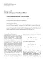
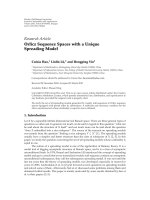
A simple experimental setup, involving KauNet, is shown
in Figure 1. Consider an emulation scenario over a network
with a fixed delay, but where the bandwidth suddenly drops
at a specific instance in time. Assume we want to evaluate the
performance of several IP-based applications in this scenario.
The basic steps to set up the emulation for the setup shown
in Figure 1 would then be as follows. First, the
utility is used to generate a bandwidth pattern. To generate
the bandwidth pattern, the
switch is used together with
the
switch to specify that the positions where the
bandwidth changes occur will be explicitly provided. The
name of the generated bandwidth pattern file is
,
and it is a time-driven pattern covering 1 minute. Assume
that the initial bandwidth is 10 Mbit/s and that there is a
sudden drop in bandwidth to 500 kbit/s after 20 seconds and
that the normal bandwidth is restored after 30 seconds. The
resulting
command thus becomes
The length of the pattern is given in milliseconds.
The position in time of the bandwidth changes and the
bandwidth values themselves are specified as a sequence
of <
>< > pairs. In the example above
the bandwidth pattern is explicitly provided on the com-
mand line. Normally, the pattern would be provided to
as a simple text file. This text file can for
instance be generated by arbitrarily complex models, off-
line simulators, or trace collection equipment. Assuming
the pattern
from
4 EURASIP Journal on Wir eless Communications and Networking
theexampleaboveisputinthefile
an eq uiva-
lent command would be
Next it is time to set up the firewall with on the
KauNet machine. The firewall is first configured to flush out
any old configurations that may be left and to add a default
rule that allows general traffic:
Thenextstepistocreateafirewallrulethatroutesthe
traffic of interest, in this case IP trafficfromHostAtoHost
B, to a pipe where emulation effects are applied.
Thepipemustnowbeconfiguredwiththeemulated
conditions. In this example, the command uses the
keyword to set a static delay of 10 ms. The bandwidth changes
are configured by using the
keyword to load the
bandwidth pattern stored in the
file (which was
generated above).
The emulation scenario is now set up and the impact of
a sudden bandwidth change on various applications can be
evaluated. Although the specified bandwidth change pattern
is only one minute long, the default KauNet behavior is to
wrap around and start using the pattern over again when
the end of the pattern is reached. The configuration above
thus results in a scenario where a sudden bandwidth drop
is experienced for 10 seconds each minute. Note that this is
not intended as a particularly useful or interesting scenario,
but merely serves to illustrate the setup of a simple KauNet
emulation. Further details on KauNet are available in [22].
2.2. Creation of Patterns. The pattern files described in
the previous section are a key element in any emulation
setup. Their content largely decides whether the emulation
is realistic or not, although realism is not the only reason to
create patterns.
Patterns can b e created from a wide spectrum of
tools: they can be written from scratch, generated from an
arbitrarily complex set of models, or distillated from existing
traffic captures, even distillated from the output of a general-
purpose simulator such as ns-2. In a previous work, we
have investigated the coupling of KauNet with an off-line
simulator called SWINE (Simulator for Wireless Network
Emulation) [23]. The input of SWINE is a high-level
experiment description including the involved nodes, their
radio equipment, their mobility model, as well as the general
propagation conditions, the obstacles, and walls. The output
includes a set of KauNet bandwidth and packet loss patterns,
one per pair of nodes. The SWINE simulator engine takes
into account the mobility model of each node to compute
its successive positions, and then the propagation conditions
to compute the successive received signal strength (RSS)
samples using a combination of different radio propagation
models on different scales (e.g., path-loss exponent with log-
normal shadowing, Rice or Rayleigh fading). With the RSS,
a decision is made on which transmission rate is used by the
communicating nodes, and then the effective bandwidth and
packet loss rate to apply at the IP level are computed. The
successive values of bandwidth and packet loss rate are stored
in time-driven patterns that can be applied during the live
emulation stage.
In [24] we demonstrated the use of KauNet with satellite-
specific packet loss patterns, which were produced using the
Markovian Land Mobile Satellite model. A measurement
campaign was led by CNES, the French Space Agency, to
set up parameters values for this Markovian model, which
allowed the generation of carrier-to-noise ratio (C/N)values
for various outdoor environments and land mobile speeds.
These values wer e then processed by a specific IT++-based
simulator that converted them to a packet loss sequence,
emulating a communication stack similar to a DVB-H stack.
When patterns are generated from arbitrarily complex
models or based on previously collected traces, some degree
of realism can be reached. However, the level of realism
reached depends on the quality of the models and the
appropriateness of the parameter values or on the relevance
of the original trace. Generally speaking, realism is not the
only motivation driving the creation of patterns. Patterns
can also be set up to create test situations that rarely
happen in the real world, but under which the user wants
to investigate the reaction of the protocol or application
under test. We have used such “artificial” patterns (as
opposed to “realistic” patterns) during an e valuation of
the TCP stack implementation on FreeBSD 6, which did
not behave as expected when packet losses were inserted at
some specific positions in the real traffic[25]. Such artificial
patterns can serve as unit tests for the validation of protocol
implementations.
2.3. Trigger Patterns. Triggers in KauNet can be seen as
a general information passing functionality that can be
used to deliver precisely positioned control information to
applications or protocols during emulation run-time. As for
other patterns, the trigger patterns can be either data- or
time-driven, according to what is being emulated.
While the trigger mechanism is not tied to any particular
type of control information, it is reasonable to assume
that some types of information will be more prevalent
in emulation scenarios involving opportunistic networking.
One such example is upward flowing cross-layer information
that conveys information on the connectivity of a link.
Triggers allow emulation of cross-layer information in cases
where connectivity is intermittent and the link layer has
the ability to inform upper layers about the presence or
absence of connectivity. This can be combined with other
emulation effects that emulate varying link conditions.
EURASIP Journal on Wireless Communications and Networking 5
Trigge rs
IP traffic
Pipe
Trigger pattern
IP traffic
Host B
KauNet host
Host A
Trigger communication
BW/delay/loss pattern
Adaptation layer
module
Figure 2: KauNet Trigger Overview.
Consider for example a scenario with intermittent connec-
tivity and where the bandwidth available during periods
of connectivity varies heavily. In such a case, bandwidth
patterns can be used to model the bandwidth variations that
occur during connectivity periods. This is then combined
with trigger patterns that generate the upwards flowing
connectivity information that for a real link would come
from the link layer. The bandwidth and trigger patterns are
synchronized with each other to form a consistent emulation
scenario.
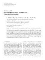
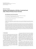
A general view of a simple emulation setup using triggers
is shown in Figure 2. In this setup, two hosts are connected
using a KauNet-enabled host. The KauNet host emulates the
conditions of the particular link or network that is being
emulated by means of bandwidth change, delay change, bit-
error insertion, and/or packet loss patterns, as appropriate.
These patterns control the behavior of the KauNet host
only. The trigger pattern is, just as any pattern, located
at the KauNet host. I n contrast t o other pattern types,
however, triggers are often relevant to other hosts than the
KauNet host. Triggers might, for instance, signal connectivity
information that should be available to a protocol or an
application at Host A. Thus, in addition to trigger patterns, a
trigger communication module and an adaptation layer are
needed to convey and use trigger information accordingly.
KauNet already provides a pattern handling framework
which is reused for encoding the semantics of triggers, thus
simplifying the implementation. The framework provides
the means to create and load compressed pattern files com-
posed of position and value pairs. The values are represented
as short values (i.e., 0–65535) that contain pattern specific
information. For triggers the implication is that no more
than 65536 mutually exclusive trigger values can exist. As
the trigger values that are inserted in a pattern are under the
control of the user, it is possible to generate t riggers leading
to arbitrary complex behavior.
As mentioned, the KauNet pattern framework allows
patterns to be either time-driven or data-driven. In time-
driven mode, the emulation effect of a pattern is applied on
a per millisecond basis. Similarly, with data-driven patterns
emulation effects can b e applied on a per packet basis.
The maximum resolution of a trigger pattern is therefore
one millisecond or one packet. The memory require-
ments of patterns are dependent on the emulation length
and pattern entropy, that is, how often value changes occur in
the patterns. For example, consider a time-driven emulation
setup with 50 individually emulated links, with 3 different
patterns (BW/delay/trigger) per link, and where the values
for each pattern change on average 10 times per second. For
a 30-minute emulation run, the 150 patterns would in total
encompass 10.3 Megabyte.
Triggerpatternsarecreatedinthesamewayasother
patterns. Using the
tool to create a time-driven
trigger pattern that covers 1 minute and inserts trigger values
1, 2, and 3 after 10, 20, and 30 seconds, respectively, would
then result in the following command:
As for other patterns, the trigger pattern may also be
provided to
using a text file.
2.4. Trigger Communication and Interpretation. Since
KauNet is implemented in the FreeBSD kernel, triggers must
be conveyed to external pr ocesses to be useful. Otherwise,
only kernel space processes running locally on the KauNet
hostwouldbeabletobenefitfromthetriggerfunctionality.
Thus, a mechanism to transfer the trigger value of a fired
trigger to an arbitrary receiver is needed. The recipient of a
trigger should be able to reside in either user space or kernel
space, locally or on another host.
This functionality is implemented by the trigger com-
munication module s hown in Figure 2. This module has
a number of responsibilities. First, to enable both local
and nonlocal communications the module provides a UDP
interface. Using this interface, adaptation layers can register
themselves to receive triggers from a certain pipe. The trigger
communication module keeps a list of all registered adapta-
tion layers to enable multiple adaptation layers to subscribe
to the same trigger. Second, whenever a trigger is fired within
KauNet, the module transmits the trigger information to the
registered adaptation layers. The communication of triggers
is also done using UDP. Finally, the trigger communication
module also provides the means for adaptation layers to
unregister themselves.
To ensure that there is no possibility for trigger control
traffic and experimental traffic to interfere with each other,
6 EURASIP Journal on Wir eless Communications and Networking
trigger traffic should be separated by using a separate
control network with separate network interfaces. The low
bandwidth consumed by trigger control trafficensuresthat
the UDP control packets are very unlikely to be lost due
to buffering or congestion in the contr ol network. The
bandwidth requirements for trigger traffic can be exemplified
by the requirements of the 50-link scenario described in
the previous subsection, and where triggers are used to
signal bandwidth changes that in a real en vironment w ould
be propagated by an intelligent link layer. Counting all
header overhead, the bandwidth requirements for that 50-
link scenario is only 312 kbps, that is, less than 0.03% of
the capacity of a gigabit Ethernet control network. From
a scalability viewpoint, control traffic bandwidth is thus
unlikely to become a concern. Even if the trigger control
traffic is scaled up to the point where UDP losses might
occur, it can be noted that the effectofatriggerpacketlossis
localized both in space and time. Thus, it will cause a missed
update for one single link and only for the time period until
the subsequent trigger is received. It is also possible to employ
multiple KauNet nodes to perform emulation and send out
triggers. Depending on the use-case, this may, however, also
require the added complexity of synchronization between
multiple KauNet hosts, and such synchronization has not
been tested yet.
In addition to the UDP-based trigger communication
discussed here, it is also possible to employ other methods
for trigger communication. In [26], alternatives for trigger
communication were examined with a tilt towards commu-
nication methods that allow triggers to be communicated
locally from the kernel to local user-space processes. In
addition to UDP traffic, which uses AF
INET sockets,
examined approaches were signals with different shared
memory setups, and AF
UNIX IPC sockets. While signal-
based approaches were found to have higher throughput
than external AF
INET sockets, internal AF UNIX sockets in
some cases had worse performance than external AF
INET
UDP traffic. Although slightly less efficient t han signal-
based approaches, the performance of external AF
INET
UDP traffic well surpassed the expected requirements for
trigger communication. As UDP-based trigger communica-
tion was considered to be the most flexible of the evaluated
approaches, it was chosen for the implementation.
The interpretation of triggers is handled by different
adaptation layers. In general, an adaptation layer is a process,
or part of a process, that is able to interface with the trigger
communication module and thereby receive triggers. In the
context of opportunistic networking, trigger values are likely
to represent some sor t of cross-layer information. The role
of the adaptation layer is then to work as an interface
between the trigger communication module and the upper
layer consumer of cros-layer information. Applications and
protocol implementations may use cross-layer information
in different ways and the information may take different
formats. It is the role of the adaptation layer to reshape the
semantics-free trigger values contained in the triggers into
the specific type of cross-layer information that is used by
the application or protocol that is being evaluated. In the
next section, we describe an adaptation layer for the DTN2
reference implementation [27], which interprets the trigger
values (1 or 2) as connectivit y information (link up or down)
and interfaces with the link discovery mechanism within the
DTN2 implementation.
3. A DTN Adaptation Layer
This section describes how to implement and use an
adaptation layer for DTNs where the experimentation nodes
run the Bundle Protocol [28], in this case the DTN2 reference
implementation [ 15, 27]. One of the most distinctive
features of DTNs is the intermittent connectivity between
nodes. Over time, contact opportunities arise and allow the
forwarding of data bundles towards their final destination.
Those o pportunities are mainly characterized by a time
window and the contactable peer ID (EID). Opportunities
may be predictable or not, according to the considered
application. In some cases, several links allow for the contact
between two peers, in which case there are several contact
opportunities, one per availablelinkforthecontact.Each
node running the DTN2 implementation has a component
that manages contact opportunities, as well as optional
components providing contact discovery.
The adaptation layer implementation described here
mainly consists in using triggers to emulate contact opportu-
nities. It implies the development of a new Discovery mecha-
nism in the DTN2 reference implementation. On each DTN2
node, the new discovery mechanism is in charge of detecting
contact opportunities by connecting to the KauNet trigger
communication module and extracting contact information
from the trigger values, thus constituting the trigger adap-
tation layer. Bundle forwarding is unchanged and carried
out o ver Ethernet on the experimental network according
to the announced opportunities and the local DTN2 node
configuration. Regardless if the contact opportunities are
predictable or not at higher layers, hooking into the DTN2
implementation via a custom Discovery adaptation layer
allows the emulation of many different flavors of D TNs; the
only difference lies in the creation of the contact triggers.
The implementation of the custom Discovery mechanism is
further described below.
3.1. Implementation. In the DTN2 reference implementa-
tion, an IP Discovery/Announce mechanism is provided
for detecting and creating opportunistic links in IP-based
networks. A convergence layer ma y announce its presence
by sending out beacons with regular intervals, either as a
broadcast message across the entire network or as a unicast
for specific nodes. The IP Discovery mechanism listens for
these beacons. When an announce packet is detected, the
contained information is extracted and a new opportunistic
link is created using the IP address, port and EID of the
remote node, as well as the type of the convergence layer that
is broadcasting.
In order for KauNet to control the opening and closing
of opportunistic links in DTN2, a new KauNet Discov-
ery/Announce mechanism is implemented. The discovery
mechanism is implemented as a new Discovery subclass.
EURASIP Journal on Wireless Communications and Networking 7
Similarly to the IP Discovery mechanism, it listens for
custom KauNet triggers (that act similarly to beacons) on a
specific port. It provides functionality for the DTN2 node to
register (and unregister) itself at a KauNet host, in order to
receive the contact triggers that describe the status of a link.
Note that the KauNet triggers are received over the control
network and not over the interface whose connectivity
they control. The KauNet Discovery mechanism parses the
triggers it receives and opens a link (creating it if necessary)
or closes a link, depending on the received trigger value: 1
means “open” and 2 means “close”.
The announce mechanism is not implemented within the
DTN2 adaptation layer. Instead, it is provided by the KauNet
trigger communication module. The trigger communication
module simply stores the DTN2 clients registered for each
pipe and sends out KauNet triggers to subscribing clients
whenever a trigger event takes place in a pipe.
KauNet does not handle the link discovery information
used by DTN2 (specifically, the t ype of convergence layer,
the IP address used to communicate with it, and the EID
of the DTN2 node on which the convergence layer resides).
The KauNet triggers contain no link information other than
the status ( i.e., open or closed). Therefore, the discovery
mechanism requires alternative means in order to obtain
the required link information. This information is instead
provided in the configuration file of each DTN2 node
that uses KauNet controlled links (see Section 3.2). The
configuration file also contains the information required to
send a subscription request to the KauNet host controlling
the links. Note that an alternative implementation would
have been to include the link discovery information in the
KauNet triggers. This alternative was rejected, as it was
considered more consistent with the DTN2 configuration
to include the link information as part of the configuration
for KauNet Discovery instances at each node. The chosen
solution also allows the connectivity trigger patterns to be
easily reused in different communication scenarios.
3.2. Usage. As in the original DTN2 implementation, oppor-
tunistic links are detected using a discovery mechanism. A
node must add one entry to its configuration file for each
opportunistic link it needs to discover. The entry contains
the required link and subscription information and has the
following syntax:
< >
< > < >
< > < > < >
< > < >
The parameters of the discovery entry are detailed below.
<
>
The name of this discovery instance, used for identi-
fication by DTN2.
< >
The IP address of the KauNet host that emulates the
connectivity of this link.
< >
(Optional) The port used by the KauNet host to listen
for subscription requests. If no value is specified, the
default KauNet p ort (1066) is used.
< >
The ID number of the pipe used to emulate the link
at the KauNet host.
< >
The IP address of the convergence layer on the DTN2
node that this link repres ents a connection to.
< >
(Optional) The port of the convergence layer on the
DTN2 node this link r epresents a connection to. If no
value is specified, the default TCP/UDP convergence
layer port (4556) is used.
< >
The type of convergence layer used on the DTN2
node this link represents a connection to.
< >
The EID of the DTN2 node this link represents a
connection to.
(Optional) A flag indicating that the link should be
initialized as an open and available link. If this flag is
not set, the link must first be opened with a KauNet
trigger before DTN2 can use it to send data.
As DTN2 is loaded, the
,
and custom arguments are used to generate and
send a single subscription request to the KauNet host at
initialization. It is therefore important to load the trigger
communication module on the KauNet host before starting
any DTN2 node, or the subscription requests will fail.
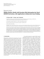
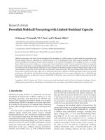
An example setup is shown in Figure 3.Itfeaturesa
control network (192.168.1/24) for non-experiment traffic
and two experiment networks (10.0.1/24 and 10.0.2/24). It
features two DTN2 nodes, A and B, and a node running
KauNet that is used to control the availability and properties
of the link between DTN2 nodes A and B. As DTN links
may provide asymmetric data rates, two pipes are used to
model the link between node A and B. In our example,
node A runs the KauNet discovery mechanism to keep track
of the c onnectivity of the link between node A and node
B. It receives triggers over the control network from the
KauNet machine. When a trigger is received indicating that
the link is available, node A establishes a connection to a TCP
convergence layer on host B. The discovery part of the DTN2
configuration file at node A has the following entry:
8 EURASIP Journal on Wir eless Communications and Networking
Triggers
192.168.1.1
Pipe 1
delay, BW, trigger
Pipe 2
delay, BW
KauNet
dtn://B.dtn
Host B : 10.0.2.1Host A: 10.0.1.1
dtn://A.dtn
tcpBdiscB
Figure 3: Emulation setup.
Node A registers at the KauNet host (192.168.1.1) via the
control network on the default port. It subscribes to
,
which is the pipe configured with the connectivity pattern for
the link between nodes A and B. When the discovery instance
is loaded, the subscription request will be automatically
sent using the information from the configuration file. The
details of the remote convergence layer are also given by the
configuration.
As the discovery is made through the KauNet triggers
there is no need to run an Announce mechanism on node B.
Node B only has to define an interface that creates a standard
TCP convergence layer. In our example, the default TCP
convergence layer port is used. The corresponding interface
command in the DTN2 configuration file at node B is
When a connectivity opportunit y appears and a connec-
tion over TCP has been established, the established DTN link
will be available for bidirectional communication, in other
words implicitly discovered by node B. There is therefore no
need to run a discovery mechanism on node B. Note that
the same behavior is not true for the UDP convergence layer
which requires each node to discover its own uplink.
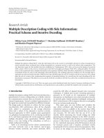
4. The Village Example
This section describes an emulation scenario typical of a
delay-tolerant network. It is a data mule setup where a bus
is used as a mechanical backhaul intermittently connecting
villages to the Internet. This Village example is inspired
by the DakNet [20]andKioskNet[21]projectsandis
illustrated by Figure 4. In this section, however, we simplify
the architecture to keep the example tractable. Three DTN
nodes are considered: a kiosk, which is typically in an isolated
village, used by the inhabitants for intermittent access to the
Internet; a bus that p eriodically comes to the village; and
a gateway in the city that is permanently connected to the
Internet. When a villager sends a mail, a bundle is created
and waits at the kiosk until the bus arrives. The bundle is then
forwardedtothebusnodeandtravelswiththebusuntilthe
next arrival of the bus to the gateway in the city. The bundle
is then forwarded to the gateway, which can retrieve the mail
and send it the usual way.
Internet region
Cily
Bus
Village region
Figure 4:TheVillageExample(from[15]).
Under these conditions, the distribution of opportunistic
contacts over time is as follows in a periodic way: no contact,
kiosk/bus contact, no contact, gateway/bus contact, and so
forth. In a real setup, contacts may be several hours apart and
would not follow a strict period. In our tests, we have scaled
down the duration of a complete bus trip to a few minutes,
and made it strictly periodic, to improve the readability of
the obtained results. However, this is not a limitation of
the KauNet tools, and much more random contacts can be
implemented.
4.1. Trigger and Bandwidth Patterns Used. In this setup,
two ty pes of time-driven patterns are used to model what
happens during opportunistic contacts: trigger patterns
model contact opportunities, and bandwidth patterns model
the bandwidth available over the link at the IP level.
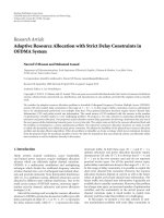
First, due to the mobility of the bus, the quality of the
link with the encountered kiosk or gateway varies during the
contact. The connection is made with TCP over WiFi. Several
papers [29, 30] show that the TCP goodput as well as the
MAC bit rate has a specific shape, which follows a three phase
model, for drive through connections. We have simplified
this to a trapezoid for modeling the bandwidth of both
the kiosk/bus and the gateway/bus contacts. Figure 5 shows
both shapes and when they take place in one full period. To
implement both shapes, we first generate bandwidth shape
values for both links with a granularity of 100 ms to files
and with a simple py thon script. We then
generate time-driven bandwidth patterns
and
with the command:
Although the period of 6 minutes used is quite unrealis-
tic, the duration of a contact of approximately one minute
as well as the maximum goodput of 22 Mb/s matches the
observations made in the above cited papers, for a bus
traveling at 80 km/h and a gateway next to the road.
Second, trigger patterns emulate contact discovery with
the mechanism described in Section 3, involving the trigger
adaptation layer added to the DTN2 reference implementa-
tion. One pattern is needed for each pair of opportunistically
EURASIP Journal on Wireless Communications and Networking 9
0
5
10
15
20
25
Kiosk-bus bandwidth
Bus-gateway bandwidth
Bandwidth (Mbps)
Time (seconds)
0 50 100 150 200 250 300 350
Figure 5: Bandwidth patterns.
connected nodes: one pattern for kiosk/bus contacts and
one for bus/gateway contacts. The trigger pattern is a time-
driven pattern w ith a very simple semantic: a trigger value
of 1 means “enable contact” and a trigger value of 2 means
“disable contact”. These patterns are also defined manually
using the
command. We have considered different
sensitivities: high sensitivity means that the contact is
discov ered as soon as some signal is available, that is, at
the beginning of the bandwidth ramp; low sensitivity means
that the contact is discovered only when the maximum
bandwidth is available, that is, when the top of the band-
width ramp is reached; medium sensitivity lies in-between.
Sensitivities and how they relate to the bandwidth ramp are
illustrated in Figure 6.
For instance, the high sensitivity trigger patterns for both
links are generated as follow:
Note that both trigger and bandwidth patterns can be
generated based on a mobility model or on the output of
a simulator, thus introducing potentially more randomness
and/or c crealism.
The ability to couple the contact opportunity trigger
pattern with another type of pattern using KauNet’s time-
driven mode is a very convenient feature that can be
used in various other scenarios. For example, in a DTN
space scenario such as the one described in [18], contact
opportunities correspond to the low earth orbit satellite UK-
DMC passing above a ground-station, for a duration of 5
to 14 minutes. During each pass, delay and throughput are
constant while the bit error rate varies a lot (high BER at the
start and the end of the pass, when the satellite elevation is
low). This can be emulated with a bit-errors insertion pattern
coupled with a high-sensitivity contact trigger pattern.
0
5
10
15
20
25
30
35
High sensitivity contact
Medium sens.
Low sens.
Bandwidth
Bandwidth (Mbps)
Time (seconds)
40 60 80 100 120 140
Figure 6: Trigger patterns: three different sensitivities.
dtn://K.dtn
Kiosk:10.0.1.1
Pipe 2
delay, BW
Pipe 1
delay, BW, trigger
Pipe 101
delay, BW, trigger
Pipe 102
delay, BW
KauNet
dtn://GW.dtn
Gateway:10.0.1.3
dtn://B.dtn
Bus:10.0.2.1
discBus
discBus
tcpBus
Figure 7: KauNet Setup for the Village Example.
4.2. Infrastructure Deployment on KauNet. We choose to
deploy the Village Example on a 4-host setup, with one
host per DTN node (kiosk, bus, and gateway) plus the
KauNet host. The DTN hosts are Linux hosts (Ubuntu 9.10)
with the DTN2 reference implementation as well as the
KauNet adaptation layer previously described. As illustrated
by Figure 7, the kiosk (K) is mapped to host A (10.0.1.1), the
bus (B) is mapped to host B (10.0.2.1), and the gateway (GW)
is mapped to host C (10.0.1.3). The fourth host is the KauNet
box. Having the kiosk and the GW on one subnet and the
bus on another is a convenient deployment for setting up
the routing to ensure that all data transmissions go through
KauNet.
KauNet is configured with two unidirectional pipes per
link. The kiosk to bus pipe has number 1 and the reverse
bus to kiosk has number 2. The bus to gateway link has
number 101, and the reverse gateway to bus pipe has number
102. The same bandwidth pattern
is applied on both
directions of the kiosk/bus link, that is, pipes 1 and 2. The
contacts trigger pattern
is loaded only on pipe 1,
10 EURASIP Journal on Wireless Communications and Networking
0
200
400
600
800
1000
1200
0 6 12 18 24 30 36 42 48 54 60
Delivered packets
Time (min)
Low sensitivity
Medium sensitivit y
High sensitivity
dtnsend/recv performance
Figure 8: Bundle delivery over time.
but once the DTN2 TCP convergence layer discovers a con-
tact on the forward direction, it automatically “discovers” the
contact also on the reverse direction. Similarly, a bandwidth
pattern
is shared on pipes 101 and 102, while the
contact pattern
for bus and gateway is loaded only
on pipe 101:
4.3. DTN2 Configuration. For each of the mapped entities
(K, GW, and B), a TCP convergence layer or a KauNet
discovery mechanism is added to the DTN2 configuration of
its host. The bus has a simple convergence layer statement,
while the kiosk and gateway have discovery statements
that refer to B’s convergence layer. Below is the DTN2
configuration of the bus:
Table 1: Bundles delivered per round.
Sensitivity Average 95% c.i.
High 110.3 1.0
Medium 95.3 2.4
Low 66.5 1.8
The DTN2 configuration of the kiosk, shown below, has
a discovery statement referring to the interface declared in
the bus configuration above. It also refers to the KauNet host
and to pipe 1, on which the kiosk/bus contact trigger pattern
was loaded:
Below is the configuration of the gateway. Also this
discovery statement refers to the interface declared in the bus
configuration above, as well as to pipe 101, on which the
bus/gateway contact trigger pattern
was loaded:
4.4. Applications Deployment. Now that the infrastructure is
deployed and the throughput and contact patterns have been
defined, the platform is ready for application-level testing.
Among all possible tests, we report on a simple data delivery
test, evaluating how the sensitivity of the contact patterns
impacts bundle delivery.
The applications used are the dtnsend and dtnrecv com-
mands packaged with the DTN2 reference implementation.
The sender is hosted by the kiosk (K) and the receiver is
hosted by the gateway (GW). The sender application sends
5000 bundles of 1 MByte, which are then slowly forwarded
to the b us, the gateway, and finally the receiver application as
contact opportunities arise. We measure how many bundles
are delivered to the gateway for every bus round-trip, over
30 rounds. Figure 8 shows the evolution of the amount of
delivered bundles during the 10 first bus rounds for high,
medium, and low sensitivities. Over 30 bus rounds, we obtain
the results in Table 1 .
The steps observed in Figure 8 closely match the no-
contact periods between the bus and the gateway, that
is,thereceiver.Onecanalsoseethatthefirstbundles
are delivered at the receiver application after 3 minutes,
that is, at the beginning of the first bus/gateway contact
EURASIP Journal on Wireless Communications and Networking 11
0
10
20
30
40
50
60
70
80
90
100
180 185 190 195 200 205 210 215 220 225 230
Delivered packets
Time (seconds)
Low sensitivity
Medium sensitivit y
High sensitivity
dtnsend/recv performance
Figure 9: Bundle delivery over time (magnified).
and one minute after the end of the first kiosk/bus contact.
Another observation that can be made is that the proportion
of contact time lengths is not matched by the proportion
of packet delivery steps: although a high-sensitivity contact
lasts twice as long as a low-sensitivity one, there are not
twice as many bundles delivered. This is due to the effect
of the bandwidth ramp shown in Figure 6:theextratime
of the high-sensitivity contact corr esponds to the beginning
and ending ramps where less data can be forwarded. Finally,
in Figure 9 a magnified view of the first step shows that
for the medium-sensitivity, case bundle delivery occurs a
few seconds after the high-sensitivity curve, and a few
seconds later for the low-sensitivity case. These times are
related to t he 7.5-second offsets in the sensitivity timings of
Figure 6. The exponential shape of the beginning of the high-
sensitivity packet-delivery curve is due to the increase of the
bandwidth over time, which leads to a decrease of delivery
delays for the bundles. This shape can also be observed to
a smaller extent in the medium-sensitivity cur ve. It is not
present in the low-sensitivity case because in that case the
bandwidth is constant during the whole contact time.
4.5. Multiple Kiosk Scenario. The emulated example
described above is limited to three DTN nodes to keep the
description simple. The emulation capabilities of KauNet
in general and of the trigger mechanism in particular,
is however easily scalable to scenarios involving a larger
number of nodes. As a single KauNet node can emulate
multiple links, the emulated scenario can be scaled up
with more DTN nodes by adding pipes to the KauNet
configuration. The number of links (i.e., pipes) that can
be supported is mainly dependent on the amount of
simultaneous traffic generated over the emulated links and
on the capacity of the experimental network.
0
5
10
15
20
25
0 2 4 6 8 10 12 14 16 18 20 22 24 26
Bandwidth (kbps)
Time (min)
K1-bus
K2-bus
K3-bus
K4-bus
K5-bus
K6-bus
K7-bus
K8-bus
K9-bus
K10-bus
K11-bus
K12-bus
Bus-GW
Figure 10: Bandwidth patterns for multiple kiosk scenario.
To verify the trigger mechanism in a slightly larger
setup, we have extended the basic village scenario, discussed
previously, to a scenario where the bus passes through 12
different villages (with one kiosk in each village) during a
round-trip. The bandwidth patterns used for the multiple
kiosk scenario are illustrated in Figure 10,showingone
complete bus round-trip. As in our previous example, we use
a fully periodic schedule and have compressed the contact
opportunities in time. As seen in the figure, the bus makes
contact with one of the kiosks or with the gateway every other
minute, which allows one round-trip to be completed in 26
minutes. As before, each contact lasts for one minute and
follows a three-phase trapezoidal model.
The extended scenario inv olves a total of 14 DTN nodes.
To limit the number of physical machines required, in
this setup we deploy t he kiosk nodes and the GW node
using virtualization. One of our experimental machines runs
VMware ESXi [31] and we deploy 13 virtual machines on the
VMware host. One DTN node is run in each virtual machine.
Note that the scalability and deployment of the DTN nodes is
a separate issue from the scalability of the KauNet emulation
itself.
The setup of the multiple kiosk scenario is illustrated
in Figure 11. As before, two pipes are used to emulate each
DTN link resulting in a total of 26 pipes. The configuration
of the scenario is done in the same way as for the 4-
node case detailed earlier. A bandwidth pattern and trigger
pattern is created for each link. As described in Section 4.2,
the bandwidth pattern is applied in both directions of a
link whereas the trigger pattern only needs to be loaded
for one direction. The trigger patterns are based on the
medium sensitivity pattern explained in Section 4.2.The
configuration of the D TN nodes follows the configuration
described in Section 4.3. Each kiosk node and the GW
node have a KauNet discovery mechanism configured.
12 EURASIP Journal on Wireless Communications and Networking
dtn://K1.dtn
dtn://K12.dtn
dtn://GW.dtn
KauNet
Pipe 26
delay, BW
Pipe 25
delay, BW, trigger
Pipe 24
delay, BW
Pipe 23
delay, BW, trigger
Pipe 2
delay, BW
Pipe 1
delay, BW, trigger
dtn://B.dtn
discBus
discBus
discBus
tcpBus
···
···
VMware host
Figure 11: KauNet setup for the multiple kiosk example.
The only difference between the discovery statements of these
nodes is that they register to different KauNet pipes to receive
the correct connectivity information for their respective link
to the bus. The configuration for the bus node is unchanged.
For the multiple kiosk scenario, we choose to evaluate
the impact on bundle delivery performance of the number of
kiosks that need to communicate via the gateway. As before,
dtnsend and dtnrecv are used for the communication, with
senders hosted at the kiosks and the receiver hosted at the
gateway. When active, the sender application at a kiosk sends
1000 bundles of 1 MByte. We evaluate the bundle delivery
performance of Kiosk 1 with varying number of sending
kiosks. Four configurations are compared: only Kiosk 1 is
sending, 4 kiosks (Kiosks 1, 4, 7, and 10) are sending, 8
kiosks(Kiosks1,3,4,6,7,9,10,and12)aresending,and
all 12 kiosks are sending. Figure 12 shows the evolution of
the amount of delivered bundles from Kiosk 1 during the 20
first bus rounds.
The impact of the number of sending kiosks is clearly
displayed in Figure 12. When Kiosk 1 is the only kiosk with
bundles to send, a regular number of bundles is delivered
each round. Less than 20 rounds are needed to deliver all the
1000 bundles. When multiple kiosks have bundles to send,
on the other hand, bundles from Kiosk 1 are only delivered
to the gateway in some of the rounds, and only a fraction
of the 1000 Kiosk 1 bundles are delivered during the first
20 rounds. The link between the b us and the gateway is
shared by all kiosks on their paths from sender to receiver
and becomes a bottleneck. It can be seen that the DTN2
reference implementation of the bundle layer uses FIFO
queuing. Kiosk 1 is the first kiosk passed by the bus during a
bus round, and the Kiosk 1 bundles picked up during the first
round are the first to be delivered to the gateway. The Kiosk 1
bundles picked up during the second round are queued
behind bundles from other kiosks picked up during the first
round. They cannot be delivered until all bundles from the
first round have been delivered. As can be seen in the figure,
0
100
200
300
400
500
600
700
800
900
1000
0 60 120 180 240 300 360 420 480
Delivered packets
Time (min)
1 kiosk sending
4 kiosks sending
8 kiosks sending
12 kiosks sending
dtnsend/recv performance
Figure 12: Bundle delivery of Kiosk 1 over time.
the queuing delay encountered by the Kiosk 1 bundles is
directly dependent on the number of kiosks competing for
the bottleneck link. The exact number of bundles delivered
from a kiosk to the bus or from the bus to the gateway varies
slightly between contacts. As a consequence, the Kiosk 1
bundles received by the bus in a given round are typically
delivered to the gateway during more than one round once
they reach the head of the queue.
The multiple kiosk scenario aims to illustrate the use
of KauNet triggers in a slightly larger setup where several
DTN senders interact. It also illustrates the importance of the
placement of the gateway. In our example, bundle delivery
delay increases roughly proportionally with the number of
sending kiosks. A simple solution to reduce the delay in
bundle delivery would of course be to allow the bus and
gateway a longer contact time, thus reducing the impact of
the bottleneck link. Depending on the scenario, it may also
be interesting to consider different queuing disciplines at the
bundle layer.
5. Conclusions
By extending the pattern-based KauNet emulation system
with pattern-driven triggers, it is possible to emulate oppor-
tunistic communication scenarios that depend on cross-
layer information. The triggers can be tightly controlled and
accurately synchronized with other emulation effects. The
triggers are distributed to local and remote processes by the
trigger communication module, where the adaptation layer
is responsible for translating the triggers into application-
specific semantics and actions. An adaptation layer for DTNs
was described and its use in emulating a simple DTN
scenario was detailed. The DTN examples serve to highlight
the functionality and applicability of the trigger mechanism.
Adequate emulation support allows effective debugging,
accurate and reproducible performance evaluations, and user
studies of protocols and applications. It is our hope that
EURASIP Journal on Wireless Communications and Networking 13
the proposed triggers will allow researchers in opportunistic
networks to perform all these tasks in a more cost- and
time-efficient way, and thereby contribute to the further
advancement of the field.
Possible future work includes emulating a realistic end-
to-end space scenario where data must be collected in
remote field areas through a Low Earth Orbit satellite.
Such a scenario would interconnect mixed technologies:
outdoors wireless sensor network, an Earth-satellite link and
the Internet, also including specific protocols like Saratoga
or LTP as convergence layers. Emulation would b e used
to generate Earth/satellite contacts, including bit-error rate
evolution during a contact. The purpose of the setup would
be to assess different infrastructure deployments with respect
to maximum delivery time.
The emulation setups presented in this p aper are well
suited for experiments involving a few dozens physically
interconnected DTN nodes. However, emulating oppor-
tunistic networks involving hundreds of nodes is not pos-
sible. For future work, we intend to explore to what extent
a majority of such emulated nodes can be abstracted away,
leaving a physical emulation setup involving only a few
end nodes. We are currently investigating approaches to
abstracting down a DTN network to only a few nodes while
retaining the characteristic behavior.
Acknowledgments
The authors wish to thank Andreas Midestad for his work
on the implementation of triggers. This work was partly
supported by the European Commission in the framework of
the FP7 Network of Excellence in Wireless COMmunications
NEWCOM++ (contract no. 216715).
References
[1] K. Fall, “A delay-tolerant network architecture for challenged
internets,” in Proceedings of the Annual conference of the Special
Interest Group on Data Communication (SIGCOMM ’03),
vol. 33, no. 4, pp. 27–34, August 2003.
[2] V.Cerf,S.Burleigh,A.Hookeetal.,“Delay-tolerantnetwork-
ing architecture,” Tech. Rep. RFC 4838 (Informational), April
2007.
[3] L. Lilien, Z. H. Kamal, and A. Gupta, “Opportunistic networks
for emergency applications and their standard implementa-
tion framework,” in Proceedings of the 17th International Con-
ference on Database and Expert Systems Applications (DEXA
’06), September 2006.
[4] D. Raychaudhuri, I. Seskar, M. Ott et al., “Overview of the
ORBIT radio grid testbed for evaluation of next-generation
wireless network protocols,” in Proceedings of the IEEE Wireless
Communications and Networking Conference (WCNC ’05),pp.
1664–1669, New Orleans, La, USA, March 2005.
[5]J.Flynn,H.Tewari,andD.O’Mahony,“JEmu:arealtime
emulation system for mobile Ad Hoc networks,” in Proceedings
of the 1st Joint IEI/IEE Symposium on Telecommunications
Systems Research, Dublin, Ireland, November 2001.
[6]P.ZhengandL.M.Ni.,“EMWin:emulatingamobile
wireless network using a wired network,” in Proceedings
of the 5th ACM international workshop on Wireless mobile
multimedia (WoWMoM ’02), pp. 64–71, ACM, Atlanta, GA,
USA, September 2002.
[7] L. Rizzo, “Dummynet: a simple approach to the evaluation of
network protocols,” Computer Communication Review, vol. 27,
no. 1, pp. 31–41, 1997.
[8] S. Hemminger, “Network emulation with NetEm,” in Pro-
ceedings of the Linux Australia Conference, Canberra, Autralia,
April 2005.
[9] A. Vahdat, K. Yocum, K. Walsh et al., “Scalability and accu-
racy in a large-scale network emulator,” SIGOPS—Operating
Systems Review, vol. 36, supplement 1, pp. 271–284, 2002.
[10] M. Carson and D. Santay, “NIST net—a linux-based network
emulation tool,” ACM SIGCOMM Computer Communication
Review, vol. 33, no. 3, pp. 111–126, 2003.
[11] B. White, J. Lepreau, and L. Stoller, “An integrated experi-
mental environment for distributed systems and networks,” in
Proceedings of 5th Symposium on Operating Systems Design and
Implementation (OSDI ’02), pp. 255–270, ACM Press, Boston,
Mass, USA, December 2002.
[12] B. D. Noble, M. Satyanarayanan, G. T. Nguyen, and R. H. Katz,
“Trace-based mobile network emulation,” ACM SIGCOMM
Computer Communication Review, vol. 27, no. 4, pp. 51–61,
1997.
[13] S Y. Wang and Y B. Lin, “NCTUns network simulation
and emulation for wireless resource management,” Wireless
Communications and Mobile Computing, vol. 5, no. 8, pp. 899–
916, 2005.
[14] G. Xylomenos and B. Cici, “Design and evaluation of a socket
emulator for publish/subscribe networks,” in Proceedings of the
Future Internet Symposium, Berlin, Germany, September 2010.
[15] M.Demmer,E.Brewer,K.Fall,S.Jain,M.Ho,andR.Patra,
“Implementing delay tolerant networking,” Tech. Rep. IRB-
TR-04-020, Intel Research, December 2004.
[16] NASA Glenn Research Center, “Channel Emulator Resources,”
http://channel-emulator.g rc.nasa.gov/ .
[17] R. Slywczak, “Development of network-based communica-
tions arc hit e ctures for future NASA missions,” in Proceed-
ings of the of the Interservice/Industry Training, Simulation,
and Education Conference (I/ITSEC ’07),Orange,Fla,USA,
November 2007.
[18] W. Ivancic, W. M. Eddy, D. Stewart et al., “Experience with
delay-tolerant networking from orbit,” in Proceedings of the 4th
Advanced Satellite Mobile Systems (ASMS ’08), pp. 173–178,
Bologna, Italy, August 2008.
[19] P. Hurtig, T. P
´
erennou, J. Garcia, and A. Brunstrom, “Using
triggers for emulation of opportunistic networking,” in
Proceedings of the 2nd International Workshop on Mobile
Opportunistic Networking (MobiOpp ’10), pp. 155–158, Pisa,
Italy, February 2010.
[20] A. Pentland, R. Fletcher, and A. Hasson, “DakNet: rethinking
connectivity in developing nations,”
Computer, vol. 37, no. 1,
pp. 78–83, 2004.
[21] A.Seth,D.Kroeker,M.Zaharia,S.Guo,andS.Keshav,“Low-
cost communication for rural internet kiosks using mechan-
ical backhaul,” in Proceedings of the Annual International
Conference on Mobile Computing and Networking (MOBICOM
’06), pp. 334–345, Los Angeles, Calif, USA, 2006.
[22]J.Garcia,E.Conchon,T.P
´
erennou, and A. Brunstrom,
“KauNet: improving reproducibility for wireless and mobile
research,” in P roceedings of the 5th International Conference
on Mobile Systems, Applications and Services (MobiEval ’07),
pp. 21–26, San Juan, Puerto Rico, June 2007.
14 EURASIP Journal on Wireless Communications and Networking
[23] E. Conchon, T. P
´
erennou, J. Garcia, and M. Diaz, “W-
NINE: a two-stage emulation platform for mobile and w ireless
systems,” EURASIP Journal on Wireless Communications and
Networking, vol. 2010, Article ID 149075, 20 pages, 2010.
[24] T. P
´
erennou, A. Bouabdallah, A. Brunstrom, J. Gar cia, and
P. Hurtig, “IP-level satellite link emulation with KauNet,”
in Proceedings of the International Workshop on Satellite and
Space Communications (IWSSC ’09), pp. 349–353, Siena, Italy,
September 2009.
[25] P. Hurtig, J. Garcia, and A. Brunstrom, “Loss recovery in
short TCP/SCTP flows,” Karlstad University Studies 2006:71,
Karlstad University, Karlstad, Sweden, December 2006.
[26] T. Hall and A. Midestad, Kaunet triggers, M.S. thesis, Karlstad
University, Faculty of Economic Sciences, Communication
and IT, Karlstad, Sweden, 2010.
[27] Delay Tolerant Networking Researc h Group, DTN Reference
Implementation, .
[28] K. Scott and S. Burleigh, “Bundle protocol specification,” Tech.
Rep. RFC 5050, Internet Engineering Task Force, November
2007.
[29] D. Hadaller, S. Keshav, T. Brecht, and S. Agarwal, “Vehicular
opportunistic communication under the microscope,” in
Proceedings of the 5th International Conference on Mobile
Systems, Applications and Services (MobiSys ’07), pp. 206–219,
San Juan, Puerto Rico, June 2007.
[30] J. Ott and D. Kutscher, “A disconnection-tolerant transport
for drive-thru internet environments,” in Proceedings of the
24th Annual Joint Conference of the IEEE Computer and
Communications Societies (INFOCOM ’05), vol. 3, pp. 1849–
1862, Miami, Fla, USA, 2005.
[31] VMware Inc., “VMware ESXi Product Information,” http://
www.vmware.com/products/esxi/.