Programmable Logic Controller plant through MMI Part 11 potx
Bạn đang xem bản rút gọn của tài liệu. Xem và tải ngay bản đầy đủ của tài liệu tại đây (514.52 KB, 13 trang )
New Applications Using PLCs in Access Networks
123
band. Next is the noise that appears on the other pair but at the same end of the cable as the
source of interference (Cook et al., 1999), as shown in Fig. 1.
Fig. 1. Illustration of Next
Fext is the noise that appears on another pair, but at the opposite or far end of the cable to
the source of noise (Cook et al., 1999). Fext is less harmful than Next since it is mitigated
because the distance between the source and the noise receiver. Fig. 2 is an example of Fext.
Fig. 2. Illustration of Fext
Techniques such as DSM (dynamic spectrum management) and MIMO (multiple-input
multiple-output) schemes try to find a controlled injection of spectrum in DSL systems so
that the resulting crosstalk can assume acceptable performance values (Starr et al., 2003),
(Ödling et al., 2009).
2.2 Wireless Broadband Networks (WBN)
A large number of wireless technologies exist and other systems still being under design.
These technologies can be distributed over different network families, based on a system
scale (Nuaymi, 2007):
• A wireless personal area network (WPAN) is a data network used for communication
among data devices close to one person;
• A wireless local area network (WLAN) is a data network used for communication
among data devices: computer, telephones, printer and personal digital assistants
(PDAs). This network covers a relatively small area, like a home, an office or a small
campus (or part of a campus);
Pair 1
Pair 2
Crosstalk
transmitter
Far-End
Receiver
Cable
Pair 1
Pair 2
Crosstalk
transmitter
Cable
Near-End
receiver
Programmable Logic Controller
124
• A wireless metropolitan area network (WMAN) is a data network that may cover up to
several kilometres, typically a large campus or a city;
• A wireless wide area network (WWAN) is a data network covering a wide geographical
area, as big as the Planet. WWANs are based on the connection of WLANs, allowing
users in one location to communicate with users in other locations.
There are many applications for wireless networks. One of the first uses for wireless
technology was used as an alternative for traditional wired voice telephony, the
narrowband wireless local-loop systems (Andrews et al., 2007). These systems, called
wireless local-loop (WLL), were quite successful in developing countries whose high
demand for basic telephone services could not be attended using the existing infrastructure.
However, as conventional wired technologies such as DSL and cable modems began to be
deployed, wireless systems had to evolve to support much higher speeds so that they could
become competitive. A specific very high speed system called local multipoint distribution
system (LMDS) was developed, capable of supporting several hundreds megabits per
second in millimeter wave frequency bands, such as the 24 GHz and 39 GHz bands.
A WBN is a high data rate (of the order of Mbps) WMAN or WWAN. A WBN system can be
seen as an evolution of WLL systems, mainly featuring significantly higher data rates. While
WLL systems are mainly destined for voice communications and low data rate (i.e. smaller
than 50 kbps), WBN systems are intended to deliver data flows in Mbps (Nuaymi, 2007).
There are a significant number of WBN systems with different and specific characteristics.
Table 2 presents a comparison between the main WBN technologies (Andrews et al., 2007):
Parameter
Fixed WIMAX
Mobile
WIMAX
HSPA Wi-Fi
Meaning
Worldwide Interoperabilit
y
for
Microwave Access
High-Speed Packet
Access
Wireless Fidelity
Standards
IEEE 802.16 -
2004
IEEE 802.16e -
2005
3GPP* release 6 IEEE 802.11 a/g/n
Frequency
band
3.5 GHz and 5.8
GHz
2.3 GHz, 2.5
GHz, and 3.5
GHz
800/900/1,800/1,900/
2,100 MHz
2.4 GHz and 5 GHz
Typical
coverage
3–5 miles < 2 miles 1–3 miles
< 100 ft indoors;
< 1000 ft outdoors
Mobility Not applicable Mid High Low
Peak
downlink
(DL) data
rate
9.4 Mbps in 3.5
MHz with 3:1
DL-to-UL ratio;
6.1 Mbps with
1:1
46 Mbps with
3:1 DL-to-UL
ratio;
32 Mbps with
1:1
14.4 Mbps using all 15
codes; 7.2 Mbps with 10
codes
Peak uplink
(UL) data
rate
3.3 Mbps in 3.5
MHz using 3:1
DL-to-UL ratio;
6.5 Mbps with
1:1
7 Mbps in 10
MHz using 3:1
DL-to-UL
ratio; 4 Mbps
using 1:1
1.4 Mbps initially; 5.8
Mbps later
54 Mbps shared
using 802.11 a/g;
more than 100 Mbps
peak layer 2
throughput using
802.11 n
* Third-generation Partnership Project
Table 2. Comparison between main WBN technologies
New Applications Using PLCs in Access Networks
125
Our focus in this section is to analyze WBN systems called pre-WIMAX systems. These
systems use products which are claimed to be based on the IEEE 802.16 standard. They can
deliver data flows up to 30 Mbps and their performance levels are close to the ones expected
of WIMAX. Fig. 3 is a classical example of a pre-WIMAX system.
Fig. 3. Example of pre-WIMAX system
In this system we have a station server (or cluster) using six directional antennas (60˚
aperture) for an omni coverage. However, systems using 360˚, 180˚, 120˚ or 90˚ antenna
apertures are also possible.
Pre-WIMAX systems can operate in the 2.4 GHz, 3.5 GHz, 4.9 GHz, 5.2 GHz and 5.8 GHz
frequency bands. Depending on national regulation laws, pre-WIMAX systems can work in
both licensed and license-exempt frequencies.
The main problem in pre-WIMAX systems is interference. Interference is an unwanted
disturbance that can affect the overall system performance. Such disturbance is due to
electromagnetic radiation emitted from diverse sources. It can appear in a different number
of forms:
• Intra-system (within its own network, i.e., equipments working on the same frequency);
• Inter-system (external to its network, i.e., others systems working on the same
frequency);
• External (other sources, not network but RF equipment, such as machinery and
generators).
Traditional approaches to interference reduction include the use of power control,
opportunistic spectrum access, intra and inter-base station interference cancellation,
adaptive fractional frequency reuse, spatial antenna techniques such as MIMO and SDMA
(space division multiple access), and adaptive beamforming, as well as recent innovations in
decoding algorithms (Boudreau et al., 2009).
3. PLC applications across access networks
3.1 Using PLC on DSL systems
Consider the scenario of small or medium-size enterprise using a VDSL system (VDSL1 or
VDSL2) as broadband access. In this system, the demand for higher data rates is increasing,
especially when it uses services that require high bandwidth such as video conferencing and
internet protocol television (IPTV). Thus, the proper control of crosstalk becomes a keystone
in the operation of such systems.
Programmable Logic Controller
126
Fig. 4 is a typical example of access network topology using VDSL systems on a fiber-to-the-
curb (FTTC) scenario. A primary optical fiber cable connects the central office (CO) to a
street cabinet, and from there, a cooper pair is used to reach the customer premises
equipment (CPE), i.e., the VDSL modem.
Fig. 4. Access network topology using DSL system on a FTTC scenario
VDSL is designed to operate over shorter loops. Consequently, VDSL equipment is
positioned in cabinets, with the typical loop length being below one kilometer (Ödling et al.,
2009).
A proposed use of the PLC is in the loop between the cabinet and VDSL modem. In this
case, the PLC is used as a remote trigger for a system that changes the wires configuration
on a telephone cable. The system shown in the Fig. 5 illustrates this use.
Fig. 5. Changer device using a PLC and a stepper motor
The changer device is comprised of a PLC and a stepper motor (an electromechanical system
which converts electrical pulses into discrete mechanical movements). The main objective of
this device is to modify the wire arrangement so that the resulting crosstalk has its values
changed. It is obtained by changing the metal contacts located at the both extremities of the
cable at the same time. This is the reason for it to be necessary to have two changer devices
in the proposed configuration.
Obviously, this solution is a first approach method for reducing crosstalk impact, having a
very specific application which is focused on heavy users who need a high quality
transmission system with reasonable costs. A basic limitation of this proposed scenario is
that it has no real use in a VDSL system using a single wire pair.
This scenario can be adapted to other DSL technologies. Fig. 6 shows an access network
example for ADSL2+ technology.
New Applications Using PLCs in Access Networks
127
Fig. 6. Access network for ADSL2+ system
The copper plant is a star network which has fewer lines running together, until individual
wire pairs finally reach their respective CPE (some configurations can use two wire pairs).
Distribution points (DP) are the connection between cables of different gauges and wire
numbers.
The changer device can be used between points A and B or between points B and C. The
idea is the same as shown in Fig. 5, i.e., using the changer device to rearrange the layout of
the metal contacts.
3.2 Using PLC on Wireless Broadband Networks (WBN)
The basic idea using PLC for interference reduction on WBN is to use it as an antenna
azimuth automatic controller (AAAC).
Azimuth is the horizontal angular distance from the northern point of the horizon to a given
referent direction. By changing the antenna’s azimuth, the radiated power in a given
direction is altered. As a result, it is possible to reduce the interference caused by frequency
reuse within the same area of wireless coverage. In this utilization, the PLC is again used in
conjunction with a stepper motor to perform the azimuth change.
The initial premise of this solution is to identify that interference is happening across the
system. This can be done using some form of performance analysis system (depending on
the equipment used, this could be a type of software for analyzing network performance) or
collecting performance metrics from MIB (management information base) files, for instance.
Once the occurrence of interference is identified, using the system described in Fig. 7, it is
possible perform a rapid and effective intervention on the system, thus reducing the
interference effects.
Fig. 7 is an example of this proposed configuration. The PLC is connected to the stepper
motor, which is responsible for the movement of set of APs (access points). AP represents
the antenna of a radio transmission system. The number of APs will depend on the
configuration of each system. The system shown in Fig. 7 uses six APs, where each antenna
has a horizontal aperture of 60˚. Others configurations, using horizontal apertures of 90˚,
120˚ or other values are also possible.
The PLC control system consists of a computer (not shown in Fig. 7), which is responsible
for sending commands to the PLC, thereby controlling the movements of the stepper motor.
A basic ladder logic program for stepper motor control is shown in Fig. 8. In this case, i-
TRiLOGI software (i-TRiLOGI, 2009) was used to perform an off-line simulation of the
PLC’s program on a personal computer.
Programmable Logic Controller
128
Fig. 7. Example of PLC application on WBN
(a)
New Applications Using PLCs in Access Networks
129
(b)
Fig. 8. Ladder logic program for stepper motor control: a) Code to control speed and
movement, b) Code to control stop
4. Conclusion
We have presented alternative PLC applications on access networks, particularly in DSL
systems and wireless broadband networks. Details about technical implementation
possibilities are beyond the scope of this chapter; however the proposed applications use
well known and easily accessible equipments and devices.
Since the PLC has relatively low cost, high operational speeds and multiple usage
characteristics, its utilization across access networks provide a low-priced and practical
method for mitigating problems related to the network performance.
5. References
Starr, T.; Cioffi, J. M. & Silverman, P. J. (1999). Understanding Digital Subscriber Line
Technology, Prentice Hall PTR , ISBN 978-0137805457, New Jersey
Gonzalez, L. (2008). DSL Technology Evolution, Broadband Forum, adband-
forum.org/downloads/About_DSL.pdf
Ödling, P.; Magesacher, T.; Höst, S.; Börjesson, P. O.; Berg, M.; Areizaga, E. (2009). The
Fourth Generation Broadband Concept. IEEE Communications Magazine, Vol. 47,
No. 1, January 2009, page numbers (63-69), ISSN 0163-6804
Cook, J. W.; Kirkby, R. H.; Booth, M. G.; Foster, K. T.; Clarke, D. E. A. & Young, G. (1999).
The Noise and Crosstalk Environment for ADSL and VDSL Systems. IEEE
Programmable Logic Controller
130
Communications Magazine, Vol. 37, Issue 5, May 1999, page numbers (73-78), ISSN
0163-6804
Starr, T.; Sorbara, M.; Cioffi, J. M. & Silverman, P. J. (2003). DSL Advances, Prentice Hall PTR,
ISBN 978-0130938107, New Jersey
Nuaymi, L. (2007). WiMAX: Technology for Broadband Wireless Access, John Wiley & Sons,
ISBN 0-470-02808-4, West Sussex
Andrews, J. G.; Ghosh, A. & Muhamed, R. (2007). Fundamentals of WiMAX: Understanding
Broadband Wireless Networking, Pearson Education, Inc., ISBN 0-13-222552-2, New
Jersey
Boudreau, G.; Panicker, J.; Guo, N.; Chang, R.; Wang, N.; Vrzic, S. (2009). Interference
Coordination and Cancellation for 4G Networks. IEEE Communications Magazine,
Vol. 47, No. 4, April 2009, page numbers (74-81), ISSN 0163-6804
i-TRiLOGI 6.23 (2009). Educational Version, build 02, Triangle Research International, Inc,
8
Development of Customized Distribution
Automation System (DAS) for Secure Fault
Isolation in Low Voltage Distribution System
M. M. Ahmed, W.L. Soo, M. A. M. Hanafiah and M. R. A. Ghani
University Technical Malaysia Melaka (UTeM)
Malaysia
1. Introduction
In general, an electric power system includes a generating subsystem, a transmission
subsystem and a distribution subsystem. Electric power systems may have minor
differences between countries due to geographical factors, demand variances, regions and
other reasons. The voltages and frequencies for consumers around the world are depending
on their regions. The power grids typically transmit electricity in three levels of voltage
which are HV (100,000 Volts upwards), MV (1000 Volts to 100,000 Volts) and LV (1 to 1000
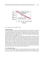
Volts). Fig. 1 shows the typical power production and distribution process.
Fig. 1. Typical Power Production and Distribution Process
Programmable Logic Controller
132
The electricity production process begins with its generation in power plants. The generated
electric power is supplied through step-up transformers to raise the voltage to HV of
transmission voltage before it is transmitted by transmission lines to transformer
substations.
The substations reduce the transmission voltage via power transformer in Main Intake
Distribution Substation (MIDS). MIDS is a node for terminating and reconfiguring
transformers that step down the HV transmission voltage to Primary Distribution Voltage
Level (PDVL).
The power is distributed from the transformer substations to the electric distribution
network via Main Switch Station (MSS). Basically MSS is a node for terminating and
reconfiguring the PDVL line of many feeders consisting of substations. In areas where
power needs to be delivered to consumers, the power transformers in the substation are
used to convert or step down the HV into a much lower voltage. Each feeder of MSS consists
of a few substations that stepped down to consumer voltage. Basically, the network
configuration for the distribution system is a loop circuit arrangement and each feeder
consists of substations separated into two parts by the NOP.
Fig. 2. An Example of Distribution Substation 11/0.415 kV
Most distribution systems are designed as either radial distribution system (Pabla, 2005) or
loop distribution system. In some countries like Malaysia, the electrical connection of the
substations is in the form of ring called “Ring (loop) Main Unit (RMU)”. RMU can be
obtained by arranging a primary loop, which provides power from two feeders. Any section
of the feeder can be isolated without interruption, and primary faults are reduced in
duration to the time required to locate a fault and do the necessary switching to restore
service. The connections are illustrated in Fig. 3 and Fig. 4.
Development of Customized Distribution Automation System (DAS)
for Secure Fault Isolation in Low Voltage Distribution System
133
Fig. 3. RMU connection
Fig. 4. Distribution Substation 11/0.415 kV
Substations serve as sources of energy supply for the local areas of distribution in which
they are located. Their main functions are to receive energy transmitted at HV from the
transmission lines, acted as nodal point from which the power or electricity can be changed
or distributed from it to the other substations or consumers and provide facilities for
switching. Substations are accessed by their incoming and outgoing switches connected by
other substations and allow the fault point due to the substation which affects in the system
that be isolated with switching method and the electricity remain supplied via other back up
supply. They provide points where safety devices may be installed to disconnect circuits or
equipment in the event of trouble. Some substations are equipped with EFI in order to locate
the fault point either from upstream or downstream.
2. Low voltage distribution system
The low voltage operating equipment and systems are susceptible to faults, malfunctions
and human errors. The solution to those problems lies on how the knowledgeable people
such as engineers handle and solve them in the best possible ways.
Programmable Logic Controller
134
The application of Automation system is one of the best solutions to those problems. In this
book, an application of automation system has been proposed and described applied into
practical LV systems for the solution of these problems.
However, the distribution systems have grown in an unplanned manner resulting in high
system losses in addition to poor quality of supply. The other reasons are the lack of use of
efficient tools for operational planning and advanced methodology for quick detection of
fault, isolation of the faulty section and service restoration. Currently, fault detection,
isolation and service restoration takes a long time causing the interruption of supply for a
longer duration.
SCADA can be used to handle the tasks which are currently handled by the people and can
reduce frequency of periodic visit of technical personal substantially. SCADA is a process
control system that enables a site operator to monitor and control processes that are
distributed among various remote sites. The control functions are related to switching
operations, such as switching a capacitor, or reconfiguring feeders. Once the fault location
has been analyzed, the automatic function for fault isolation and supply restoration is
executed. When the faulty line section is encountered, it is isolated, and the remaining
sections are energized. This function directly impacts the customers as well as the system
reliability.
This research is to develop a state of the art technology which targets all types of LV systems
and could be extended to lower voltage, medium voltage as well as higher voltage
applications in electrical, electronic, communication and mechatronics engineering.
In the early stage of introduction, distribution control technologies have lagged behind if
compared with advances in generation and transmission controls.
In Korea, the general structure of 154kV distribution substations using GIS standard. One
distribution substation is composed of fixed devices such as a few transmission lines, 154kV
double buses, two to four of 154kV/22.9kV main transformers, 22.9kV double structured
distribution bus, many distribution lines, and switching devices like CBs and line switches
(Lee & Park, 1996).
The fault point isolation is also based on the operation of corresponding relays and CBs but
the switching operation is done manually by the operators. KEPCO has suggested four step
processes to their operators. Step1 is to isolate the fault section using switches or CBs. Step 2
is to isolate black-out distribution line or transformers. Step 3 is to restore CBs one by one.
The system uses radial operation and load transfer is allowed up to 90% of capacity of each
transformer.
Bretas and Phadke (2003) proposed restoration scheme which composed of several Island
Restoration Schemes(IRS). Each IRS is composed of two ANNs and a switching sequence
program (SSP). The first ANN of each IRS is responsible for an island restoration load
forecast. The input of this ANN will be a normalized vector composed of the pre-
disturbance load. The second ANN of each IRS is responsible for the determination of the
final island configuration and the associated forecast restoration load pick up percentage
that will generate a feasible operational condition.
Hsu and Huang (1995) proposed ANN approach and pattern recognition method to provide
a proper restoration plan in a very short period. They investigated service restoration
following a fault on a distribution system within the service area of Taipei City District
Office of Taiwan Power Company. In this paper, they concluded that the required Central
Processing Unit (CPU) time using their method is much shorter than that required by the
heuristic approach of reference.
Development of Customized Distribution Automation System (DAS)
for Secure Fault Isolation in Low Voltage Distribution System
135
Huang C.M (2003) addressed multi objective service restoration problem (SRP) with a fuzzy
cause-effect network for minimizing a set of criteria, including the load not supplied and the
number of switching operations. All of them are converted into a single objective function
by giving relative weighting values for each criterion.
Hsiao et al (2000) proposed a reconfiguration for service restoration in a distribution system
using a combination of fuzzy logic and genetic algorithms. The objectives of the proposed
reconfiguration methodology were to maximize the load restored in the system and
minimize the switching operations for the reconfiguration. However, the methodology
proposed in this work is only applicable to radial power system.
3. Distribution automation system
The system architecture for this research is divided into three parts as shown in Fig. 5. The
first part involves investigation of SCADA equipment or HMI. PC is equipped with GUI
that runs under the Microsoft Windows XP platform using InduSoft software. The GUI
provides monitoring for service substation and customer service substation, real-time data,
data trending, data archiving, display and recoding alarm messages, show communication
status of the system and control execution. Systems operations personnel use this equipment
to control and monitor the I/O remotely.
Level 2 consists of I-7188EG embedded Ethernet. The control program is downloaded into
the controller. The logic programming for service substation and customer service
substation is almost identical. The logic programming is configured by using IsaGRAF
software manufactured by ICPDAS. I-7188EG is responsible for communicating with the
SCADA equipment using TCP/IP protocol. I-7188EG also acts as converter to link the
SCADA equipment to the I-7044 module, I-7051 module and I-7042 module using RS485
protocol. The controller also receives data from power analyzer by using RS-485 protocol.
Controller I-7188EG can handle control functions without the PC in real time.
Level 3 consists of I/O modules and three panels. The I/O modules are I-7044 module
which is an 8 channel digital output and 4 channel digital input module, I-7051 which is a 16
channel digital input and I-7042 which is a 13 channel digital output. I-7044 module receives
signal from ELCB in the customer service substation panel. It then converts the signal into
RS485 standard signal and transfers to RS485 network. This signal is received by I-7188EG
controller. I-7044 module receives signal from the controller to trigger certain actions to the
relays as output devices. I-7051 and I-7042 are responsible to receive and send signals to
I/O of service panel. Power analyzer is a power measurement metering device that displays
volts, amps, watt, vars and etc. It sends data directly to the controllers to be displayed at the
monitor.
In actual practice, service substation panel is connected to more than one customer service
substation panel. In this research, service substation panel is only connected to one customer
service substation panel. Customer service substation panel is connected to the consumer
panel. In this case, the consumer panel consists of lights as the control loads.
Fig. 6 shows a typical compact substation (PE) which is still use until today. This compact
substation fabricated by Schneider Electric Industries (M) Sdn Bhd. PE is also referred as
RMU. A 12KV, 630A, 20KVA RMU is supplying power supply to LV Feeder Panel. A three-
phase, 1000KVA, 11/0.433 kV transformer is used to step down 11kV to 433V before
supplying to LVFP.