Electric Machinery Fundamentals Power & Energy_9 doc
Bạn đang xem bản rút gọn của tài liệu. Xem và tải ngay bản đầy đủ của tài liệu tại đây (670.59 KB, 22 trang )
171
Chapter 7:
Induction Motors
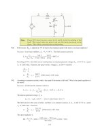
7-1. A dc test is performed on a 460-V ∆-connected 100-hp induction motor. If
DC
V
= 24 V and
DC
I
= 80 A,
what is the stator resistance
1
R
? Why is this so?
S
OLUTION
If this motor’s armature is connected in delta, then there will be two phases in parallel with one
phase between the lines tested.
R
1
R
1
R
1
V
DC
Therefore, the stator resistance
1
R
will be
()
()
11 1
DC
1
DC 1 1 1
2
3
RR R
V
R
IRRR
+
==
++
DC
1
DC
3324 V
0.45
2280 A
V
R
I
== =Ω
7-2. A 220-V, three-phase, two-pole, 50-Hz induction motor is running at a slip of 5 percent. Find:
(a) The speed of the magnetic fields in revolutions per minute
(b) The speed of the rotor in revolutions per minute
(c) The slip speed of the rotor
(d) The rotor frequency in hertz
S
OLUTION
(a) The speed of the magnetic fields is
()
sync
120 50 Hz
120
3000 r/min
2
e
f
n
P
== =
(b) The speed of the rotor is
() ( )( )
sync
1 1 0.05 3000 r/min 2850 r/min
m
nsn=− =− =
(c) The slip speed of the rotor is
()( )
slip sync
0.05 3000 r/min 150 r/minnsn== =
(d) The rotor frequency is
()()
slip
150 r/min 2
2.5 Hz
120 120
r
nP
f
== =
7-3. Answer the questions in Problem 7-2 for a 480-V, three-phase, four-pole, 60-Hz induction motor running at
a slip of 0.035.
S
OLUTION
(a) The speed of the magnetic fields is
172
(
)
sync
120 60 Hz
120
1800 r/min
4
e
f
n
P
== =
(b) The speed of the rotor is
() ( )( )
sync
1 1 0.035 1800 r/min 1737 r/min
m
nsn=− =− =
(c) The slip speed of the rotor is
()( )
slip sync
0.035 1800 r/min 63 r/minnsn== =
(d) The rotor frequency is
()()
slip
63 r/min 4
2.1 Hz
120 120
r
nP
f
== =
7-4. A three-phase, 60-Hz induction motor runs at 890 r/min at no load and at 840 r/min at full load.
(a) How many poles does this motor have?
(b) What is the slip at rated load?
(c) What is the speed at one-quarter of the rated load?
(d) What is the rotor’s electrical frequency at one-quarter of the rated load?
S
OLUTION
(a) This machine has 8 poles, which produces a synchronous speed of
()
sync
120 60 Hz
120
900 r/min
8
e
f
n
P
== =
(b) The slip at rated load is
sync
sync
900 840
100% 100% 6.67%
900
m
nn
s
n
−
−
=×= ×=
(c) The motor is operating in the linear region of its torque-speed curve, so the slip at ¼ load will be
0.25(0.0667) 0.0167s ==
The resulting speed is
() ( )( )
sync
1 1 0.0167 900 r/min 885 r/min
m
nsn=− =− =
(d) The electrical frequency at ¼ load is
()()
0.0167 60 Hz 1.00 Hz
re
fsf== =
7-5. A 50-kW, 440-V, 50-Hz, six-pole induction motor has a slip of 6 percent when operating at full-load
conditions. At full-load conditions, the friction and windage losses are 300 W, and the core losses are 600
W. Find the following values for full-load conditions:
(a) The shaft speed
n
m
(b) The output power in watts
(c) The load torque
load
τ
in newton-meters
(d) The induced torque
ind
τ
in newton-meters
173
(e) The rotor frequency in hertz
S
OLUTION
(a) The synchronous speed of this machine is
(
)
sync
120 50 Hz
120
1000 r/min
6
e
f
n
P
== =
Therefore, the shaft speed is
(
)
(
)
(
)
sync
1 1 0.06 1000 r/min 940 r/min
m
nsn=− =− =
(b) The output power in watts is 50 kW (stated in the problem).
(c) The load torque is
()
OUT
load
50 kW
508 N m
2 rad 1 min
940 r/min
1 r 60 s
m
P
τ
π
ω
== = ⋅
(d) The induced torque can be found as follows:
conv OUT F&W core misc
50 kW 300 W 600 W 0 W 50.9 kWPPPPP=+++= + + +=
()
conv
ind
50.9 kW
517 N m
2 rad 1 min
940 r/min
1 r 60 s
m
P
τ
π
ω
== = ⋅
(e) The rotor frequency is
()( )
0.06 50 Hz 3.00 Hz
re
fsf== =
7-6. A three-phase, 60-Hz, four-pole induction motor runs at a no-load speed of 1790 r/min and a full-load
speed of 1720 r/min. Calculate the slip and the electrical frequency of the rotor at no-load and full-load
conditions. What is the speed regulation of this motor [Equation (4-68)]?
S
OLUTION
The synchronous speed of this machine is 1800 r/min. The slip and electrical frequency at no-
load conditions is
sync nl
nl
sync
1800 1790
100% 100% 0.56%
1800
nn
s
n
−
−
=×= ×=
()()
,nl
0.0056 60 Hz 0.33 Hz
re
fsf== =
The slip and electrical frequency at full load conditions is
sync nl
fl
sync
1800 1720
100% 100% 4.44%
1800
nn
s
n
−
−
=×= ×=
()()
,fl
0.0444 60 Hz 2.67 Hz
re
fsf== =
The speed regulation is
nl fl
fl
1790 1720
SR 100% 100% 4.1%
1720
nn
n
−−
=×= ×=
7-7. A 208-V, two-pole, 60-Hz Y-connected wound-rotor induction motor is rated at 15 hp. Its equivalent
circuit components are
174
1
R = 0.200
Ω
2
R = 0.120
Ω
M
X = 15.0
Ω
1
X = 0.410
Ω
2
X = 0.410
Ω
mech
P = 250 W
misc
P
≈
0
core
P = 180 W
For a slip of 0.05, find
(a) The line current
L
I
(b) The stator copper losses
SCL
P
(c) The air-gap power
AG
P
(d) The power converted from electrical to mechanical form
conv
P
(e) The induced torque
ind
τ
(f) The load torque
load
τ
(g) The overall machine efficiency
(h) The motor speed in revolutions per minute and radians per second
S
OLUTION
The equivalent circuit of this induction motor is shown below:
0.20 Ω j0.41 Ω
+
-
V
φ
I
A
R
1
jX
1
R
2
−
s
s
R
1
2
jX
2
jX
M
0.120 Ωj0.41 Ω
j15 Ω
2.28 Ω
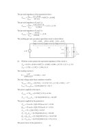
(a) The easiest way to find the line current (or armature current) is to get the equivalent impedance
F
Z
of the rotor circuit in parallel with
M
jX
, and then calculate the current as the phase voltage divided by the
sum of the series impedances, as shown below.
0.20 Ω j0.41 Ω
+
-
V
φ
I
A
R
1
jX
1
R
F
jX
F
The equivalent impedance of the rotor circuit in parallel with
M
jX is:
2
11
2.220 0.745 2.34 18.5
11 1 1
15 2.40 0.41
F
M
Zj
jX Z j j
== =+=∠°Ω
++
Ω+
The phase voltage is 208/
3 = 120 V, so line current
L
I is
175
11
120 0 V
0.20 0.41 2.22 0.745
LA
FF
V
II
RjXR jX j j
φ
∠°
== =
+++ Ω+ Ω+ Ω+ Ω
44.8 25.5 A
LA
II== ∠− °
(b) The stator copper losses are
()()
2
2
SCL 1
3 3 44.8 A 0.20 1205 W
A
PIR== Ω=
(c) The air gap power is
22
2
AG 2
33
AF
R
PI IR
s
==
(Note that
2
3
AF
IR
is equal to
2
2
2
3
R
I
s
, since the only resistance in the original rotor circuit was
2
/
Rs, and
the resistance in the Thevenin equivalent circuit is
F
R . The power consumed by the Thevenin equivalent
circuit must be the same as the power consumed by the original circuit.)
()( )
2
22
2
AG 2
3 3 3 44.8 A 2.220 13.4 kW
AF
R
PI IR
s
=== Ω=
(d) The power converted from electrical to mechanical form is
() ( )( )
conv AG
1 1 0.05 13.4 kW 12.73 kWPsP=− =− =
(e) The induced torque in the motor is
()
AG
ind
sync
13.4 kW
35.5 N m
2 rad 1 min
3600 r/min
1 r 60 s
P
τ
π
ω
== = ⋅
(f) The output power of this motor is
OUT conv mech core misc
12.73 kW 250 W 180 W 0 W 12.3 kWPPPPP=−−−= − − − =
The output speed is
() ( )( )
sync
1 1 0.05 3600 r/min 3420 r/min
m
nsn=− =− =
Therefore the load torque is
()
OUT
load
12.3 kW
34.3 N m
2 rad 1 min
3420 r/min
1 r 60 s
m
P
τ
π
ω
== = ⋅
(g) The overall efficiency is
OUT OUT
IN
100% 100%
3cos
A
PP
PVI
φ
η
θ
=× = ×
()( )
12.3 kW
100% 84.5%
3 120 V 44.8 A cos25.5
η
=×=
°
(h) The motor speed in revolutions per minute is 3420 r/min. The motor speed in radians per second is
()
2 rad 1 min
3420 r/min 358 rad/s
1 r 60 s
m
π
ω
==
7-8. For the motor in Problem 7-7, what is the slip at the pullout torque? What is the pullout torque of this
motor?
176
S
OLUTION
The slip at pullout torque is found by calculating the Thevenin equivalent of the input circuit
from the rotor back to the power supply, and then using that with the rotor circuit model.
()
()
(
)
(
)
()
11
TH
11
15 0.20 0.41
0.1895 0.4016 0.444 64.7
0.20 0.41 15
M
M
jX R jX j j
Zj
RjXX j
+ΩΩ+Ω
== =+Ω=∠°Ω
++ Ω+ Ω+Ω
()
(
)
()
()
TH
11
15
120 0 V 116.8 0.7 V
0.22 0.43 15
M
M
j
jX
RjXX j
φ
Ω
== ∠°=∠°
++ Ω+ Ω+Ω
VV
The slip at pullout torque is
()
2
max
2
2
TH TH 2
R
s
RXX
=
++
()( )
max
22
0.120
0.144
0.1895 0.4016 0.410
s
Ω
==
Ω+ Ω+ Ω
The pullout torque of the motor is
()
2
TH
max
2
2
sync TH TH TH 2
3V
RRXX
τ
ω
=
2+++
()
() ()( )
2
max
22
3 116.8 V
377 rad/s 0.1895 0.1895 0.4016 0.410
τ
=
2Ω+Ω+Ω+Ω
177
max
53.1 N m
τ
=⋅
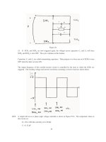
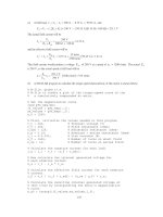
7-9. (a) Calculate and plot the torque-speed characteristic of the motor in Problem 7-7. (b) Calculate and plot
the output power versus speed curve of the motor in Problem 7-7.
S
OLUTION
(a) A MATLAB program to calculate the torque-speed characteristic is shown below.
% M-file: prob7_9a.m
% M-file create a plot of the torque-speed curve of the
% induction motor of Problem 7-7.
% First, initialize the values needed in this program.
r1 = 0.200; % Stator resistance
x1 = 0.410; % Stator reactance
r2 = 0.120; % Rotor resistance
x2 = 0.410; % Rotor reactance
xm = 15.0; % Magnetization branch reactance
v_phase = 208 / sqrt(3); % Phase voltage
n_sync = 3600; % Synchronous speed (r/min)
w_sync = 377; % Synchronous speed (rad/s)
% Calculate the Thevenin voltage and impedance from Equations
% 7-41a and 7-43.
v_th = v_phase * ( xm / sqrt(r1^2 + (x1 + xm)^2) );
z_th = ((j*xm) * (r1 + j*x1)) / (r1 + j*(x1 + xm));
r_th = real(z_th);
x_th = imag(z_th);
% Now calculate the torque-speed characteristic for many
% slips between 0 and 1. Note that the first slip value
% is set to 0.001 instead of exactly 0 to avoid divide-
% by-zero problems.
s = (0:1:50) / 50; % Slip
s(1) = 0.001;
nm = (1 - s) * n_sync; % Mechanical speed
% Calculate torque versus speed
for ii = 1:51
t_ind(ii) = (3 * v_th^2 * r2 / s(ii)) /
(w_sync * ((r_th + r2/s(ii))^2 + (x_th + x2)^2) );
end
% Plot the torque-speed curve
figure(1);
plot(nm,t_ind,'k-','LineWidth',2.0);
xlabel('\bf\itn_{m}');
ylabel('\bf\tau_{ind}');
title ('\bfInduction Motor Torque-Speed Characteristic');
grid on;
The resulting plot is shown below:
178
0 500 1000 1500 2000 2500 3000 3500 4000
0
10
20
30
40
50
60
n
m
τ
ind
Induction Motor Torque-Speed Characteristic
(b) A MATLAB program to calculate the output-power versus speed curve is shown below.
% M-file: prob7_9b.m
% M-file create a plot of the output pwer versus speed
% curve of the induction motor of Problem 7-7.
% First, initialize the values needed in this program.
r1 = 0.200; % Stator resistance
x1 = 0.410; % Stator reactance
r2 = 0.120; % Rotor resistance
x2 = 0.410; % Rotor reactance
xm = 15.0; % Magnetization branch reactance
v_phase = 208 / sqrt(3); % Phase voltage
n_sync = 3600; % Synchronous speed (r/min)
w_sync = 377; % Synchronous speed (rad/s)
% Calculate the Thevenin voltage and impedance from Equations
% 7-41a and 7-43.
v_th = v_phase * ( xm / sqrt(r1^2 + (x1 + xm)^2) );
z_th = ((j*xm) * (r1 + j*x1)) / (r1 + j*(x1 + xm));
r_th = real(z_th);
x_th = imag(z_th);
% Now calculate the torque-speed characteristic for many
% slips between 0 and 1. Note that the first slip value
% is set to 0.001 instead of exactly 0 to avoid divide-
% by-zero problems.
s = (0:1:50) / 50; % Slip
s(1) = 0.001;
nm = (1 - s) * n_sync; % Mechanical speed (r/min)
wm = (1 - s) * w_sync; % Mechanical speed (rad/s)
% Calculate torque and output power versus speed
for ii = 1:51
179
t_ind(ii) = (3 * v_th^2 * r2 / s(ii)) /
(w_sync * ((r_th + r2/s(ii))^2 + (x_th + x2)^2) );
p_out(ii) = t_ind(ii) * wm(ii);
end
% Plot the torque-speed curve
figure(1);
plot(nm,p_out/1000,'k-','LineWidth',2.0);
xlabel('\bf\itn_{m} \rm\bf(r/min)');
ylabel('\bf\itP_{OUT} \rm\bf(kW)');
title ('\bfInduction Motor Ouput Power versus Speed');
grid on;
The resulting plot is shown below:
7-10. For the motor of Problem 7-7, how much additional resistance (referred to the stator circuit) would it be
necessary to add to the rotor circuit to make the maximum torque occur at starting conditions (when the
shaft is not moving)? Plot the torque-speed characteristic of this motor with the additional resistance
inserted.
S
OLUTION
To get the maximum torque at starting, the
max
s
must be 1.00. Therefore,
()
2
max
2
2
TH TH 2
R
s
RXX
=
++
()( )
2
22
1.00
0.1895 0.4016 0.410
R
=
Ω+ Ω+ Ω
2
0.833 R =Ω
Since the existing resistance is 0.120
Ω
, an additional 0.713
Ω
must be added to the rotor circuit. The
resulting torque-speed characteristic is:
180
7-11. If the motor in Problem 7-7 is to be operated on a 50-Hz power system, what must be done to its supply
voltage? Why? What will the equivalent circuit component values be at 50 Hz? Answer the questions in
Problem 7-7 for operation at 50 Hz with a slip of 0.05 and the proper voltage for this machine.
S
OLUTION
If the input frequency is decreased to 50 Hz, then the applied voltage must be decreased by 5/6
also. If this were not done, the flux in the motor would go into saturation, since
∫
=
T
dtv
N
1
φ
and the period T would be increased. At 50 Hz, the resistances will be unchanged, but the reactances will
be reduced to 5/6 of their previous values. The equivalent circuit of the induction motor at 50 Hz is shown
below:
0.20 Ω j0.342 Ω
+
-
V
φ
I
A
R
1
jX
1
R
2
−
s
s
R
1
2
jX
2
jX
M
0.120 Ωj0.342 Ω
j12.5 Ω
2.28 Ω
(a) The easiest way to find the line current (or armature current) is to get the equivalent impedance
F
Z
of the rotor circuit in parallel with
M
jX , and then calculate the current as the phase voltage divided by the
sum of the series impedances, as shown below.
181
0.20 Ω j0.342 Ω
+
-
V
φ
I
A
R
1
jX
1
R
F
jX
F
The equivalent impedance of the rotor circuit in parallel with
M
jX is:
2
11
2.197 0.744 2.32 18.7
11 1 1
12.5 2.40 0.342
F
M
Zj
jX Z j j
== =+=∠°Ω
++
Ω+
The line voltage must be derated by 5/6, so the new line voltage is 173.3 V
T
V = . The phase voltage is
173.3 /
3
= 100 V, so line current
L
I is
11
100 0 V
0.20 0.342 2.197 0.744
LA
FF
V
II
RjXR jX j j
φ
∠°
== =
+++ Ω+Ω+Ω+Ω
38.0 24.4 A
LA
II== ∠− °
(b) The stator copper losses are
()( )
2
2
SCL 1
3 3 38 A 0.20 866 W
A
PIR== Ω=
(c) The air gap power is
22
2
AG 2
33
AF
R
PI IR
s
==
(Note that
2
3
AF
IR
is equal to
2
2
2
3
R
I
s
, since the only resistance in the original rotor circuit was
2
/
Rs, and
the resistance in the Thevenin equivalent circuit is
F
R . The power consumed by the Thevenin equivalent
circuit must be the same as the power consumed by the original circuit.)
()( )
2
22
2
AG 2
3 3 3 38 A 2.197 9.52 kW
AF
R
PI IR
s
=== Ω=
(d) The power converted from electrical to mechanical form is
() ( )( )
conv AG
1 1 0.05 9.52 kW 9.04 kWPsP=− =− =
(e) The induced torque in the motor is
()
AG
ind
sync
9.52 kW
30.3 N m
2 rad 1 min
3000 r/min
1 r 60 s
P
τ
π
ω
== = ⋅
(f) In the absence of better information, we will treat the mechanical and core losses as constant despite
the change in speed. This is not true, but we don’t have reason for a better guess. Therefore, the output
power of this motor is
OUT conv mech core misc
9.04 kW 250 W 180 W 0 W 8.61 kWPPPPP=−−−= − − − =
The output speed is
() ( )( )
sync
1 1 0.05 3000 r/min 2850 r/min
m
nsn=− =− =
182
Therefore the load torque is
()
OUT
load
8.61 kW
28.8 N m
2 rad 1 min
2850 r/min
1 r 60 s
m
P
τ
π
ω
== = ⋅
(g) The overall efficiency is
OUT OUT
IN
100% 100%
3cos
A
PP
PVI
φ
η
θ
=× = ×
()( )
8.61 kW
100% 82.9%
3 100 V 38.0 A cos 24.4
η
=×=
°
(h) The motor speed in revolutions per minute is 2850 r/min. The motor speed in radians per second is
()
2 rad 1 min
2850 r/min 298.5 rad/s
1 r 60 s
m
π
ω
==
7-12. Figure 7-18a shows a simple circuit consisting of a voltage source, a resistor, and two reactances. Find the
Thevenin equivalent voltage and impedance of this circuit at the terminals. Then derive the expressions for
the magnitude of
V
TH
and for R
TH
given in Equations (7-41b) and (7-44).
S
OLUTION
The Thevenin voltage of this circuit is
()
TH
11
M
M
jX
RjXX
φ
=
++
VV
The magnitude of this voltage is
()
TH
2
2
11
M
M
X
VV
RXX
φ
=
++
If
1M
XX>>
, then
()()
22
2
11 1
MM
RXX XX++ ≈+
, so
TH
1
M
M
X
VV
XX
φ
≈
+
The Thevenin impedance of this circuit is
()
()
11
TH
11
M
M
jX R jX
Z
RjXX
+
=
++
183
()( )
() ()
111 1
TH
11 11
MM
MM
jX R jX R j X X
Z
RjXX RjXX
+−+
=
++ −+
()
222 2
11 11 1 1 1 1
TH
2
2
11
MMM MMM
M
RX X RX X RX j R X X X X X
Z
RXX
−+++ ++
=
++
() ()
2222
1 111
TH TH TH
22
22
11 11
MMMM
MM
RX R X X X XX
ZRjX j
RXX RXX
++
=+ = +
++ ++
The Thevenin resistance is
()
2
1
TH
2
2
11
M
M
RX
R
RXX
=
++
. If
1M
XR>> , then
()()
22
2
11 1
MM
RXX XX++ ≈+
,
so
2
TH 1
1
M
M
X
RR
XX
≈
+
The Thevenin reactance is
()
22 2
111
TH
2
2
11
MMM
M
RX X X XX
X
RXX
++
=
++
.
If
1M
XR>> and
1M
XX>> then
22 2
111MMM
XX R X X X>> + and
()
2
22
11
MM
XX X R+≈>>
, so
2
1
TH 1
2
M
M
XX
XX
X
≈=
7-13. Figure P7-1 shows a simple circuit consisting of a voltage source, two resistors, and two reactances in
parallel with each other. If the resistor
R
L
is allowed to vary but all the other components are constant, at
what value of
R
L
will the maximum possible power be supplied to it? Prove your answer. (Hint: Derive
an expression for load power in terms of V,
R
S
, X
S
, R
L
and X
L
and take the partial derivative of that
expression with respect to
R
L
.) Use this result to derive the expression for the pullout torque [Equation (7-
54)].
S
OLUTION
The current flowing in this circuit is given by the equation
L
SSLL
RjXRjX
=
+++
V
I
()( )
22
L
SL S L
V
I
RR X X
=
+++
The power supplied to the load is
184
()( )
2
2
22
L
LL
SL S L
VR
PIR
RR X X
==
+++
()( ) ()
()( )
22
22
2
22
2
SL S L L SL
L
SL S L
RR X X VVR RR
P
R
RR X X
+++ − +
∂
=
∂
+++
To find the point of maximum power supplied to the load, set /
L
PR∂∂ = 0 and solve for
L
R .
()( ) ()
22
22
20
SL S L L SL
RR X X VVR RR
+++ − +=
()( ) ()
22
2
SL S L LSL
RR X X RRR
+++ = +
()
2
22 2
222
SSLLSL SLL
RRRRXX RRR++++=+
()
2
22 2
2
SL SL L
RR XX R++ + =
()
2
22
SSLL
RXX R++ =
Therefore, for maximum power transfer, the load resistor should be
()
2
2
LS SL
RRXX=++
7-14. A 440-V 50-Hz two-pole Y-connected induction motor is rated at 75 kW. The equivalent circuit
parameters are
1
R = 0.075
Ω
2
R = 0.065
Ω
M
X = 7.2
Ω
1
X = 0.17
Ω
2
X = 0.17
Ω
F&W
P
= 1.0 kW
misc
P
= 150 W
core
P
= 1.1 kW
For a slip of 0.04, find
(a) The line current
L
I
(b) The stator power factor
(c) The rotor power factor
(d) The stator copper losses
SCL
P
(e) The air-gap power
AG
P
(f) The power converted from electrical to mechanical form
conv
P
(g) The induced torque
ind
τ
(h) The load torque
load
τ
(i) The overall machine efficiency
η
(j) The motor speed in revolutions per minute and radians per second
S
OLUTION
The equivalent circuit of this induction motor is shown below:
185
0.075 Ω j0.17 Ω
+
-
V
φ
I
A
R
1
jX
1
R
2
−
s
s
R
1
2
jX
2
jX
M
0.065 Ωj0.17 Ω
j7.2 Ω
1.56 Ω
(a) The easiest way to find the line current (or armature current) is to get the equivalent impedance
F
Z
of the rotor circuit in parallel with
M
jX
, and then calculate the current as the phase voltage divided by the
sum of the series impedances, as shown below.
0.075 Ω j0.17 Ω
+
-
V
φ
I
A
R
1
jX
1
R
F
jX
F
The equivalent impedance of the rotor circuit in parallel with
M
jX is:
2
11
1.539 0.364 1.58 13.2
11 1 1
7.2 1.625 0.17
F
M
Zj
jX Z j j
== =+=∠°Ω
++
Ω+
The phase voltage is 440/
3
= 254 V, so line current
L
I
is
11
254 0 V
0.075 0.17 1.539 0.364
LA
FF
V
II
RjXR jX j j
φ
∠°
== =
+++ Ω+ Ω+ Ω+ Ω
149.4 18.3 A
LA
II== ∠− °
(b) The stator power factor is
()
PF cos 18.3 0.949 lagging=°=
(c) To find the rotor power factor, we must find the impedance angle of the rotor
11
2
2
0.17
tan tan 5.97
/1.625
R
X
Rs
θ
−−
===°
Therefore the rotor power factor is
PF cos5.97 0.995 lagging
R
=°=
(d) The stator copper losses are
()()
2
2
SCL 1
3 3 149.4 A 0.075 1675 W
A
PIR== Ω=
(e) The air gap power is
22
2
AG 2
33
AF
R
PI IR
s
==
186
(Note that
2
3
AF
IR
is equal to
2
2
2
3
R
I
s
, since the only resistance in the original rotor circuit was
2
/
Rs
, and
the resistance in the Thevenin equivalent circuit is
F
R . The power consumed by the Thevenin equivalent
circuit must be the same as the power consumed by the original circuit.)
()()
2
22
2
AG 2
3 3 3 149.4 A 1.539 103 kW
AF
R
PI IR
s
=== Ω=
(f) The power converted from electrical to mechanical form is
() ( )( )
conv AG
1 1 0.04 103 kW 98.9 kWPsP=− =− =
(g) The synchronous speed of this motor is
()
sync
120 50 Hz
120
3000 r/min
2
e
f
n
P
== =
()
sync
2 rad 1 min
3000 r/min 314 rad/s
1 r 60 s
π
ω
==
Therefore the induced torque in the motor is
()
AG
ind
sync
103 kW
327.9 N m
2 rad 1 min
3000 r/min
1 r 60 s
P
τ
π
ω
== = ⋅
(h) The output power of this motor is
OUT conv mech core misc
98.8 kW 1.0 kW 1.1 kW 150 W 96.6 kWPPPPP=−−−= − − − =
The output speed is
() ( )( )
sync
1 1 0.04 3000 r/min 2880 r/min
m
nsn=− =− =
Therefore the load torque is
()
OUT
load
98.8 kW
327.6 N m
2 rad 1 min
2880 r/min
1 r 60 s
m
P
τ
π
ω
== = ⋅
(i) The overall efficiency is
OUT OUT
IN
100% 100%
3cos
A
PP
PVI
φ
η
θ
=× = ×
()( )()
96.6 kW
100% 89.4%
3 254 V 149.4 A cos 18.3
η
=×=
°
(j) The motor speed in revolutions per minute is 2880 r/min. The motor speed in radians per second is
()
2 rad 1 min
2880 r/min 301.6 rad/s
1 r 60 s
m
π
ω
==
7-15.
For the motor in Problem 7-14, what is the pullout torque? What is the slip at the pullout torque? What is
the rotor speed at the pullout torque?
S
OLUTION
The slip at pullout torque is found by calculating the Thevenin equivalent of the input circuit
from the rotor back to the power supply, and then using that with the rotor circuit model.
187
()
()
()( )
()
11
TH
11
7.2 0.075 0.17
0.0731 0.1662 0.182 66.3
0.075 0.17 7.2
M
M
jX R jX
jj
Zj
RjXX j
+
ΩΩ+Ω
== =+Ω=∠°Ω
++ Ω+ Ω+Ω
()
()
()
()
TH
11
7.2
254 0 V 248 0.06 V
0.075 0.17 7.2
M
M
j
jX
RjXX j
φ
Ω
== ∠°=∠°
++ Ω+ Ω+Ω
VV
The slip at pullout torque is
()
2
max
2
2
TH TH 2
R
s
RXX
=
++
()( )
max
22
0.065
0.189
0.0731 0.1662 0.17
s
Ω
==
Ω+ Ω+ Ω
The pullout torque of the motor is
()
+++2
=
2
2TH
2
THTHsync
2
TH
max
3
XXRR
V
ω
τ
()
() ()( )
2
max
22
3248 V
314.2 rad/s 0.0731 0.0731 0.1662 0.17
τ
=
2Ω+Ω+Ω+Ω
max
704 N m
τ
=⋅
7-16. If the motor in Problem 7-14 is to be driven from a 440-V 60-Hz power supply, what will the pullout
torque be? What will the slip be at pullout?
S
OLUTION
If this motor is driven from a 60 Hz source, the resistances will be unchanged and the reactances
will be increased by a ratio of 6/5. The resulting equivalent circuit is shown below.
0.075 Ω j0.204 Ω
+
-
V
φ
I
A
R
1
jX
1
R
2
−
s
s
R
1
2
jX
2
jX
M
0.065 Ωj0.204 Ω
j8.64 Ω
1.56 Ω
The slip at pullout torque is found by calculating the Thevenin equivalent of the input circuit from the rotor
back to the power supply, and then using that with the rotor circuit model.
()
()
()( )
()
11
TH
11
8.64 0.075 0.204
0.0731 0.1994 0.212 69.9
0.075 0.204 8.64
M
M
jX R jX j j
Zj
RjXX j
+ΩΩ+Ω
== =+Ω=∠°Ω
++ Ω+ Ω+Ω
()
()
()
()
TH
11
8.64
254 0 V 248 0.05 V
0.075 0.204 8.64
M
M
j
jX
RjXX j
φ
Ω
== ∠°=∠°
++ Ω+ Ω+Ω
VV
The slip at pullout torque is
()
2
max
2
2
TH TH 2
R
s
RXX
=
++
188
()( )
max
22
0.065
0.159
0.0731 0.1994 0.204
s
Ω
==
Ω+ Ω+ Ω
The synchronous speed of this motor is
()
sync
120 60 Hz
120
3600 r/min
2
e
f
n
P
== =
()
sync
2 rad 1 min
3600 r/min 377 rad/s
1 r 60 s
π
ω
==
Therefore the pullout torque of the motor is
()
2
TH
max
2
2
sync TH TH TH 2
3V
RRXX
τ
ω
=
2+++
()
() ()( )
2
max
22
3248 V
377 rad/s 0.0731 0.0731 0.1994 0.204
τ
=
2Ω+Ω+Ω+Ω
max
507 N m
τ
=⋅
7-17. Plot the following quantities for the motor in Problem 7-14 as slip varies from 0% to 10%: (a)
ind
τ
(b)
conv
P (c)
out
P (d) Efficiency
η
. At what slip does
out
P equal the rated power of the machine?
S
OLUTION
This problem is ideally suited to solution with a MATLAB program. An appropriate program is
shown below. It follows the calculations performed for Problem 7-14, but repeats them at many values of
slip, and then plots the results. Note that it plots all the specified values versus
m
n , which varies from
2700 to 3000 r/min, corresponding to a range of 0 to 10% slip.
% M-file: prob7_17.m
% M-file create a plot of the induced torque, power
% converted, power out, and efficiency of the induction
% motor of Problem 7-14 as a function of slip.
% First, initialize the values needed in this program.
r1 = 0.075; % Stator resistance
x1 = 0.170; % Stator reactance
r2 = 0.065; % Rotor resistance
x2 = 0.170; % Rotor reactance
xm = 7.2; % Magnetization branch reactance
v_phase = 440 / sqrt(3); % Phase voltage
n_sync = 3000; % Synchronous speed (r/min)
w_sync = 314.2; % Synchronous speed (rad/s)
p_mech = 1000; % Mechanical losses (W)
p_core = 1100; % Core losses (W)
p_misc = 150; % Miscellaneous losses (W)
% Calculate the Thevenin voltage and impedance from Equations
% 7-41a and 7-43.
v_th = v_phase * ( xm / sqrt(r1^2 + (x1 + xm)^2) );
z_th = ((j*xm) * (r1 + j*x1)) / (r1 + j*(x1 + xm));
r_th = real(z_th);
x_th = imag(z_th);
189
% Now calculate the torque-speed characteristic for many
% slips between 0 and 0.1. Note that the first slip value
% is set to 0.001 instead of exactly 0 to avoid divide-
% by-zero problems.
s = (0:0.001:0.1); % Slip
s(1) = 0.001;
nm = (1 - s) * n_sync; % Mechanical speed
wm = nm * 2*pi/60; % Mechanical speed
% Calculate torque, P_conv, P_out, and efficiency
% versus speed
for ii = 1:length(s)
% Induced torque
t_ind(ii) = (3 * v_th^2 * r2 / s(ii)) /
(w_sync * ((r_th + r2/s(ii))^2 + (x_th + x2)^2) );
% Power converted
p_conv(ii) = t_ind(ii) * wm(ii);
% Power output
p_out(ii) = p_conv(ii) - p_mech - p_core - p_misc;
% Power input
zf = 1 / ( 1/(j*xm) + 1/(r2/s(ii)+j*x2) );
ia = v_phase / ( r1 + j*x1 + zf );
p_in(ii) = 3 * v_phase * abs(ia) * cos(atan(imag(ia)/real(ia)));
% Efficiency
eff(ii) = p_out(ii) / p_in(ii) * 100;
end
% Plot the torque-speed curve
figure(1);
plot(nm,t_ind,'b-','LineWidth',2.0);
xlabel('\bf\itn_{m} \rm\bf(r/min)');
ylabel('\bf\tau_{ind} \rm\bf(N-m)');
title ('\bfInduced Torque versus Speed');
grid on;
% Plot power converted versus speed
figure(2);
plot(nm,p_conv/1000,'b-','LineWidth',2.0);
xlabel('\bf\itn_{m} \rm\bf(r/min)');
ylabel('\bf\itP\rm\bf_{conv} (kW)');
title ('\bfPower Converted versus Speed');
grid on;
% Plot output power versus speed
figure(3);
plot(nm,p_out/1000,'b-','LineWidth',2.0);
xlabel('\bf\itn_{m} \rm\bf(r/min)');
ylabel('\bf\itP\rm\bf_{out} (kW)');
title ('\bfOutput Power versus Speed');
axis([2700 3000 0 180]);
190
grid on;
% Plot the efficiency
figure(4);
plot(nm,eff,'b-','LineWidth',2.0);
xlabel('\bf\itn_{m} \rm\bf(r/min)');
ylabel('\bf\eta (%)');
title ('\bfEfficiency versus Speed');
grid on;
The four plots are shown below:
2700 2750 2800 2850 2900 2950 3000
0
100
200
300
400
500
600
700
n
m
(r/min)
τ
ind
(N-m)
Induced Torque versus Speed
191
This machine is rated at 75 kW. It produces an output power of 75 kW at 3.1% slip, or a speed of 2907
r/min.
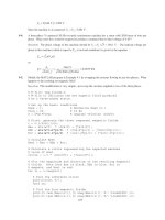
7-18. A 208-V, 60 Hz, six-pole Y-connected 25-hp design class B induction motor is tested in the laboratory,
with the following results:
No load: 208 V, 22.0 A, 1200 W, 60 Hz
Locked rotor: 24.6 V, 64.5 A, 2200 W, 15 Hz
DC test: 13.5 V, 64 A
Find the equivalent circuit of this motor, and plot its torque-speed characteristic curve.
192
S
OLUTION
From the DC test,
1
13.5 V
2
64 A
R =
⇒
1
0.105 R =Ω
R
1
R
1
R
1
V
DC
+
-
I
DC
In the no-load test, the line voltage is 208 V, so the phase voltage is 120 V. Therefore,
1
,nl
120 V
5.455 @ 60 Hz
22.0 A
M
A
V
XX
I
φ
+= = = Ω
In the locked-rotor test, the line voltage is 24.6 V, so the phase voltage is 14.2 V. From the locked-rotor
test at 15 Hz,
LR LR LR
,LR
14.2 V
0.2202
64.5 A
A
V
ZRjX
I
φ
=+ = = = Ω
′′
()()
11
LR
LR
LR
2200 W
cos cos 36.82
3 24.6 V 64.5 A
P
S
θ
−−
== =°
′
Therefore,
()()
LR LR LR
cos 0.2202 cos 36.82 0.176 RZ
θ
==Ω°=Ω′
⇒
12
0.176 RR+= Ω
⇒
2
0.071 R =Ω
()()
LR LR LR
in 0.2202 sin 36.82 0.132 XZs
θ
==Ω°=Ω′′
At a frequency of 60 Hz,
LR LR
60 Hz
0.528
15 Hz
XX
==Ω
′
For a Design Class B motor, the split is
1
0.211 X =Ω and
2
0.317 X =Ω. Therefore,
5.455 0.211 5.244
M
X =Ω−Ω= Ω
The resulting equivalent circuit is shown below: