Cutting Tool Technology Industrial Handbook by Graham T Smith_4 potx
Bạn đang xem bản rút gọn của tài liệu. Xem và tải ngay bản đầy đủ của tài liệu tại đây (628.44 KB, 9 trang )
is the strain-hardening tendency of the workpiece
material. erefore, the greater the strain-harden-
ing exponent, the higher will be its BUE formation.
From experiments conducted on BUE formation, it
would seem that the higher the cutting speed, the
less is the tendency for BUE to form. Whether this
lack of BUE formation at higher cutting data is the
consequence of increased strain rate, or the result
of higher interface temperatures is somewhat open
to debate. However, it would seem that a paradox
exists, because as the speed increases, the tempera-
ture will also increase, but the BUE decreases. e
propensity for BUE formation can be lessened by:
I. Changing the geometry of the cutting edge –
by either increasing the tool’s rake angle, or de-
creasing the D
OC
, or both,
II. Utilising a smaller cutting tip radius,
III. Using an eective cutting uid, or
IV. Any combination of these factors.
•
Discontinuous chips – consist of adjacent work-
piece chip segments that are usually either loosely
attached to each other, or totally fragment as they
are cut (Fig. 29). e formation of discontinuous
chips usually occur under the following machining
conditions:
I. Brittle workpiece materials
– these materials
do not have the machining capability to un-
dergo the high shear strains,
II. Hard particles and impurities
– materials with
these in their matrix, will act as ‘stress-raisers’
and actively encourage chip breakage,
III. Very high, or low cutting speeds
– chip veloc-
ity at both ends of the cutting spectrum, will
result in lack of adherence/fragmentation of
the chip segments,
IV. Low rake angles/large D
OC
’s – either small top
rakes and heavy D
OC
’s will decrease the adher-
ence of the adjacent chip segments,
V. Ineective cutting uid
– poor lubricity, com-
bined with a meagre wetting ability, will en-
courage discontinuity of chip segments,
VI. Inadequate machine tool stiness
– creating
vibrational tendencies and cutting instability,
leading to disruption of the machining dynam-
ics and loosening of chip segments.
As mentioned in ‘Roman II’ above, the hard particles
and impurities tend to act as crack nucleation sites,
therefore creating discontinuous chips. Large D
OC
’s
increase the probability that such defects occur in the
cutting zone, thereby aiding discontinuous chip for-
mation. While, faster cutting speeds result in higher
localised temperatures, causing greater ductility in the
chip, lessening the tendency for the formation of dis-
continuous chips. If the magnitude of the compressive
stresses in the both the primary and secondary shear
zones signicantly increase, the applied forces aid in
discontinuous chip formation, this is because of the
fact that the maximum shear strain will increase, due
to the presence of an increased compressive stress.
NB
Due to the nature of discontinuous chip forma-
tion, if the workpiece-tool-machine loop is not su-
ciently sti, this will generate vibrational and chatter
tendencies, which can result in an excessive tool wear
regime, or machined component surface damage.
•
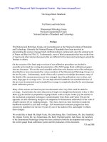
Segmented chips – are sometimes termed: in-, or
non-homogeneous chips, or serrated chips. is
chip form has the characteristic saw-toothed pro-
le which is noted by zones of low and high shear
strain (Fig. 30). ese workpiece materials possess
low thermal conductivity, as such, when machined
their mechanical strength will drastically decrease
with higher temperatures. is continuous thermal
cycle of both fracture and rewelding in a very nar-
row region, creates the saw-toothed prole, being
particular relevant for titanium and its alloys and
certain stainless steel grades. For example, to ex-
plain what happens in realistic machining situation,
the specimen Fig. 30a is displayed, for an austenitic
stainless steel quick-stop micrograph. is micro-
graph being the result of a less than continuous ma-
chining process (1), utilising a 5° top rake-angled
turning insert. Here, variations in the cutting pro-
cess have created uctuations in the cutting forces,
resulting in waviness of the machined surface (2).
Prior to the material yielding, then the shearing
process occurring, the workpiece material has de-
formed against the cutting edge (3). To explain how
changing the top rake angle inuences the resul-
tant chip formation for an identical stainless steel
workpiece material, Fig. 30b is shown. Machining
has now been undertaken with a 15° top rake, pro-
moting a more continuous machining process than
was apparent with the 5° tool (i.e. illustrated in Fig.
30a). is more ecient cutting process, results in
smaller variations in the cutting forces (1 and 2).
e chip is seen to ow over the rake face in a more
Chapter
Figure 29. Discontinuous chip formation. [Courtesy of Sumitomo Electric Hardmetal Ltd.].
Turning and Chip-breaking Technology
consistent manner (3). It was found with this work-
piece material in an experimental cutting proce-
dure, that the tangential cutting force component,
was closer to the actual cutting edge than when
similar machining was undertaken on unalloyed
steel specimens.
NB e cutting data for machining the stain-
less steel specimens in Figs. 30 a and b, were:
180 m min
–1
cutting speed, 0.3 mm rev
–1
feedrate,
3 mm D
OC
.
2.4 Tool Nose Radius
e insert’s nose radius has been previously mentioned
in Section 2.1.6, concerning: Cutting Tool holder/In-
sert Selection. Moreover, the top rake geometry of the
cutting insert will signicantly aect the chip forma-
tion process, particularly when prole turning. In Fig.
31a, a spherically-shaped component is being ‘prole
machined’ using a large nose-radiused turning insert.
Here, as the component nears its true geometric cur-
vature, the cutting insert forces will uctuate continu-
Figure 30. Segmented chip formation, resulting from machining stainless steel and the work-hardening zone
– which is aected by the sharpness of the insert’s edge. [Courtesy of Sandvik Coromant]
.
Chapter
Figure 31. The cutting insert’s tool nose radius when either proling, or general turning, will modify both the prole and
diameter as ank wear occurs. [Courtesy of Sandvik Coromant]
.
Turning and Chip-breaking Technology
ously as the insert progresses (i.e circular interpolates
with the X- and Z-axes of the machine tool) around
the curved prole. If the geometry of the tool was not
itself of round geometry, then the ‘point-contact’ could
not be maintained, leading to signicant variations in
chip formation. If this lack of tool-work contact were
not to occur, then the machined prole would be
compromised and due to insucient chip control, the
actual cut surface prole would not have a consistent
and accurate surface texture.
e machined surface texture generated by the pas-
sage of the cutting insert’s geometry, is to a large extent
the product of the relationship, between the nose ra-
dius and the feedrate and, to a lesser degree the cutting
speed and its tool wear pattern. e size of the tool
nose radius will have quite an eect on the surface tex-
ture produced, if the feedrate is set, then a small nose
radius will create a dierent workpiece surface texture
to that of a larger one (see Fig. 31b). Moreover, if a
large nose radius is selected for a lighter D
OC
, or if the
feed is equal to the nose radius, then this larger nose
geometry will be superior to that of a smaller tool nose
radius. is is because the ‘larger nose’ oers a smaller
plan approach angle, having the pressure of the cut
distributed across a longer cut length, creating an en-
hanced surface texture. ere are several disadvan-
tages to utilising a larger tool nose radius geometry,
these are that the:
•
Chip formed becomes more dicult to bend and
eectively break,
•
Radial cutting forces are greater,
•
Power consumption increases,
•
Rigidity of the set-up is necessary – leading to pos-
sible vibrational tendencies on either weaker, or
unstable workpieces.
Tool wear (i.e. denoted by ‘∆’ in Figs. 31ci and cii) and
in particular ank wear
25
, can signicantly inuence
the resulting machined component dimensional accu-
racy (Fig. 31cii), which on a batch of components cut
with the same insert, will result in some level of ‘tool
25 Flank wear is normally denoted by specic ‘zones’ – more will
be said on this topic later – but, in this example, the tool’s in-
sert wear ‘V
B
’ is shown in both Figs. 31ci and cii.
dri’ which could aect the process capability
26
of the
overall parts produced. is ank wear ‘V
B
’ can be cal-
culated and utilised to determine the anticipated tool’s
life (ie, in-cut), this important factor in production
machining operational procedure, will be discussed in
due course.
Wiper blades (Fig. 32) are not a new insert geom-
etry concept, they have been used for face milling op-
erations for quiet a long time, but only in recent years
are they being utilised for component nish turning.
e principle underlying a wiper insert for turning op-
erations, concerns the application of a modied ‘tool
nose radius’ (see Fig. 32 – bottom le and right dia-
grams). When a ‘standard’ tool nose geometry insert
is used (i.e. Fig. 32 – bottom le), it creates a series of
peaks and valleys (i.e. termed ‘cusps’
27
) aer the pas-
sage of the ‘insert nose’ over the machined surface.
Conversely, a cutting insert with wiper blade geom-
etry (i.e. Fig. 32 – bottom right), has trailing radii that
blends – beyond the tangency point – with the tool
nose radius which remains in contact with the work-
piece, allowing it to wipe (i.e. smooth) the peaks, leav-
ing a superior machined surface texture.
In the past, wiper insert geometries were only em-
ployed for surface improvement in nishing opera-
26 Process capability denoted by ‘C
P
’ , is a measure of the quality
of the parts produced, which is normally found by the follow-
ing simple relationship:
*C
P
= Drawing specication tolerance/6 σ
Where: σ = a statistical measure, termed the ‘standard devia-
tion’ for the particular production process. *C
P
values of <1.0
denote low process capability, C
P
values of between 1.0 and
1.33 are moderate process capability, C
P
values of >1.33 are
termed as high process capability.
NB Today, process capabilities of 2.0 are oen demanded for
high-quality machined parts for the automotive/aerospace
sectors of industrial production, reducing likelihood of part
scrappage.
27 Cusps are the product of the partial geometry of the tool nose
radius geometry, positioned at regular intervals related to the
selected feedrate. e cusp height (i.e. the dierence in height
between the peak and valley), will inuence the machined
surface texture of the component, in the following relation-
ship:
R
max
= f
n
2
× 250/r
ε
(µm)
Where: R
max
= maximum peak-to-valley height within the sam-
pling length. f
n
= feedrate (m min
–1
) r
ε
= tool nose radius (mm).
Chapter
Figure 32. The application of wiper insert geometry on the resulting surface texture when ne turning. [Courtesy of Iscar
Tools]
.
Turning and Chip-breaking Technology
tions. With recent advancement in wiper
28
geometry,
this has allowed them to be used at double the previ-
ous feedrates for semi-nishing/roughing operations,
without degrading the surface texture. e wiper ge-
ometry being in contact with the workpiece’s surface
for longer than equivalent standard insert nose radius
tends to wipe – hence its name, or burnish the ma-
chined surface, producing a smoother surface texture.
Due to the fact that a ‘wiper’ has an extended edge, the
cutting forces are distributed across a longer tool/chip
contact region. e wiper portion of the insert, being
somewhat protected, enables these wiper inserts to in-
crease tool life by up to 20% more than when using
conventional tool nose geometries.
Wiper blades have their clearance lengths care-
fully designed, if they are too long, the insert gener-
ates too much heat, on the contrary, they need to be
long enough to cope with relatively large feeds, while
still smoothing over the surface cusps. Wipers with
positive turning insert geometries, they can cope with
feedrates of 0.6 mm rev
–1
at D
OC
’s of up to 4 mm. For
example, with steel component hardnesses of 65HR
c
,
this oen negates the need for any successive precision
grinding operations. By designing wiper geometries
with the cutting edge and nose radii to improve ma-
chined surface nish, while increasing tool life, can be
considered as outstanding tool design.
2.5 Chip-Breaking
Technology
.. Introduction to Chip-Breaking
e technology of both chip-forming and chip-break-
ing has been one of the major areas of advancement
in recent years. A whole host of novel toolholders and
cutting inserts has been developed to enable the cut-
ting process to be under total chip control, allowing
some toolholder/inserts combinations to machine
multiple component features with just one tool, re-
moving at a ‘stroke’ the non-productive aspects of
28 Some tooling manufacturers have re-named wiper inserts as
high-feed inserts, as they have demonstrated in production
conditions to promote higher component output, without the
recourse to expensive capital outlay.
tool-changing and setting, signicantly increasing ma-
chine tool utilisation rates. Even when conventional
turning inserts are employed, for heavy roughing cuts
(Fig. 33a), where feedrates are high as are the large
D
OC
’s, ecient control of the chip must be achieved. To
enable excellent control of chip-breaking with rough-
ing cuts (Fig. 33b), a similar overall insert geometry
is shown to that in the previous example, but here the
rake face embossed dimples/chip-breakers dier sig-
nicantly. Finally, for light nishing cuts (Fig. 33c),
chips are broken in a totally dierent manner to that of
the previous examples. Hence, with all of these dier-
ing types of turning operations on workpieces, control
of the chip is vital, as it can drastically impair the over-
all production rates and aect part quality, if not given
due consideration.
Chip formation is chiey inuenced by the follow-
ing factors:
•
Workpiece material composition – its heat treat-
ment (i.e. if any), which aects the chip’s strength,
•
Insert’s cutting geometry – rake and clearances, as
well as any chip-formers present, the geometry be-
ing associated with the work piece material,
•
Plan approach angle – depending upon whether
roughing, or nishing cuts are to be taken,
•
Nose radius – this being linked to the feedrate and
here, to a lesser extent, the surface texture require-
ments,
•
Undeformed chip thickness (i.e. D
OC
) – this will af-
fect the chip curling aspect of the chip’s formation –
more will be said on this topic in the following sec-
tion.
Note:
Another important factor that can also play a
signicant role in chip formation, is the application of
coolant and its supply velocity.
e shear angle has some eect on the contact length
between workpiece and the rake face and, it is in this
vicinity that cutting forces and machining-induced
temperatures predominantly aect the cutting insert.
Moreover, the insert’s rake is signicant, in that as the
rake angle increases the contact length decreases, the
more positive the rake, the shorter the contact length.
Actual chip formation is primarily dependent upon
several factors: D
OC
, feedrate, rake angle, together with
the workpiece’s mechanical strength, noting that the
chip starts forming in the primary deformation zone
(see Fig. 26). us, the chip is subsequently formed
by the bending force of the cutting action, eectively
‘pivoting’ from the chip’s roughen ‘free top surface’ ,
Chapter
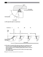
Figure 33. Turning cuts and associated insert geometries for forming and shearing of a chip.
[Courtesy of Sandvik Coromant]
.
Turning and Chip-breaking Technology
this being a somewhat shorter length than that of the
‘shiny’ underside at the tool/chip interface.
Many theories have been given for the actual ‘cause
and eect’ of preliminary chip formation which is
schematically illustrated Fig. 33d – ‘A’- one such, be-
ing that any formation is related to the cutting speed.
A large insert rake angle normally means that there is
less tendency for chip curling through a larger radius,
but it will have lower cutting forces. In Fig. 33d – ‘B’ ,
is depicted a somewhat ‘idealised’ view of the actual
cutting process, which can be expressed via the simple
relationship of ‘λ’ and ∆X/∆Y.
NB:
In this schematic representation: ‘h
1
’ represents
D
OC
and, ‘ϕ’ is the ‘shear plane angle’.
When utilising CNC machine tools and in particu-
lar turning centres, a major problem is the variety of
continuous chip forms created and the large quantity
and volume of swarf
29
produced. e manner to which
swarf aects machining operations depends upon the
operating conditions, but fundamentally there are sev-
eral requirements in any form of swarf control, these
are:
•
e swarf must ow freely away from the cutting
zone, without impairing the cutting action’s e-
ciency,
•
Swarf must be of convenient size and shape to fa-
cilitate handling manually, or in swarf conveyors
(i.e. if tted), together with any future large-volume
storage, then transportation and subsequent dis-
posal,
•
Any swarf should drop away into the machine’s
swarf tray, without snarling around, the workpiece,
tool, or interfering with other functions such as:
automatic tool-changing magazine/turret, in-situ
touch-trigger inspection probes, component load-
29 Individual chips when in any great volume are generally
termed swarf. It is important to be able to manage this swarf
volume and, satisfactory chip control can be determined by
‘Lang’s chip-packing ratio’ , this being denoted by the letter
‘R’ , in the following manner:
R = Chip volume (mm
3
)/Equivalent volume of uncut work-
piece material (mm
3
)
NB: ‘R’ ranges from values of 3-to-10, where an R-value of
4 gives satisfactory chip-breaking control, producing neatly
curled ‘6 and 9-shaped’ chips.
ing equipment, such as overhead gantries, or dedi-
cated robotic loading devices.
In terms of priority for these swarf control factors, pos-
sibly the most important one is that the swarf should
ow smoothly away from the cutting area, as with the
latest chip-breakers tted to today’s cutting inserts,
chips can be readily broken and controlled
30
, this will
be theme of the following section.
.. The Principles of Chip-Breaking
In machining, the cutting edge’s primary function is
to remove stock from the workpiece. Whether this
is achieved by forming a continuous chip, or by the
ow of elemental chips will depend upon several fac-
tors, including the properties of the workpiece mate-
rial, cutting data employed and coolant type and its
delivery. e terms ‘long-chipping’ and ‘short-chipping’
are utilised when considering the materials to be ma-
chined. Short-chipping materials such as most brasses
and cast irons, do not present a chip-breaking problem
for swarf disposal, so this section will concentrate on
the long-chipping workpiece materials, with particu-
lar focus on ‘steel family’ grades. Steels are produced
in a wide variety of specications and this allows
their properties to be ‘tailored’ to the specic indus-
trial applications. In addition, these steels methods of
primary processing, such as: casting, forging, rolling,
forming and sintering, together with the type of subse-
quent heat treatment, creates still further metallurgical
variations that may have an even greater inuence on
the workpiece’s chip-breaking ability. e workpiece’s
strength and hardness values describe the individual
material’s character to some extent, but it should be
borne in mind that it is the chip’s mechanical strength
that determines whether it can be broken with ease.
No absolute correlation exists between a steel com-
30 Today, many high-volume manufacturing companies have re-
alised the benet of the value of clean and briquetted swarf,
as opposed to oily scrap swarf, which sells at just ‘fractions’
of this value. At present, briquetted and cleaned aluminium
swarf can be sold for approaching £1,000/tonne, moreover,
the coolant/oil can be reclaimed, further driving down the
overall machining costs. For other non-ferrous ‘pure’ metals
and others, such as copper alloys and brasses, the economic
savings are even greater.
Chapter