Báo cáo hóa học: " Research Article Resource Sharing via Planed Relay for HWN∗" pptx
Bạn đang xem bản rút gọn của tài liệu. Xem và tải ngay bản đầy đủ của tài liệu tại đây (994.85 KB, 14 trang )
Hindawi Publishing Corporation
EURASIP Journal on Advances in Signal Processing
Volume 2008, Article ID 793126, 14 pages
doi:10.1155/2008/793126
Research Article
Resource Sharing via Planed Relay for HWN
∗
Chong Shen, Susan Rea, and Dirk Pesch
Centre for Adaptive Wireless Systems, Department of Electronic Engineering, Cork Institute of Technology, Ireland
Correspondence should be addressed to Chong Shen,
Received 23 October 2007; Revised 22 February 2008; Accepted 1 April 2008
Recommended by J. Wang
We present an improved version of adaptive distributed cross-layer routing algorithm (ADCR) for hybrid wireless network with
dedicated relay stations (HWN
∗
) in this paper. A mobile terminal (MT) may borrow radio resources that are available thousands
mile away via secure multihop RNs, where RNs are placed at pre-engineered locations in the network. In rural places such as
mountain areas, an MT may also communicate with the core network, when intermediate MTs act as relay node with mobility. To
address cross-layer network layers routing issues, the cascaded ADCR establishes routing paths across MTs, RNs, and cellular base
stations (BSs) and provides appropriate quality of service (QoS). We verify the routing performance benefits of HWN
∗
over other
networks by intensive simulation.
Copyright © 2008 Chong Shen et al. This is an open access article distributed under the Creative Commons Attribution License,
which permits unrestricted use, distribution, and reproduction in any medium, provided the original work is properly cited.
1. INTRODUCTION
Time Division Multiple Access (TDMA)-based digital cel-
lular standard global system for mobile (GSM) was first
deployed in 1990 with a new 900-MHz band. However, due
to uneven nature of the time-varying spatial distribution [1],
network performance metrics are not sufficient for today’s
wireless network where more ad hoc features are being
introduced.
To e ffectively manage problems stated above, we propose
to combine the advantages of different networks so that the
Mobile Terminal (MT) can utilise an optimised MANET,
the base-station-oriented network (BSON) and the relay
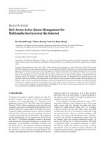
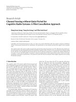
services. Figure 1 presents hybrid wireless network with relay
nodes (HWN
∗
), the relay nodes (RNs) of core network
compose a mesh-like structure connected to the internet
protocol (IP) networks through RN gateways, while base
stations (BSs) are connected to the IP networks via switches.
In rural places without infrastructure support as indicated
in Figure 1, two MTs may communicate directly, or through
intermediate MTs. When an MT transmits packets to a BS
through RNs, the RNs extend the signalling coverage of
BSON thus we can expect an enhanced resource-sharing
performance.
An adaptive distributed cross-layer routing (ADCR)
algorithm is proposed for HWN
∗
based on [2] using the
minimal number of hops and considering routing model
dynamic switching to reduce latency, preserve communica-
tions, deliver good overall throughput/per node throughput,
and extend the HWN
∗
coverage. A cross-layer network
design [3] that seeks to enhance the system performance by
jointly designing MAC and NETWORK layers is adopted.
We analyse in design stage the theoretical cellular network
media access capacity, multihop traffic relaying issues, and
inter network traffichandovers[4]. The cascaded ADCR
then includes three subpacket transmission modes labeled
as one-hop ad-hoc transmission (OHAHT) for point-to-
point ad hoc direct communication, multihop combined
transmission (MHCT) for radio resource relaying using fixed
RNs or MTs, and cellular transmission (CT) for traditional
cellular service. In rural places without infrastructure RN
support, the MHCT transmission mode can be implemented
on selforganised ad hoc nodes for supporting multihop
communication as long as: (i) The resource of relaying MTs
is contention-free, (ii) the migration range of relaying MTs
is limited, and (iii) the speed changes of relaying MTs in
sampling times have limited influence on routing.
The paper begins with a heterogenous wireless networks
RN incorporation discussion, including the comparison
work between proposed HWN
∗
framework stage I and
HWN
∗
framework stage II. We present two pre-engineered
RNs positioning algorithms in Section 3.InSection 4,we
2 EURASIP Journal on Advances in Signal Processing
MT
MT
MT
MT
MT
MT
MT
MT
MT
MT
MT
MT
MT
MT
MT
MT
MT
MT
MT
MT
MT
MT
MT
MT
MT
MT
MT
MT
MT
MT
MT
MT
MT
MT
MT
Core network
connected to
IP network
Rural place
Rural place
Rural place
IP network
Relay BS connection
Relay relay connection
BS BS connection
MT MT connection
Mobile terminal
Relay node
Base station
Figure 1: The hybrid wireless network with fixed relay stations.
discuss three traffic transmission modes with emphasis on
MHCT mode in copy with newly included packet relaying
environment. The ADCR performance of the HWN
∗
under
various scenarios is evaluated in Section 5 to address network
capacity, per MT throughput, access speed, and end-to-end
delay. Finally in Section 6, conclusions are made with future
research outlook.
2. HETEROGENOUS WIRELESS NETWORKS
The further balance of radio resource in heterogeneous
networks or hybrid wireless networks requires assistant
equipment functioned-like internetwork switcher, thus we
introduced a new node structure (RN), and further divided
it into heterogeneous RN that uses different radio access tech-
nology (RAT) with common or different sets of transmission
resources for its links and homogeneous relay node that uses
the same radio access technology and mode in a common
set of transmission resources for its entire links. For example,
the IST-WINNER [5] project proposes to share the same RAT
with BSs, RNs, and MTs to realise a dynamic spectrum usage.
Multiple noninterfering relay frequencies operate in parallel
through the use of intelligent radios. The spectrum where
an RN operates can be leased for a limited time depending
on network status. The spectrum on which it is operating
is reclaimed when network performance improves. Two RNs
operating on noninterfering spectrums form a network relay
link with multiple orthogonal bands. Multiple nodes within
range of each other may also transmit simultaneously on
different channels without relying on a media access protocol
or distributed scheduling algorithm to resolve contention.
Focus on different design objectives, the iCAR [6]is
derived from existing cellular networks and enables the
network to achieve theoretical capacity through adaptive
traffic load balancing. The SOPRANO [7] is a scalable
architecture that assumes the use of asynchronous code-
division multiple access (CDMA) with spreading codes to
support high-data-rate internet and multimedia traffic. It is
similar to iCAR other than IP network support and cross
network connection methods. We summarise in Tab le 1
the main research improvements from the HWN
∗
stage I
[4] to the HWN
∗
stage II. The comparison between the
Chong Shen et al. 3
Table 1: Research improvement of HWN
∗
framework stage II.
project
HWN
∗
framework stage I HWN
∗
framework stage II
Main objectives
Incorporate a MANET to increase system capacity
while realising differentiated QoS services
Stage I + Investigation on places without infrastruc-
ture support
Basic infrastructure
BSON, BSON with RN, MANET with RN
BSON, BSON with RN, MANET with RN and
MANET
Routing issues
BS switch and RN assisted trafficdiversion
Cascaded and distributed routing with three trans-
mission modes
Mode movement issues
Attractorpointsmodel
Costudy of user movement model and RN placement
algorithm
Congestion control
QoS-based session congestion control algorithm QoS-based session congestion control algorithm
RN positioning scheme
Fix point RN positioning RN positioning considering node movement pattern
Load balance
QoS-based multihop load balancing QoS-based multihop load balancing
Call admission
The BS coordinated admission Distributed session admission algorithm
iCar, multipower architecture for cellular network (MuPAC),
hybrid wireless network (HWN) without RN support,
WINNER, SOPRANO, and MCN can be found in [4, 8]with
the identification of technologies used.
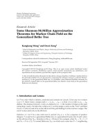
Consider a cellular handover scenario in Figure 2 where
MT A is currently connected to MT B and is moving out
of Cell 1 into Cell 6. A request for a BS handover will be
sent as soon as the power level by MT A goes below a
certain threshold (trajectory indicated by red dotted line).
A successful handover will take place within a few hundred
milliseconds depending on speed before the received power
from BSs reaches an unacceptable level. When MT A
arrives in Cell 6, if the congestion persists in cell 6 for a
period of time during which the MT moves farther away
from the other neighbouring cell border, thus causing the
received power level from BS A to fall below the acceptable
level, handover will fail and the call will be permanently
terminated.
However, in MHCT mode of HWN
∗
, the data session
does not have to be dropped even though the congestion
in Cell 6 persists. For example, when MT A moves into
the congested Cell 6, apart from trying cellular connections,
it also associates itself with an RN using either ad hoc
frequency or cellular frequency, then the RN may continue
transmission with any BS via the multihop relaying structure
and the relaying path can be also extended to the area
with no cellular coverage. For example, the routing path
for an MT in rural place can be even from MT
→ MTs
→ core network; and the corresponding frequencies used
can be ad hoc frequency
→ ad hoc frequencies → either ad
hoc frequency or cellular frequency. In addition, OHAHT
of point-to-point ad hoc communications can be another
routing mechanism option to further balance trafficload.
The simulation results presented in [4]havealreadyproven
that inter network traffic management can significantly
improve the grade of service, reduce the traffic blocking
probability, while maintaining the QoS.
The relay concept extends service range, optimises
cell capacity, minimises transmit power, covers shadowed
areas, supports inter network load balancing, and supports
MANET routing. Theoretically, both the HWN
∗
system
capacity and the transport capacity per MT, when compared
to a cellular network, should be improved because the RNs
provide relay capability as the substitution of a poor-quality
single-hop wireless link with a better-quality link being
encouraged whenever possible. Also a higher end-to-end
data rate could be obtained if an MT had two simultaneously
communicating interfaces.
Using three scaling approaches, we can implement
network/simulation dimensioning and estimate how many
RNs should be deployed when the number of MTs changes.
The three parameters are the number of RNs m, the number
of MTs n, and the system capacity C. The asymptotic scaling
for the per user throughput as n becomes large is
m
≤
n
log n
. (1)
The per user throughput is of the order C/
n/ logn and
can be realised by allowing only ad hoc communications
which do not necessarily need RN support, when
n
log n
≤ m ≤
n
log n
. (2)
The order for the per user throughput is Cm/n, therefore
the total additional bandwidth provided by m RNs is
effectively shared among n MTs. Finally, when
n
log n
≤ m,(3)
the order of the per user throughput is only C/ log n
which implies that further investments in relay nodes will
not lead to an improvement in throughput and bandwidth
optimisation.
3. RN-PLACEMENT ALGORITHMS
We explore the relay node placement and HWN
∗
ini-
tialisation problem in this section. The network spectral
efficiency was taken by [9] as the objective to optimise RN
positioning. The paper made the assumption that the quality
4 EURASIP Journal on Advances in Signal Processing
MT A
MT B
MT A
Relay node
with radio tower
Base station
with radio tower
1
Cell 1
Cell 2
Cell 3
Cell 5
Cell 4
Cell 6
Cellular interface
MANET interfaces
Base station
with radio tower
6
Figure 2: Multihop combined transmission example of cellular resource relaying using fixed RNs.
on the links connecting BS ↔ RN is always better than the
link between RN
↔ RN. This assumption can be satisfied
by establishing line-of-sight (LOS) links between BS and
RN or by designing links that enhance the antenna gains.
However, the solution imposes extra difficulty on network
planning by complicating transceiver design. In this section,
two RN positioning algorithms are proposed, which are
packing-based RN placement and heuristic RN placement
considering user movement behaviours. The algorithms
implementation is to use a minimum number of RNs that
enable the relaying of maximum traffic under the media
contention from both cellular and ad hoc perspectives.
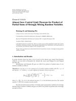
It is well known from planar geometry that to cover a
two-dimensional district with equal-sized circles, the best
possible packing solution can be obtained by surrounding
each circle by six circles as shown in Figure 3 left. But to
have connections between the RNs, an overlap between relay
cells is required. We therefore consider a situation where the
location of the RNs is centered with maximum coverage. The
deployments shown in Figure 3 (left side) are two examples
of such pre-engineered approach with a number of RNs in
the HWN
∗
. The first deployment tries to cover the entire
area while the second one tries to cover densely populated
regions.
Heuristic RN placement that we devised has a straight-
forward design philosophy based on two most important
factors, which are user movement behaviour and bandwidth
utilisation. By imposing such a plan, we can improve the
availability of MTs at disadvantaged locations and enlarge
network dimensioning possibility. It is first assumed that
RNs can acquire SIR information via local estimation
according to the distance. The RN positioning is formulated
as a constrained optimisation problem, of which the goal
is to maximise the overall network throughput and per
node throughput so that majority MTs are better served
with guaranteed QoS. The attractor points mobility model
deployed on MTs uses macro- and microcontrols to improve
user movement experiences, it may be not practical to
calculate each MT’s trajectory, but probabilities of user
reaching a set of frequently visited points can be useful.
Coincidentally, the hottest areas are places where most
media contention happens, and RN can be located in these
points to mitigate the contention. The next step of the
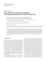
heuristic algorithm is to decide the number of RNs needed
in solving bandwidth contenting with guaranteed QoS. As
shown in Figure 4, after getting traffic load information, the
RN number used for further simulation studies is actually
estimated through network dimensioning analysis discussed
Chong Shen et al. 5
Packing based RN placement
For entire area For populated place
Calculated RN places
Calculated RN places
Relay node
MT
MT
MT
MT
MT
MT
MT
MT
MT
MT
MT
MT MT
MT
MT
MT
MT
MT
MT
MT
MT
MT
MT
MT
MT
MT
MT
MT
MT
MT
MT
MT
MT
MT MT
MT
MT
MT
MT
MT
MT
MT
MT
MT
MTMT
MT
MT
MT
MT
MT
MT
MT
MT
Heuristic based RN placement
MT movement
MT movement
Calculated RN places
MT movement
Relay node
Figure 3: Packing-based RN placement and heuristic RN placement.
in Section 2. The migration experiments are carried out to
produce a set of candidate points. A hard distant limit δ is
introduced and if distance between one candidate point and
any BS is smaller or equal to δ, this point will be eliminated
from final list.
The HWN
∗
, after RN placement, is then formed in two
stages, which are serving RN, BS association stage, and route
identification stage. More details on network formation can
be found in [4].
4. ADAPTIVE DISTRIBUTED CROSS-LAYER ROUTING
The QoS flows can consume all the bandwidth on certain
links, thus creating congestion for, or even starvation of, best
effort sessions. Statically, partitioning the link resources can
result in low network throughput if the trafficmixchanges
over time. Thus, a mechanism that dynamically distributes
link resources across traffic classes based on the current load
conditions in each traffic class is critical for performance.
By proposing a cascaded adaptive distributed cross-layer
routing (ADCR) for HWN
∗
, we discourage applications
from using any route that is heavily loaded with low-priority
traffic. Traditional routing strategies that use global state
information are not considered. Problems associated with
maintaining global state information and the staleness of
such information are avoided by having individual MTs
infer the network states based on route discovery statistics
collected locally, and perform traffic routing using this
localised view of the network QoS state. Each application,
categorised by service class with the choice of three possible
transmission modes, maintains a set of candidate paths to
each possible destination and routes flows along these paths.
The selection of the candidate paths is a key issue in localised
routing and has a considerable impact on how the ADCR
performs. The high-priority traffic is given high priority in
accessing comparatively expensive cellular resource, while
low-priority traffic tries to access low-cost ad hoc resource.
Per MT bandwidth is used as the only metric for route local
statistics collection since it is one of the most important
metrics in QoS routing, furthermore, important metrics
such as end-to-end delay, jitter can be expressed as a function
of the bandwidth.
We div id e tr affic sessions into simple service classes
which are high-profile users (HPUs), normal-profile users
(NPUs), and low-profile users (LPUs). Principally, HPUs
get the best QoS, next comes NPUs with smaller medium
access opportunities. LPUs are a best-effort class with unused
medium resources by other classes. HPUs have the highest
access priority in any communication modes of HWN
∗
,and
traffic admission of NPUs and LPUs has to consider ongoing
HPUs sessions. The NPUs are configured to have a higher
probability than LPUs in terms of resource acquisition and
this probability is decided by an association level (AL) set.
In case of network congestion, CT mode may temporarily
become unavailable to NPUs when HPUs are not fully
accommodated, while LPUs sessions may be only granted
MHCT and OHAHT mode access to mitigate network
congestion, reduce transmission delay, and improve per MT
throughput. More details of resource acquisition, QoS-based
media access control, traffic class coordination, and traffic
class association were explained in [4].
The RN has the right to reserve QoS-guaranteed free
channels for packet transmission and it maintains a status
table that refers to other RNs and it provides information
on changing busy conditions or relay failure. The purpose of
bandwidth reservation is to let RNs that receive the relaying
6 EURASIP Journal on Advances in Signal Processing
Network initialisation
MTs start moving using proposed
mobility algorithm
In sampling time, record MTs
positions
Record all MT associated BSs
positions
Stop moving?
Stop
Ye s
No
Figure 4: Flowchart of heuristic RN placement.
discovery command check if they can provide the bandwidth
required for the connection.
To avoid having higher traffic classes being influenced
by lower traffic classes in terms of queueing delay, we place
a waiting time limitation on each traffic class and force
starving packet switch transmission model [4]. A trafficflow
maintains two queues: a slot queue and a packet queue,
and we decouple slot queue for traffic class identification
from packet queue for transmission. Start and finish tags
are associated with slots but not packets. When a packet
arrives for a flow, it gets added to the packet queue, and
a new slot is added to the slot queue. Corresponding start
and finish tags are assigned to the new slot. The way
to raise priority in slot queue is that the packets related
to a high profile have shorter backoff time to increase
the probability of early medium access. As for the status
table maintenance, information flooding is restricted to a
limited scope. Once a positive acknowledgment message is
confirmed by requesting RN, the relay paths will not be
changed unless resource contention happens. Given the fact
that maintaining global RNs channel status in each RN slows
down RN response time, we only require each RN update
neighbouring RNs’ information, periodically.
The cascaded ADCR scheme includes three subpacket
transmission models, which are the OHAHT, the MHCT,
and the CT as illustrated in Figure 5. The communication
commands are defined as
(i) ACK/ACCEPT/REJECT/REJHO for the message-
delivery acknowledgment, packet acceptance, packet
rejection, and after-rejection handover request.
(ii) SEARCH/SETUP/DATA/BREAK for destination
node finding, new connection establishment, packet
delivery, and connection teardown.
(iii) MOS for MT to choose adaptive transmission mode.
(iv) FAIL used to acknowledge any failure on RN or MT.
(v) LREQ to request a label during the routing, The
label is a short, fixed-length identifier. Multiple labels
can identify a path or connection from the source
MT to the destination MT. The structure of a
label message contains flag, flow, cost, traffic class,
mobility information, and time tO lIVE (TTL).
(vi) LREP to request a label replay during the label
routing in MHCT model.
Time-sensitive multimedia applications have restrictions
on end-to-end transmission delay, while FTP data transfers
need a minimum guarantee on packet losses. The ADCR
should therefore consider differentiated QoS issues while
guaranteeing HPUs that agree to pay more than NPUs
and LPUs. However, due to the high priority of premium
traffic, the global network behaviour as a consequence of this
service class, including routing and scheduling of premium
packets, may impose significant influences on trafficofother
classes. These negative influences, which could degrade the
performance of low-priority classes with respect to some
important metrics such as the packet loss probability and
the packet delay, are often called the interclass effects.
To reduce the interclass effects, we proposed in [4]a
mechanism based on association level (AL) calculation for
load balancing of different service classes. The AL is a set
of parameters monitoring channel availabilities, an AL that
scores higher than the threshold means that the channels are
already occupied by ongoing sessions. The simulation results
demonstrated that the proposed mechanism distributes the
premium bandwidth requirements more efficiently, and the
traffic is better organised and balanced before routing.
Figure 5 also presents corresponding process of an MT’s
association with its serving BS and RN, and simplified ADCR
algorithm. As presented in script, if the source MT continues
transmitting directly until the SIR falls to a certain level, the
traffic re-routing or handovers will be initiated. In rerouting,
the model selection priority for HPUs is CT > MHCT >
OHAHT, while priorities for NPUs and LPUs are MHCT >
CT > OHAHT and OHAHT > MHCT > CT, separately. Also,
inter- and intranetwork handover triggers are discussed in
paper [4].
4.1. One-hop ad-hoc transmission
In OHAHT, the requesting MT first broadcasts SEARCH
messages to every node in its transmission range including
its associated RN and BS. For example, MT A in Figure 5
broadcasts SEARCH messages, if the destination MT B is
within its transmission range and there is no ad hoc-based
media contention between MT A and MT B, MT B can
respond to MT A with an ACK message. Once MT A
confirms the acknowledgment, it starts a connection SETUP
session immediately.
Chong Shen et al. 7
BS & RN Association()
{
For N MTsinacellularcell,0<i<N;
SIR
i
= Received signal quality evaluation of MT i from the serving BS;
For N MTsinacellularcell,0<i<N;
TTL = 1;
/
∗
Receive neighbouring information from surrounding RNs
∗
/
For N MTs, 0 <i<N, M RNs, 0 <j<M;
SIR
ij
= Received signal quality evaluation of MT i from surrounding RNs;
Sort SIR
ij
in descending order from high SIR to Low SIR;
Associated RN = the RN with Max(SIR
ij
);
}
ADCR Routing()
{
DB(i) = Node i’s distance from serving BS;
DR(i) = Node i’s distance from serving RN;
/
∗
Identify which trafficclassthepacketbelongsto,HPU,NPUorLPU
∗
/
Tr affic Class Discovery ();
/
∗
Individual packet routing with three sub models, OHAHT, MHCT and CT
∗
/
One hop adhoc transmission();
Multi hop combined transmission();
Cellular transmission();
Node i is scheduled to initiated a packet transmission at time T(k);
switch(service class)
{
case HPU():
/
∗
Evaluate QoS requirement and urgency based on weighted calculations
∗
/
Evaluation();
/
∗
Check media access constraints for three transmission models
∗
/
Media check();
/
∗
Try to use the transmission models in order of CT, MHCT then OHAHT
∗
/
HPU routing();
break;
case NPU():
Evaluation();
Media check();
/
∗
Try to use the transmission models in order of MHCT, CT then OHAHT
∗
/
NPU routing();
break;
case LPU():
Evaluation();
Media check();
/
∗
Try to use the transmission models in order of OHAHT, MHCT then CT
∗
/
LPU routing();
break;
}
RN
MT A
BS
MT B
RN
MT A
BS
MT B
RN
MT A
BS
MT B
Search
Ack
Ack
Search
Ack
Search
Ack
Search
Search
Search
Ack
Accept
Ack & data
Setup
Data
One-hop ad hoc transmission
Search SearchSearch
Ack
Accept
Ack & data
Setup
Data
Setup
Data
Accept
Ack & data
Setup
Accept
Data
Ack & data
Multi-hop combined transmission
Search SearchSearch
Ack
Accept
Ack & data
Ack
Setup
Data
Setup
Accept
Data
Ack & data
Cellular transmission
Figure 5: Computerised ADCR algorithm and simplified transmission modes illustration.
4.2. Multihop combined transmission
The MHCT can involve RNs acting as intermediate nodes
for message relaying. Figure 5 shows the connection setup
process for communication between MT A and MT B via the
RN infrastructure. MT A first broadcasts SEARCH messages
to every node to find MT B. After the SEARCH session, MT A
may find that the cellular resources can be borrowed through
RNs by receiving three ACK messages from the serving BS of
MT B, RNs, and the MT B. The positive acknowledgment
requires MT B to send an ACK to its serving BS, then the
serving BS sends an ACK to the RN infrastructure and finally
the RNs feedback the ACK to MT A. Once the positive
ACK is confirmed, the MT A starts a connection SETUP
from MTA
→RN, then RN→BS,andfinallyBS→MTB.The
DATA-transmission process follows the same packet delivery
route, and further route discovery is prohibited to reduce the
signalling overhead.
The label routing concept [10] originated from ATM
network is introduced to MHCT mode since RN switching
provides faster packet forwarding than routing because its
operation is relatively simple. The label switching protocol
uses signalling protocol distribute labels and set up new
route after the path is computed by the routing module.
This requires that the path is pre-established with signalling
before it can be used. In reactive MHCT mode with frequent
topology changes on both sender and receiver, a high rate
of path setup and tear down signaling may occur. It simply
can not use separate signalling to set up a new route. Instead,
the path finding process dynamically initialised by the LREQ
packet carrying a unique label and flow information, where
low-path setup delay is guaranteed. The flow information
8 EURASIP Journal on Advances in Signal Processing
RN A
MT A
MT B
BS
RN B
RN C
RN D
RN E
RN F
MT B
BS
RN B
RN C
RN D
RN E
RN F
MT A
MT B
BS
RN B
RN C
RN D
RN E
RN F
MT A
MT B
RN B
RN C
RN D
RN E
RN F
RN A
RN A
RN A
BS
LREQ_MTA
MT A
LREQ_RNA
LREQ_RNA
LREQ_RNC
LREQ_RNC
LREQ_RNC
LREQ_RND
LREQ_RND
LREQ_RND
LREQ_RNE
LREQ_RNE
LREQ_RNE
LREQ_RNE
LREQ_RNF
LREQ_RNF
LREQ_RNB
LREQ_RNB
LREP_RND
LREP_RND
LREP_RND
LREP_RNA
LREP_RNA
LREP_RNA
LREP_RNE
LREP_RNE
LREP_RNE
LREP_RNE
LREP_RNB
LREP_RNB
S.RNA.235
S.RND.168 S.RNE.009 S.RNB.815
<Source, S.RNA.235>
<S.RNA.235, S.RND.168>
<S.RND.168, S.RNE.009>
<S.RNE.009, S.RNB.815>
<S.RNB.815, destination>
Transmission model formation with
6 RNs possibly involved
MT A and RNs send
label request message
RNs send
label reply message
Label based
path established
Figure 6: Label routing illustration.
contains source address and a flow number is chosen by the
source node since the default source address is assumed to be
unique.
In finding the destination MT, the source MT creates an
LREQ message in which the packet contains IDs, sequence
number, and service class of the source MT. This packet
also contains traffic flow information, a broadcast ID, and
a hop count that is initialised to zero. All RNs that receive
this message will increment the hop count. If an RN does
not have any information about the destination node, it will
record the neighbour’s ID where the first copy of LREQ is
from and send this LREQ to its neighbours. LREQs from the
same node with the same broadcast ID will not be processed
more than once. Figure 6 gives an example of label routing
in MHCT. In this example, there are eight nodes with duplex
connection link.
The MT A first creates an LREQ message and sends it
out to its associated RN. Figure 6 illustrates the propagation
of LREQ across the RNs and the reverse path at every RN.
The reverse path entry is created for the transmission of
the reserved label for this path. This label is embedded in
the label-reply message LREP. The reserve path entry will be
maintained long enough for the LREQ to traverse the path
and for RNs to send an LREP to the source MT. Once a path
is found in the relay structure, the source MT will check the
sequence number (SEQ) of the destination MT in the current
path in order to avoid old path information. It should be
at least as great as the value entry in the LREQ. Otherwise,
the existing path in the table will be discarded. If SEQ
≥
SEQ
LREQ
, it will also check in the current path whether the
QoS requested by the source MT has been satisfied. If not,
this request will be discarded. If the source MT still can
not find the destination MT B, MT A will increment the
hop count in the LREQ by one and then broadcast it to its
neighbors. Any duplicated LREQ with same source node ID
and same broadcast ID will be discarded. Normally relay-
based label routing should have a maximum hop count.
However, there is no energy constraints and node mobility
issues in our relay infrastructure, thus theoretically any hop
count threshold can be possible. We specify the hop count in
LREQ as not being larger than 10 as a simulation limitation
to avoid computation complexity and if the sender of an
LREQ does not receive the reply message, each node only
resends the LREQ once for each connection request.
The RN only creates an LREP with the total hop count of
this path if hop count, sequence number, and path QoS are all
acceptable, the new sequence number of the destination MT
is the largest one between SEQ and SEQ
LREQ
, the best QoS,
and a label from its label pool. Then this LREP will be sent
back to the source MT along the reverse path entry. The third
plot in Figure 6 shows the propagation of the LREP along the
reserve paths. Note that both RN C and RN F fail to send
the LREP due to hop count, sequence number or QoS issues.
The path between the source MT and the destination MT
is composed of multiple segments and all data packets are
relayed by these segments. Each segment is a real connection
between two nodes and labeled by the sending-side node
of the LREP in this segment. For example in the the path
Chong Shen et al. 9
Table 2: Characteristics of QoS differentiated users.
Low-profile user Normal-profile user High-profile user
Portion Voice 20% Web 10% Video 5% Voice 15% Web 8% Video 10% Voice 10% Web 7% Video 15%
Voice dwell/session time: 60 s/120 s Web dwell/session time: 120 s/trace Video dwell/session time: 120 s/240 s
MTA↔RNA↔RND↔RNE↔RNB↔MTB showed in the last
plot of Figure 6, RNs A, D, E, and B set up the labels of
the segments between A and D, D and E, and E and E,
respectively.MTAandRNA,MTB,RNB,anditsassociated
BS are the other two segments. Since the topology of the relay
structure is meshed, the source MT can receive more than
one LREP. There is a hop count field in the LREP. This field
records the total number of hops of the path. The source
MT will choose the smallest hop count from the LREPs in
the specific limited time. All LREPs that are received after
this time threshold will be ignored. And if some available
LREPs have the same hop count, the path that has the largest
destination sequence number, which means it is the latest
path, will be chosen.
The MHCT mode can be also implemented in multi-
hop ad hoc transmissions in copy with rural environment
without infrastructure node support. The basic mechanism
is almost the same except MT replaces fixed RN and acts as
traffic switching nodes. The source MT first tries to establish
a connection destination node. If there is no path which can
reach the destination node in its local label routing table,
or the mobility constrains of MT relaying are violated, the
source MT will initiate another path discovery until TTL
reaches.
4.3. Cellular transmission
The last plot in Figure 5 shows the connection setup of CT
model between MT A and MT B via cellular BSs. MT A
first broadcasts SEARCH messages to every node to find
MT B. After the SEARCH session, the MT A finds that it is
able to communicate with MT B directly via BSs, while the
connection can be setup through a virtual wireless backbone.
The positive acknowledgment of a connection requires MT
B to send an ACK to its serving BS, then the serving BS
informs the serving BS of MT A or the BS feedbacks the
ACK to MT B when both MT A and MT B share the same
serving BS. Once the positive ACK is confirmed, MT A starts
connection SETUP from MTA
→BS, then BS→BS,andfinally
BS
→MTB. The DATA transmission process follows the same
packet-switched delivery route. Dynamic channel allocation
can be realised in a distributed manner given that the channel
usage does not break the two-channel interference constrains
[11] which are cosite constraint where there are minimum
channel separations within a cell and non-cosite constraint
where minimum channel separation between two adjacent
BSs is kept.
5. SIMULATION
We present various schemes and results of the simulation
that have been implemented for the ADCR in this section.
The OMNET++ simulator [12] is used and we generalise
all video streaming as real-time services, while web services
are referred to as nonreal-time services. Ta ble 2 presents
the default QoS profile used consisting of 30%, 64 Kbps
streaming video, 45% general voice calls, and 25% nonreal-
time web services. The service request portion is distributed
and shared among HPUs, NPUs, and LPUs.
The MTs are randomly distributed in 13 regular hexag-
onal cells (1km length, 2.6km
2
)inan8km× 8 km grid.
The HWN
∗
attractor point mobility model (HPMM) [4]is
implemented. At the simulation start, an MT schedules an
ACK message to itself before it determines a new position.
After saving the messages, the MT sends a MOVE message to
the physical layer and reschedules the ACK to be delivered in
a move interval. This metropolitan environment consists of
n points which MTs will move towards. The mobility model
implementation provides an approach which influences user
mobility in a distributed manner with micro mobility,
instead of grouping MTs with macro mobility.
BS is placed in the centre of each cell, and from 0 to
1300 MTs are scattered in HWN
∗
. To ensure frequency reuse,
7 frequencies are allocated to each cell with 128 available
channels. MT travels from 0 to 80 km/h since a relative
speed higher than 160 km/h is not suitable for the 802.11
radio propagation model, which has limited compensation
for channel fading. A node can not continue relaying packet
if its speed changes to more than 10 km/h. The log-normal
standard deviation σ is set as 10 dB, shadowing correlation
distance χ
s
is set to 50 m, and the mean SIR value r
d
is set
to 17 dB. Default energy model provided by OMNET++ is
implemented, specifically, for a 250 m transmission range the
transmit power used is 0.282 W. Transmit power used for a
transmission range of d is proportional to d
4
[13].
5.1. HWN
∗
capacity analysis
The first experiment is to present two pre-engineered RN
positioning strategies’ influence on the HWN
∗
capacity
under various traffic input. The HWN
∗
network operations
are considered, including the process of RN & BS registra-
tion, traffic balancing, routing path discovery, transmission
mode selection, and data delivery.
When packing-based RN positioning scheme is imple-
mented in the HWN
∗
, per cell capacity is expected greater
than random RN placement HWN
∗
and normal cellular
network under any traffic input. This is because these MTs,
which are not serviced in a cell, can use the packed relay
path to access other media resources strategically. With
the traffic input being increased higher, packing RN-based
HWN
∗
achieves complete connectivity regardless of cellular
service penetration percentage. Figure 7 records per cell
capacity performance of three scenarios with trafficload
10 EURASIP Journal on Advances in Signal Processing
0.5
1.5
1
2
2.5
3
3.5
4
4.5
5
5.5
6
(Mbps)
0 200 400 600 800 1000
Packing based RN placement HWN
∗
Random RN HWN
∗
Cellular network
Simulated time (in seconds, 100 seconds initialisation time)
Figure 7: Average capacity comparison of packing RN HWN
∗
,
random RN HWN
∗
, and cellular network.
being increased. The capacities of both packing RN-based
HWN
∗
and random RN-based HWN
∗
go up till maxi-
mum throughput reaches around 5.6 Mbps and 4.7 Mbps,
respectively. As we can see from the trend of capacity lines,
when the traffic input grows higher, packing RN-based
HWN
∗
outperforms the random RN HWN
∗
in terms of
network fairness, and its maximum capacity gets close to
the theoretical gain with a more uniform communication
experience.
Using the same simulation parameters, we also compare
per-cell per-second capacity of heuristic placement RN
HWN
∗
, random placement RN HWN
∗
, and mobile ad hoc
network. The AODV module provided by OMNET++ has
been simulated to realise MANET routing. Figure 8 Presents
the result. Overall, heuristic RN placement has the highest
capacity followed by packing algorithm, random HWN
∗
,
cellular network, and MANET (also refer to Figure 7). The
extremely low capacity of the MANET is the results of high-
contention level, erratic connections, and AODV protocol
overhead. Heuristic RN-based HWN
∗
outperforms packing
RN HWN
∗
under any traffic input, which indicates more
traffic is adaptively routed. The maximum capacity of this
structure achieves 5.7 Mbps.
For packet delivery ratio in the HWN
∗
, the system
throughput (ST) is defined as the delivery ratio:
ST =
Total number of data received
Total number of data sent
100%. (4)
In this experiment, we only implement UDP traffic(with
no handshaking mechanism) on each MT instead of the
default QoS0-based traffic profile, and network operations
of the proposed HWN
∗
are simulated. The packets are sent
at constant bit rate (CBR) with a packet size of 1500 bytes
and the MTs are added from 0 to 500 gradually as an input
parameter to increase the offered load. Figure 9 shows the
impact of increased traffic on the packet delivery ratio. It
0.5
1.5
1
2
2.5
3
3.5
4
4.5
5
5.5
6
(Mbps)
0 200 400 600 800 1000
Heuristic RN placement HWN
∗
Random RN HWN
∗
Mobile ad hoc network
Simulated time (in seconds, 100 seconds initialisation time)
Figure 8: Average capacity comparison of heuristic RN HWN
∗
,
random RN HWN
∗
, and mobile ad hoc network.
40
50
45
55
60
65
70
75
80
85
90
95
100
System throughput (%)
0 100 200 300 400 500
Packing RN placement HWN
∗
Random RN HWN
∗
Cellular network
Offered traffic loads (MTs with CBR UDP packets)
Figure 9: Packing RN HWN
∗
,randomRNHWN
∗
, and cellular
network throughput versus offered load.
indicates under any traffic input, the ADCR with packing
based-RNs placement gives a higher throughput than the
HWN
∗
with random RN placement and pure cellular sys-
tem. The packet delivery ratio decreases when the UDP traffic
load increases, this is mainly due to the congestion. However,
packing RN-based HWN
∗
outperforms random RN HWN
∗
or TDMA network by 12% and 26%, respectively, when the
maximum traffic load is achieved.
In Figure 10, we present the throughput performance
for heuristic-based RN placement HWN
∗
with the ADCR,
random RN positioning HWN
∗
and MANET with the
AODV algorithm, respectively. The curve of heuristic RN
Chong Shen et al. 11
40
50
45
55
60
65
70
75
80
85
90
95
100
System throughput (%)
0 100 200 300 400 500
Heuristic RN placement HWN
∗
Random RN HWN
∗
Mobile ad hoc network
Offered traffic loads (MTs with CBR UDP packets)
Figure 10: Heuristic RN HWN
∗
,randomRNHWN
∗
, and MANET
throughput versus offered load.
HWN
∗
corresponds to a case where all the transmitted
packets are maximally received, which can be considered to
be an upper throughput bound on this proposed scheme.
One can see that the increase of trafficloaddoesnotaffect
too much of the scheme’ performance. Overall, heuristic
algorithm has the highest throughput followed by packing
RN HWN
∗
, random RN HWN
∗
,cellularnetwork,and
MANET (also refer to Figure 9). Furthermore, we notice
that MANET exhibits a jittering performance with very
low throughput under any traffic conditions. When the
maximum traffic load achieves, the heuristic-based RN
structure outperforms packing-based structure by 3%.
5.2. Packet transmission delay
The average packet transmission end-to-end delay of a traffic
flow should be directly proportional to the number of hops
traversed by the flow, and inversely proportional to the flow’s
end-to-end throughput, this is an interesting metric to study
as the HWN
∗
network itself has a complicated transmission
arrangements, which can be seen as hybrid trafficmigration
of MANET, cellular network, and enhanced packet relay
services. The average End-to-end Delay (AED) is defined as
AED
=
Total number of data received
Total delivery time
. (5)
Simplified WINNER and SOPRANO hybrid network
infrastructures are therefore simulated with traffic routing
functionality. The WINNER concept system realises packet
switch through cooperative relaying, and RN operates same
resource management functions as cellular BS. In decen-
tralised SOPRANO, route path calculation is exclusively
carried out in local MT. A minimum energy routing pro-
tocol, as recommended in [14], which maximally saves the
0.05
0.15
0.1
0.2
0.25
0.3
0.35
0.4
0.45
0.5
0.55
0.6
Average end to end delay (s)
0 5 10 15 20 25
Packing RN based HWN
∗
SOPRANO
WINNER
Offered trafficloads(erlangs)
Figure 11: Average end-to-end transmission delay of HWN
∗
,
WINNER, and SOPRANO.
transmission power, is simulated for SOPRANO. Figure 11
presents the average end-to-end delay versus quantised load
offered for three hybrid networks. There is a significant
improvement in the delay performance of HWN
∗
ADCR,
compared to the cooperative relaying of the WINNER and
the minimum energy routing of the SOPRANO. At 15
Erlangs average offered load, the corresponding average end-
to-end delays are 0.10, 0.21, and 0.033 seconds and the delay
in other systems is almost two or three times larger than the
HWN
∗
ADCR under any trafficload.TheADCRscheme
adaptively selects paths with better quality and prevents
wasting transmission time.
Figure 12 presents the end-to-end delay comparison
result between packing RN HWN
∗
with ADCR, heuristic
RN HWN
∗
ADCR and heuristic HWN
∗
ADCR + MHCT ad
hoc. Interestingly, the MHCT ad hoc mode does not bring
too much negative impact on system performance and the
position of RNs either does not marginally influent delay
performance.
Apart from RN placement plan, the number of relay
nodes is another practical parameter to affect the HWN
∗
sys-
tem performance. The packing-based RN placement HWN
∗
is chosen as the test scenario causes a random RN number to
cut off heuristic algorithm that may cause large transmission
delay in hot spot. Figure 13 presents delay performance of
fully loaded RN, two third RN loaded and one third RN
loaded scenarios under increasing trafficload.Itclearly
indicates that the delay is much less in fully loaded RN plan,
compared to the other two scenarios with less infrastructure
nodes. One can estimate that an increase of one RN reduces
end-to-end delay while improves HWN
∗
throughput at least
3% average in a small system domain including seven cellular
BSs [15]. However, excessive installation of RN may not
be a preferable approach because a tradeoff exists between
management cost and expected system performance.
12 EURASIP Journal on Advances in Signal Processing
Table 3: Success route acquire ratio comparison between different user classes.
HPUs NPUs LPUs Simple HWN
∗
5 Erlangs/cell 100.0% 100.0% 98.0% 98.5%
10 Erlangs/cell 98.1% 93.2% 91.9% 86.2%
15 Erlangs/cell 97.3% 87.0% 86.7% 77.7%
20 Erlangs/cell 96.1% 84.4% 82.5% 57.5%
25 Erlangs/cell 95.0% 77.1% 72.1% 45.1%
0.05
0.15
0.1
0.2
0.25
0.3
0.35
0.4
0.45
0.5
0.55
0.6
Average end to end delay (s)
0 5 10 15 20 25
Packing RN based HWN
∗
Heuristic HWN
∗
ADCR
Heuristic HWN
∗
ADCR + MHCT ad hoc
Offered trafficloads(erlangs)
Figure 12: Average end-to-end transmission of various HWN
∗
scenarios.
0.05
0.15
0.1
0.2
0.25
0.3
0.35
0.4
0.45
0.5
0.55
0.6
Average end to end delay (s)
0 5 10 15 20 25
Fully loaded packing HWN
∗
2/3 RN loaded packing HWN
∗
1/3 RN loaded packing HWN
∗
Offered trafficloads(erlangs)
Figure 13: Average end-to-end transmission under various RN
loads.
40
50
45
55
60
65
70
75
80
85
90
95
Success ratio (percents)
0 5 10 15 20 25
HWN
∗
with ADCR
HWN
∗
without ADCR
Offered trafficloads(erlangs)
Figure 14: Comparisons of success route acquire ratio between
HWN
∗
ADCR and HWN
∗
without ADCR.
5.3. QoS-based routing analysis
Experiments are conducted to verify that if the ADCR
meets the goal of providing QoS differentiation among
different users based on their class profile. To setup a
comparison benchmark, we simulated a simple HWN
∗
without any dedicated resource management and routing
algorithms. Each packet session in this network has the same
privileges when accessing the media resource. The arriving
packet sessions are accommodated on a first-come-first-
serve basis until all available channels have been occupied.
An MT terminates the routing process when it can not
find an alternative route. Figure 14 shows the route acquire
success ratio with traffic load being constantly increased. The
ADCR scheme has the most successful acquire ratio since
it always returns a path on-demand and the performance
improvement is marginal when the system is heavily loaded.
The simple routing algorithm in the HWN
∗
performs worse
than the ADCR due to its limitation on route selection and
lack of alternate paths.
Ta ble 3 presents the individual class successful path
acquiring probabilities against trafficloadsoffered for
Chong Shen et al. 13
40
50
45
55
60
65
70
75
80
85
90
95
Success ratio (percents)
0 5 10 15 20 25
HWN
∗
with ADCR + MHCT ad hoc
HWN
∗
with ADCR
Offered trafficloads(erlangs)
Figure 15: Comparisons of success route acquire ratio between
HWN
∗
ADCR and HWN
∗
ADCR + MHCT ad hoc.
different user classes. It can be seen that different results are
experienced by user applications in different service classes
and for unclassified users in the simple HWN
∗
.Underlow-
and medium-traffic intensities, the success rates are similar
among HPUs, NPUs, and LPUs, since sufficient routes
are available and LPUs are not largely affected by HPUs
and NPUs communications. However, in the high-traffic
intensity case, HPUs and NPUs applications encounter large
resource competition in the MAC layer, which consumes
a considerable fraction of the radio resource. This may
adversely affect the route finding performance of LPUs,
in particular when an HPU and NPU traffic hot spot
occurs, LPUs are pushed to use the ad hoc communications
modes, where the routing process are comparatively unstable
compared against the infrastructure-based modes.
An interesting scenario is also investigated where we
enable multihop ad hoc communication with MHCT soft
relay implementation. When considering route acquire ratio,
15% of the MTs is configured residing in places outside
infrastructure support, while the rest of MTs still migrates
using attractor point mobility model. Configuration files for
simulation such as user profiles and traffic input are kept the
same as the files used in previous QoS-based routing analysis.
Figure 15 presents the result comparison between HWN
∗
with ADCR, and HWN
∗
with ADCR + MHCT ad hoc.
Different levels of route acquire ratio degradation happen in
both scenarios. However, under maximum traffic input, the
HWN
∗
with ADCR + MHCT ad hoc system outperforms the
HWN
∗
ADCR without multihop ad hoc communication by
11%.
6. CONCLUSION
In this article, we have presented an overview of heteroge-
nous wireless networks with the comparison between the
HWN
∗
stage I and HWN
∗
stage II works. We have devised
a cascaded selforganising routing scheme, the ADCR, and
enabled the communication in rural places using multihop
ad hoc communication. The routing algorithm employs a
service class-based approach to discourage applications from
using any route that is heavily loaded with low-priority
traffic, with three subtransmission modes. Simulation results
demonstrate that the ADCR further balances radio resource,
reduces transmission delay, and potentially increases the
network capacity. The future work will address cross-layer
resource selfoptimisation issues in cooperative networks with
dedicated relay nodes.
REFERENCES
[1] R. Beck and H. Panzer, “Strategies for handover and dynamic
channel allocation in micro-cellular mobile radio systems,” in
Proceedings of the IEEE 39th Vehicular Technology Conference
(VTC ’89), vol. 1, pp. 178–185, San Francisco, Calif, USA, May
1989.
[2] C. Shen, S. Rea, and D. Pesch, “Adaptive cross-layer routing
for HWN with dedicated relay station,” in Proceedings of
the International Conference on Wireless Communications,
Networking and Mobile Computing (WiCOM ’06), pp. 1–5,
Wuhan, China, September 2006.
[3] E. Setton, T. Yoo, X. Zhu, A. Goldsmith, and B. Girod, “Cross-
layer design of ad hoc networks for real-time video streaming,”
IEEE Wireless Communications, vol. 12, no. 4, pp. 59–65, 2005.
[4] C. Shen, S. Rea, and D. Pesch, “HWN
∗
mobility management
considering QoS, optimization and cross layer issues,” Journal
of Communications Software and Systems, vol. 4, no. 3, 2007.
[5] WINNER, “D4.3: identification, definition and assessment
of cooperation schemes between RANs,” Final deliver-
able, IST-2003-507581 WINNER, June 2005, -
winner.org/.
[6] H. Y. Hsieh and R. Sivakumar, “Performance comparison
of cellular and multi-hop wireless networks: a quantitative
study,” in Proceedings of the ACM SIGMETRICS International
Conference on Measurement and Modeling of Computer Systems
(SIGMETRICS ’01), pp. 113–122, Cambridge, Mass, USA,
June 2001.
[7] C. Murthy and B. Manoj, Ad Hoc Wireless Networks: Architec-
tures and Protocols, Prentice-Hall, Englewood-Cliffs, NJ, USA,
2004.
[8] B.S.Manoj,K.J.Kumar,C.D.Frank,andC.S.R.Murthy,“On
the use of multiple hops in next generation wireless systems,”
Wireless Networks, vol. 12, no. 2, pp. 199–221, 2006.
[9] H. Hu and K. Yanikomeroglu, “Performance analysis of cel-
lular networks with digital fixed relays,” M.S. thesis, Carleton
University, Ottawa, Canada, May 2006.
[10] A. Acharya, A. Misra, and S. Bansal, “A label-switching packet
forwarding architecture for multi-hop wireless LANs,” in
Proceedings of the 5th ACM International Workshop on Wireless
Mobile Multimedia (WOWMOM ’02), pp. 33–40, Atlanta, Ga,
USA, September 2002.
[11] C. Shen, D. Pesch, and J. Irvine, “Distributed dynamic channel
allocation with fuzzy model selection,” in Proceedings of the
Information Technology and Telecommunications Conference
(ITT ’04), Limerick, Ireland, October 2004.
[12] “Omnet++ discrete event simulation system,” http://www
.omnetpp.org/.
[13] G. L. Stuber, Principles of Mobile Communications,Kluwer
Academic Publishers, Norwell, Mass, USA, 1996.
14 EURASIP Journal on Advances in Signal Processing
[14] A. N. Zadeh, B. Jabbari, R. Pickholtz, and B. Vojcic,
“Self-organizing packet radio ad hoc networks with overlay
(SOPRANO),” IEEE Communications Magazine, vol. 40, no. 6,
pp. 149–157, 2002.
[15] C. Shen, D. Pesch, and J. Irvine, “Autonomic TDD link
optimising using hybrid wireless network and genetic algo-
rithms,” in Proceedings of the 62nd IEEE Vehicular Technology
Conference (VTC ’05), vol. 1, pp. 262–266, Dallas, Tex, USA,
September 2005.