Báo cáo hóa học: "Research Article DFT-Based Channel Estimation with Symmetric Extension for OFDMA Systems" pot
Bạn đang xem bản rút gọn của tài liệu. Xem và tải ngay bản đầy đủ của tài liệu tại đây (768.21 KB, 8 trang )
Hindawi Publishing Corporation
EURASIP Journal on Wireless Communications and Networking
Volume 2009, Article ID 647130, 8 pages
doi:10.1155/2009/647130
Research Article
DFT-Based Channel Estimation with Symmetric
Extension for OFDMA Systems
Yi Wang,
1, 2
Lihua Li,
1, 2
Ping Zhang,
1, 2
and Zemin Liu
1, 2
1
Key Laboratory of Universal Wireless Communications, Beijing University of Posts and Telecommunication,
Ministry of Education, Beijing 100876, China
2
Wireless Technology Innovation Institute, Beijing University of Posts and Telecommunication, Beijing 100876, China
CorrespondenceshouldbeaddressedtoYiWang,
Received 31 July 2008; Revised 10 November 2008; Accepted 18 January 2009
Recommended by Yan Zhang
A novel partial frequency response channel estimator is proposed for OFDMA systems. First, the partial frequency response is
obtained by least square (LS) method. The conventional discrete Fourier transform (DFT) method will eliminate the noise in time
domain. However, after inverse discrete Fourier transform (IDFT) of partial frequency response, the channel impulse response
will leak to all taps. As the leakage power and noise are mixed up, the conventional method will not only eliminate the noise, but
also lose the useful leaked channel impulse response and result in mean square error (MSE) floor. In order to reduce MSE of the
conventional DFT estimator, we have proposed the novel symmetric extension method to reduce the leakage power. The estimates
of partial frequency response are extended symmetrically. After IDFT of the symmetric extended signal, the leakage power of
channel impulse response is self-cancelled efficiently. Then, the noise power can be eliminated with very small leakage power loss.
The computational complexity is very small, and the simulation results show that the accuracy of our estimator has increased
significantly compared with the conventional DFT-based channel estimator.
Copyright © 2009 Yi Wang et al. This is an open access article distributed under the Creative Commons Attribution License, which
permits unrestricted use, distribution, and reproduction in any medium, provided the original work is properly cited.
1. Introduction
The orthogonal frequency-division multiplexing (OFDM)
is an effective technique for combating multipath fading
and for high-bit-rate transmission over mobile wireless
channels. In OFDM system, the entire channel is divided into
many narrow subchannels, which are transmitted in parallel,
thereby increasing the symbol duration and reducing the ISI.
Channel estimation has been successfully used to
improve the performance of OFDM systems. It is crucial for
diversity combination, coherent detection, and space-time
coding. Various OFDM channel estimation schemes have
been proposed in literature. The LS or the linear minimum
mean square error (LMMSE) estimation was proposed in
[1]. Reference [2] also proposed a low-complexity LMMSE
estimation method by partitioning off channel covariance
matrix into some small matrices on the basis of coherent
bandwidth. However, these modified LMMSE methods still
have quite high-computational complexity for practical
implementation and require exact channel covariance matri-
ces. Reference [3] introduced additional DFT processing to
obtain the frequency response of LS-estimated channel. In
contrast to the frequency-domain estimation, the transform-
domain estimation method uses the time-domain properties
of channels. Since a channel impulse response is not longer
than the guard interval in OFDM system, the LS and the
LMMSE were modified in [4, 5] by limiting the number
of channel taps in time domain. References [6, 7] showed
the performance of various channel estimation methods
and yielded that the DFT-based estimation can achieve
significant performance benefits if the maximum channel
delay is known. References [8–11] improved upon this
idea by considering only the most significant channel taps.
Reference [12] further investigated how to eliminate the
noise on the insignificant taps by optimal threshold.
However, in many applications such as OFDMA system,
only the estimates of partial frequency response are available,
and the estimate of channel impulse response in time domain
2 EURASIP Journal on Wireless Communications and Networking
LS channel
estimation
H
LS
0
H
LS
1
.
.
.
H
LS
N
−1
N-point
IDFT
h
LS
0
.
.
.
h
LS
L
−1
0
.
.
.
0
N-point
DFT
H
DFT
0
.
.
.
H
DFT
N
−1
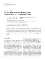
Figure 1: Block diagram of the conventional DFT-based channel
estimation.
cannot be obtained from the conventional DFT method.
After IDFT of partial frequency response, the channel
impulse response will leak to all taps in time domain. As
the noise and leakage power are mixed up, the conventional
DFT method will not only eliminate the noise, but also lose
the useful channel leakage power and result in MSE floor.
We have proposed the novel symmetric extension method
to reduce the leakage power. The mathematic expression of
the MSE of the conventional DFT estimator and the upper
bound of the MSE of our proposed estimator are derived in
this paper.
The rest of the paper is organized as follows. Section 2
describes the system model and briefly introduces the statis-
tics of mobile wireless channel. Section 3 proposes the novel
channel-estimation approach for OFDMA systems. Section 4
presents computer simulation results to demonstrate the
effectiveness of the proposed estimation approach. Finally,
conclusion is given in Section 5.
2. System and Channel Model
Consider an OFDMA system that has N subcarriers. The
data stream is modulated by inverse fast Fourier transform
(IFFT), and a guard interval is added for every OFDM
symbol to eliminate ISI caused by multipath fading channel.
At the receiver, with the ith OFDM symbol, the kth
subcarrier of the received signal is denoted as
Y
k,i
= H
k,i
· X
k,i
+ N
k,i
,(1)
where X
k,i
are the pilot subcarriers, for simplicity, it is
assumed that
|X
k,i
|=1, H
k,i
represents the channel
frequency response on the kth subcarrier. N
k,i
is the AWGN
with zero mean and variance of σ
2
.
The complex baseband representation of the mobile
wireless channel impulse response can be described by [13]
h(t, τ)
=
k
γ
k
(t)c
τ − τ
k
,(2)
where τ
k
is the delay of the kth path, γ
k
(t) is the correspond-
ing complex amplitude, and c(t) is the shaping pulse. For
OFDM systems with proper cyclic extension and timing, it
has been shown in [14] that the channel frequency response
can be expressed as
H
i,k
L−1
l=0
h
i,l
e
− j(2πkl/N)
,(3)
where h
i,l
h(iT
f
, l(T
s
/N)), T
f
and T
s
in the above
expression are the block length and the symbol duration,
respectively. In (3), h
i,l
,forl = 0, 1, , L − 1, are WSS
narrowband complex Gaussian processes. L is the number of
multipath taps. The average power of h
i,l
and Ldepends on
the delay profile and dispersion of the wireless channels.
3. Channel Estimation Based on
Symmetric Extension
3.1. Conventional DFT Method. For simplicity, the index i
is omitted in the following formulation. The LS channel
estimator is denoted as
H
LS
k
=
Y
k
X
k
= H
k
+
N
k
X
k
,0≤ k ≤ N − 1. (4)
After IFFT, the time-domain expression of
H
LS
k
is denoted as
h
LS
n
=
1
N
N−1
k=0
H
LS
k
e
j(2π/N)kn
=
1
N
N−1
k=0
H
k
+
N
k
X
k
e
j(2π/N)kn
= h
n
+ z
n
,
(5)
where h
n
is the channel impulse response on the nth path
z
n
= (1/N )
N−1
k
=0
(N
k
/X
k
)e
j(2π/N)kn
. Most mobile wireless
channels are characterized by discrete multipath arrivals, that
is, the magnitude of h
n
for most n is zeros or very small;
hence, these channel taps can be ignored. Assume L
GP
denote
the length of guard interval, then the maximum length of
nonzero h
n
is L
GP
,andh
n
= 0forL
CP
<n≤ N − 1. In the
conventional DFT method, in order to eliminate the noise,
h
DFT
n
=
⎧
⎨
⎩
h
LS
n
, n = 0, , L
GP
− 1,
0, n
= L
GP
, , N − 1.
(6)
The estimate of frequency response is denoted as
H
DFT
k
L−1
l=0
h
DFT
n
e
− j(2π/N)lk
. (7)
The basic block diagram of DFT-based estimation is shown
in Figure 1.
3.2. Partial Frequency Response by Conventional DFT. In
OFDMA system, as the pilot only occupies part of total
subcarriers, we can only get the estimates of partial frequency
response, which is denoted as
H
partial
k
=
H
LS
k+M
1
, k = 0, , M − 1, (8)
EURASIP Journal on Wireless Communications and Networking 3
where M is the length of partial frequency response. For
simplicity, we consider M
1
= 0 in this paper. However,
with only minor modification, the result discussed here is
applicable to any M
1
.TheM point IFFT result of
H
partial
k
is
denoted as
h
partial
n
=
1
M
M−1
k=0
H
partial
k
e
j(2πkn/M)
=
1
M
M−1
k=0
H
k
e
j(2πkn/M)
+
1
M
M−1
k=0
N
k
X
k
e
j(2πkn/M)
= h
partial
n
+ z
partial
n
,
(9)
where z
partial
n
= (1/M)
M−1
k
=0
(N
k
/X
k
)e
j(2πkn/M)
,andh
partial
n
is
denoted as
h
partial
n
=
1
M
M−1
k=0
H
k
e
j(2πkn/M)
=
1
M
M−1
k=0
L
−1
l=0
h
l
e
− j(2πkl/N)
e
j(2πkn/M)
=
1
M
L−1
l=0
h
l
C
partial
(n, l, M, N),
(10)
where C
partial
(n, l, M, N) =
M−1
k
=0
e
j(2πn/M−2πl/N)k
.From(10),
it can be seen that the channel impulse response h
n
will
leak to all taps of h
partial
n
. The conventional DFT method is
no longer applicable as h
partial
n
will be nonzero due to the
power leakage; the noise and leakage power are mixed up.
The elimination of noise will also cause the loss of useful
channel impulse response leakage.
It is assumed that each path is an independent zero-mean
complex Gaussian random process. The leakage power-to-
noise power ratio (LNR) on the nth tap in the conventional
DFT method can be denoted as
LNR
partial
n
=
E
h
partial
n
2
E
z
partial
n
2
=
L−1
l=0
σ
2
l
C
partial
(n, l, M, N)
2
Mσ
2
,
(11)
where σ
2
l
is the average power of the lth path. As the channel
power mainly focuses on the low-frequency band, in order to
eliminate the noise in high-frequency band, let L
partial
denote
the threshold, and the noise is eliminated by the conventional
DFT method,
g
partial
n
=
⎧
⎪
⎨
⎪
⎩
h
partial
n
,0≤n≤L
partial
− 1orM − L
partial
≤n≤M − 1,
0, L
partial
≤ n ≤ M − 1 − L
partial
.
(12)
The corresponding estimate of partial frequency response is
denoted as
U
partial
k
=
M−1
n=0
g
partial
n
e
− j(2πkn/M)
, k = 0, , M − 1. (13)
LS channel
estimation
H
partial
0
H
partial
1
.
.
.
H
partial
M
−1
M-point
IDFT
h
partial
0
.
.
.
h
partial
L
partial
−1
0
.
.
.
0
h
partial
M
−L
partial
h
partial
M
−1
M-point
DFT
U
partial
0
.
.
.
U
partial
M
−1
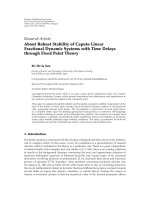
Figure 2: Block diagram of the partial frequency response DFT-
based channel estimation.
The basic block diagram of partial frequency response DFT-
based estimation is shown in Figure 2.
3.3. Partial Frequency Response Estimation by Symmetric
Extension Method. As H
k
,0 ≤ k ≤ N − 1 are the samples
of the continuous and periodic channel frequency response,
in time domain, the IFFT result of H
k
,0 ≤ k ≤ N − 1will
only concentrate on a few taps. However, the IFFT result of
the partial frequency response samples H
k
,0 ≤ k ≤ M − 1
will leak to all taps. This is because H
k
,0 ≤ k ≤ M − 1are
the samples of partial-frequency response, and after periodic
expansion, the continuity of the signal is severely destroyed.
If the leakage power is reduced significantly compared with
the noise power, the noise still can be eliminated efficiently
with very small loss of leakage power. Inspired by this,
in order to reduce the leakage power, we have proposed
the novel symmetric extension method to construct a new
sequence with better continuity.
H
partial
k
is extended with
symmetric signal of its own, and the symmetrically extended
signal is denoted as
H
symmetric
k
=
⎧
⎪
⎪
⎨
⎪
⎪
⎩
H
partial
k
,0≤ k ≤ M − 1,
H
partial
2M
−1−k
, M ≤ k ≤ 2M − 1.
(14)
After 2M point IFFT, the time-domain expression of
H
symmetric
k
is denoted as
h
symmetric
n
:
h
symmetric
n
=
1
2M
2M−1
k=0
H
symmetric
k
e
j(2πkn/2M)
=
1
2M
M−1
k=0
H
k
e
j(2πn/2M)k
+ e
j(2πn/2M)(2M−1−k)
+
1
2M
M−1
k=0
N
k
X
k
e
j(2πn/2M)k
+ e
j(2πn/2M)(2M−1−k)
=
h
symmetric
n
+ z
symmetric
n
,
(15)
4 EURASIP Journal on Wireless Communications and Networking
LS channel
estimation
H
partial
0
H
partial
1
.
.
.
H
partial
M
−1
Symmetric
extension
H
symmetric
0
H
symmetric
1
H
symmetric
2M
−1
2M-point
IDFT
h
symmetric
0
.
.
.
h
symmetric
L
symmetric
−1
0
.
.
.
0
h
symmetric
2M
−L
symmetric
h
symmetric
2M
−1
2M-point
DFT
G
symmetric
k
.
.
.
G
symmetric
2M
−1
Combination
U
symmetric
0
.
.
.
U
symmetric
M
−1
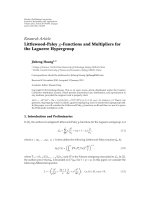
Figure 3: Block diagram of our proposed symmetric extension DFT-based channel estimation.
where z
symmetric
n
= (1/2M)
M−1
k=0
(N
k
/X
k
)(e
j(2πn/2M)k
+
e
j(2πn/2M)(2M−1−k)
), and h
symmetric
n
is denoted as
h
symmetric
n
=
1
2M
2M−1
k=0
H
symmetric
k
e
j(2πkn/2M)
=
1
2M
M−1
k=0
H
k
e
j(2πn/2M)k
+ e
j(2πn/2M)(2M−1−k)
=
1
2M
M−1
k=0
L
−1
l=0
h
l
e
− j(2πkl/N)
×
e
j(2πn/2M)k
+ e
j(2πn/2M)(2M−1−k)
=
1
2M
L−1
l=0
h
l
C
symmetric
(n, l, M, N),
(16)
where C
symmetric
(n, l, M, N) =
M−1
k=0
e
− j(2πl/N)k
(e
j(2πn/2M)k
+
e
j(2πn/2M)(2M−1−k)
).
The leakage power-to-noise power ratio (LNR) on the
nth tap can be denoted as
LNR
symmetric
n
=
E
h
symmetric
n
2
E
z
symmetric
n
2
=
L−1
l
=0
σ
2
l
C
symmetric
(n, l, M, N)
2
2Mσ
2
.
(17)
Let L
symmetric
denote the threshold. Using the con-
ventional DFT method, the noise and leakage power is
eliminated by
g
symmetric
n
=
⎧
⎪
⎪
⎪
⎪
⎨
⎪
⎪
⎪
⎪
⎩
h
symmetric
n
,0≤ n ≤ L
symmetric
− 1
or 2M
− L
symmetric
≤ n ≤ 2M − 1,
0, L
symmetric
≤ n ≤ 2M − 1 − L
symmetric
.
(18)
After 2M point FFT,
G
symmetric
k
=
2M−1
n=0
g
symmetric
n
e
− j(2πkn/2M)
, k = 0, ,2M − 1.
(19)
The corresponding estimate of partial frequency response is
denoted as
U
symmetric
k
=
G
symmetric
k
+ G
symmetric
2M
−1−k
2
, k
= 0, , M − 1.
(20)
The basic block diagram of our proposed symmetric exten-
sion DFT-based estimation is shown in Figure 3.
3.4. Performance Analysis. From (13), the MSE of the
conventional DFT method without symmetric extension is
written as
MSE
partial
=
1
M
E
M−1
k=0
U
partial
k
− H
k
2
. (21)
From (20), the MSE of our proposed estimator is
MSE
symmetric
=
1
M
E
M−1
k=0
U
symmetric
k
− H
k
2
. (22)
The estimation error of the conventional method is divided
into two parts. The first part is that when L
partial
≤ n ≤ M −
1 − L
partial
, the leakage power h
partial
n
is lost as it is forced to be
zero. The second part is that when n<L
partial
or n>M− 1 −
L
partial
, the error is caused by AWGN. The estimation error
can be written as
ERROR
partial
= h
partial
n
− g
partial
n
=
⎧
⎨
⎩
h
partial
n
, L
partial
≤ n ≤ M − 1 − L
partial
,
z
partial
n
, others.
(23)
EURASIP Journal on Wireless Communications and Networking 5
Similarly, the estimation error of our proposed method is
also divided into two parts. It can be written as
ERROR
symmetric
= h
symmetric
n
− g
symmetric
n
=
⎧
⎨
⎩
h
symmetric
n
, L
leakage
≤ n ≤ 2M − 1 − L
leakage
,
z
symmetric
n
, others.
(24)
According to the Parseval theorem, (21)canbewrittenas
MSE
partial
=
1
M
E
M−1
k=0
U
partial
k
− H
k
2
=
E
M−1
n=0
h
partial
n
− g
partial
n
2
=
E
M−1−L
partial
n=L
partial
h
partial
n
2
+ E
L
partial
−1
n=0
z
partial
n
2
+ E
M−1
n=M−L
leakage
z
partial
n
2
=
1
M
2
M
−1−L
partial
n=L
partial
L−1
l=0
σ
2
l
C
partial
(n, l, M, N)
2
+
L
partial
M
σ
2
+
L
partial
M
σ
2
=
1
M
2
M
−1−L
partial
n=L
partial
L−1
l=0
σ
2
l
C
partial
(n, l, M, N)
2
+
2L
partial
M
σ
2
.
(25)
From (24), (22)canberewrittenas
MSE
symmetric
=
1
M
E
M−1
k=0
U
symmetric
k
− H
k
2
=
1
M
E
M−1
k=0
G
symmetric
k
+ G
symmetric
2M
−1−k
2
− H
k
2
=
1
4M
E
M−1
k=0
G
symmetric
k
− H
k
+ G
symmetric
2M
−1−k
− H
k
2
≤
1
4M
2
· E
M−1
k=0
G
symmetric
k
−H
k
2
+
G
symmetric
2M
−1−k
−H
k
2
.
(26)
According to the Parseval theorem,
1
2M
E
M−1
k=0
G
symmetric
k
− H
k
2
+
G
symmetric
2M
−1−k
− H
k
2
=
E
2M−1
n=0
h
symmetric
n
− g
symmetric
n
2
=
E
2M−1−L
leakage
n=L
leakage
h
symmetric
n
2
+ E
L
leakage
−1
n=0
z
symmetric
n
2
+ E
2M−1
n=2M−L
leakage
z
symmetric
n
2
=
1
4M
2
2M
−1−L
leakage
n=L
leakage
L−1
l=0
σ
2
l
C
symmetric
(n, l, M, N)
2
+
L
leakage
M
σ
2
.
(27)
From (26), (27), the upper bound of the MSE of our
proposed estimator is
MSE
upper
symmetric
=
1
4M
2
2M
−1−L
leakage
n=L
leakage
L−1
l=0
σ
2
l
C
symmetric
(n, l, M, N)
2
+
L
leakage
M
σ
2
.
(28)
3.5. Estimator Complexity. The conventional DFT-based
channel estimator is very attractive for its good performance
and low complexity. Its main computation complexity is M
point IFFT and FFT. Our proposed symmetric extension
method also inherits the low complexity of the DFT estima-
tor, and its main computation complexity is 2M point IFFT
and FFT. As the complexity of FFT and IFFT is significantly
reduced nowadays, our proposed method can provide a good
tradeoff between performance and complexity.
4. Performance Results
We investigate the performance of our proposed estimator
through computer simulation. An OFDMA system with N
=
512 subcarriers is considered the guard interval L
GP
= 64.
The sampling rate is 7.68 MHz, and subcarrier frequency
space is 15 kHz. A six-path channel model is used. The power
profile is given by P
= [−3,0, − 2, − 6, − 8, − 10] dB,
and the delay profile after sampling is τ
= [0,2,4,12,18,38].
Each path is an independent zero-mean complex Gaussian
random process.
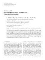
Figures 4 and 5 show the comparison of LNR between
the conventional DFT method and our proposed method. σ
2
is normalized to 1, and M is set to 16 and 64. It should be
6 EURASIP Journal on Wireless Communications and Networking
10
−6
10
−5
10
−4
10
−3
10
−2
10
−1
10
0
10
1
LNR
0 5 10 15 20 25 31
n
M
= 16 LNR
partial
M = 16 LNR
symmetric
Figure 4: LNR comparison when M = 16.
10
−6
10
−5
10
−4
10
−3
10
−2
10
−1
10
0
10
1
LNR
0 20 40 63 80 100 127
n
M
= 64 LNR
partial
M = 64 LNR
symmetric
Figure 5: LNR comparison when M = 64.
noted that the FFT length of the conventional DFT method
is M, while the FFT length of our proposed method is 2M due
to the symmetric extension. That is why the two curves have
different lengths. It is shown that LNR
partial
n
is much larger
than LNR
symmetric
n
. Compared with the conventional method,
the leakage power is significantly self-cancelled by symmetric
extension method.
Figure 6 shows the theoretical MSE of the conventional
DFT method when M
= 16. The MSE is calculated under
SNR
= 5 dB, 10 dB, and 20 dB, respectively. The MSE is large
when L
partial
is small, this is because although most noise can
be eliminated, the channel power h
partial
n
is also lost, and the
MSE is mainly caused by the loss of h
partial
n
. When L
partial
is
10
−2
10
−1
10
0
Theoretical MSE
123456 7
L
partial
SNR = 5dB
SNR
= 10 dB
SNR
= 20 dB
Figure 6: Theoretical MSE of conventional partial frequency
response DFT-based channel estimator.
10
−3
10
−2
10
−1
10
0
Theoretical MSE upper bound
12 4 6 8 10121415
L
symmetric
SNR = 5dB
SNR
= 10 dB
SNR
= 20 dB
Figure 7: Theoretical upper bound of the MSE of our proposed
symmetric extension DFT-based channel estimator.
large, although the loss of h
partial
n
is small, the noise cannot be
eliminated efficiently, and the MSE is mainly caused by the
noise.
Figure 7 shows the upper bound of the MSE of our
proposed method. Compared with Figure 6, the upper
bound of the MSE of our proposed method is smaller than
the MSE of the conventional DFT method. This is because
in our proposed method the channel leakage is significantly
reduced, and the elimination of noise will cause less channel
leakage power loss.
Figure 8 shows the MSE performance comparison of
different methods. M is set to 16. In the conventional DFT
EURASIP Journal on Wireless Communications and Networking 7
10
−4
10
−3
10
−2
10
−1
10
0
10
1
MSE
0 5 10 15 20 25 30 35 40
SNR (dB)
Conventional LS M
= 16
Conventional DFT M
= 16, L
partial
= 4
Conventional DFT M
= 16, L
partial
= 6
Symmetric extension M
= 16, L
symmetric
= 8
Symmetric extension M
= 16, L
symmetric
= 12
Figure 8: Comparing MSE performance with proposed estimator,
conventional DFT estimator, and LS estimator, when M
= 16,
L
partial
= 4.6, and L
symmetric
= 8.12.
10
−4
10
−3
10
−2
10
−1
10
0
10
1
MSE
0 5 10 15 20 25 30 35 40
SNR (dB)
Conventional LS M
= 64
Conventional DFT M
= 64, L
partial
= 16
Conventional DFT M
= 64, L
partial
= 24
Symmetric extension M
= 64, L
symmetric
= 32
Symmetric extension M
= 64, L
symmetric
= 48
Figure 9: Comparing MSE performance with proposed estimator,
conventional DFT estimator, and LS estimator, when M
= 64,
L
partial
= 16.24, and L
symmetric
= 32.48.
method, L
partial
is set to 4 and 6 as the FFT length of
our proposed method is doubled, and the corresponding
threshold L
symmetric
is set to 8 and 12. When SNR is low, both
the conventional DFT method and our proposed method
10
−3
10
−2
10
−1
10
0
BER
0 5 10 15 20 25 30
SNR (dB)
Conventional LS M
= 16
Conventional DFT M
= 16, L
partial
= 4
Conventional DFT M
= 16, L
partial
= 6
Symmetric extension M
= 16, L
symmetric
= 8
Symmetric extension M
= 16, L
symmetric
= 12
Figure 10: Comparing BER performance with proposed estimator,
conventional DFT estimator, and LS estimator, when M
= 16,
L
partial
= 4.6, and L
symmetric
= 8.12.
can reduce the MSE. However, when SNR is higher than
15 dB, there is an evident MSE floor larger than 10
−2
in the
conventional DFT method. While in our proposed method,
the MSE floor is eliminated efficiently. This is because when
SNR is low, the MSE is mainly caused by the noise, not
the loss of channel leakage power. When SNR is high, the
MSE is mainly caused by the leakage power loss instead. As
the leakage power is significantly reduced in our proposed
symmetric extension method, even when SNR is high,
the noise still can be eliminated at very small expense of
channel leakage power loss. Figure 8 also shows the effect
of threshold. It can be seen that when SNR is low, smaller
threshold has better MSE performance than larger threshold,
and when SNR is high, it has worse MSE performance. This
is because with the decrease of threshold, more noise can be
eliminated, but more channel leakage power will be lost, and
with the increase of threshold, less channel leakage power will
be lost, but less noise is eliminated.
Figure 9 shows the MSE performance when M is set to
64, L
partial
is set to 16 and 24, and L
symmetric
is 32 and 48.
The simulation result is similar to Figure 8. It proves that our
method is effective for different values of M.
Figure 10 shows the raw BER performance with different
channel estimation methods. Each subcarrier is modulated
by 16 QAM. M is set to 16, L
partial
= 4.6, and L
symmetric
=
8.12. The channel is equalized by zero-forcing algorithm.
It can be seen that the BER with the conventional DFT
channel estimator still encounters BER floor because of the
channel estimation errors. While in our proposed symmetric
extension method, as the accuracy of channel estimator
is significantly increased, the BER performance is also
improved.
8 EURASIP Journal on Wireless Communications and Networking
5. Conclusion
A simple DFT-based channel estimation method with sym-
metric extension is proposed in this paper. In order to
increase the estimation accuracy, the noise is eliminated in
time domain. As both the noise and the channel impulse
leakage power will be eliminated, we have proposed the novel
symmetric extension method to reduce the channel leakage
power. The noise can be efficiently eliminated with very small
loss of channel leakage power. The simulation results show
that, compared with the conventional DFT method, the MSE
of our proposed method is significantly reduced.
References
[1] O. Edfors, M. Sandell, J J. van de Beek, S. K. Wilson, and P.
O. Borjesson, “OFDM channel estimation by singular value
decomposition,” IEEE Transactions on Communications, vol.
46, no. 7, pp. 931–939, 1998.
[2] M. Noh, Y. Lee, and H. Park, “Low complexity LMMSE chan-
nel estimation for OFDM,” IEE Proceedings: Communications,
vol. 153, no. 5, pp. 645–650, 2006.
[3] Y. Zhao and A. Huang, “A novel channel estimation method
for OFDM mobile communication systems based on pilot
signals and transform-domain processing,” in Proceedings of
the 47th IEEE Vehicular Technology Conference (VTC ’97), vol.
3, pp. 2089–2093, Phoenix, Ariz, USA, May 1997.
[4] J J.vandeBeek,O.Edfors,M.Sandell,S.K.Wilson,andP.
O. Borjesson, “On channel estimation in OFDM systems,” in
Proceedings of the 45th IEEE Vehicular Technology Conference
(VTC ’95), vol. 2, pp. 815–819, Chicago, Ill, USA, July 1995.
[5] O. Edfors, M. Sandell, J J. van de Beek, S. K. Wilson, and P.
O. Borjesson, “Analysis of DFT-based channel estimators for
OFDM,” Wireless Personal Communications,vol.12,no.1,pp.
55–70, 2000.
[6] A. Dowler, A. Doufexi, and A. Nix, “Performance evaluation of
channel estimation techniques for a mobile fourth generation
wide area OFDM system,” in Proceedings of the 56th IEEE
Vehicular Technology Conference (VTC ’02), vol. 4, pp. 2036–
2040, Vancouver, Canada, September 2002.
[7] B. Yang, K. B. Letaief, R. S. Cheng, and Z. Cao, “Channel esti-
mation for OFDM transmission in multipath fading channels
based on parametric channel modeling,” IEEE Transactions on
Communications, vol. 49, no. 3, pp. 467–479, 2001.
[8] H. Minn and V. K. Bhargava, “An investigation into time-
domain approach for OFDM channel estimation,” IEEE
Transactions on Broadcasting, vol. 46, no. 4, pp. 240–248, 2000.
[9] M. R. Raghavendra and K. Giridhar, “Improving channel
estimation in OFDM systems for sparse multipath channels,”
IEEE Signal Processing Letters, vol. 12, no. 1, pp. 52–55, 2005.
[10] O. Simeone, Y. Bar-Ness, and U. Spagnolini, “Pilot-based
channel estimation for OFDM systems by tracking the delay-
subspace,” IEEE Transactions on Wireless Communications, vol.
3, no. 1, pp. 315–325, 2004.
[11] J. Oliver, R. Aravind, and K. M. M. Prabhu, “Sparse channel
estimation in OFDM systems by threshold-based pruning,”
Electronics Letters, vol. 44, no. 13, pp. 830–832, 2008.
[12] W. Yi, L. Lihua, Z. Ping, and L. Zemin, “Optimal threshold for
channel estimation in MIMO-OFDM system,” in Proceedings
of the IEEE International Conference on Communications
(ICC ’08), pp. 4376–4380, Beijing, China, May 2008.
[13] R. Steele, Mobile Radio Communications, IEEE Press, New
York, NY, USA, 1992.
[14] Y. Li, L. J. Cimini Jr., and N. R. Sollenberger, “Robust channel
estimation for OFDM systems with rapid dispersive fading
channels,” IEEE Transactions on Communications, vol. 46, no.
7, pp. 902–915, 1998.