Báo cáo hóa học: " Research Article On Traffic Load Distribution and Load Balancing in Dense Wireless Multihop Networks" pdf
Bạn đang xem bản rút gọn của tài liệu. Xem và tải ngay bản đầy đủ của tài liệu tại đây (1.84 MB, 15 trang )
Hindawi Publishing Corporation
EURASIP Journal on Wireless Communications and Networking
Volume 2007, Article ID 16932, 15 pages
doi:10.1155/2007/16932
Research Article
On Traffic Load Distribution and Load Balancing in
Dense Wireless Multihop Networks
Esa Hyyti
¨
a
1
and Jorma Virtamo
2
1
The Telecommunications Research Center Vienna (ftw.), Donau-City Strasse 1, 1220 Vienna, Austria
2
Networking Laboratory, Helsinki University of Technology, P.O. Box 3000, 02015 TKK, Finland
Received 29 September 2006; Accepted 13 March 2007
Recommended by Stavros Toumpis
We study the load balancing problem in a dense wireless multihop network, where a typical path consists of a large number of
hops, that is, the spatial scales of a typical distance between source and destination and mean distance between the neighboring
nodes are strongly separated. In this limit, we present a general framework for analyzing the traffic load resulting from a given set
of paths and traffic demands. We formulate the load balancing problem as a minmax problem and give two lower bounds for the
achievable minimal maximum traffic load. The framework is illustrated by considering the load balancing problem of uniformly
distributed traffic demands in a unit disk. For this special case, we derive efficient expressions for computing the resulting traffic
load for a given set of paths. By using these expressions, we are able to optimize a parameterized set of paths yielding a particularly
flat traffic load distribution which decreases the maximum traffic load in the network by 40% in comparison with the shortest-
path routing.
Copyright © 2007 E. Hyyti
¨
a and J. Virtamo. This is an open access article distributed under the Creative Commons Attribution
License, which permits unrestricted use, distribution, and reproduction in any medium, provided the original work is properly
cited.
1. INTRODUCTION
In a wireless multihop network, a typical path consists of
several hops and the intermediate nodes along a path act as
relays. Thus, in general, each node has two functions. First,
they can act as a source or a destination for some flow, that is,
the nodes can communicate with each other. Second, when
necessary, nodes have to relay packets belonging to the flows
between other nodes.
Several types of wireless multihop networks exist with
different unique characteristics. For example, wireless sensor
networks are networks designed to collect some information
from a given area and to deliver the information to one or
more sinks. Thus, for example, the traffic distribution in sen-
sor networks is typically highly asymmetric. Another exam-
ple of wireless multihop network is a wireless mesh network
consisting of both mobile and fixed wireless nodes and one
or more gateway nodes through which the users have access
to the Internet.
In this paper, we focus on studying a wireless multihop
network at the limit when the number of nodes is large.
At this limit, the network is often referred to as a mas-
sively dense network [1–3], or simply a dense network [4, 5].
In particular, we assume a strong separation in spatial scales
between the macroscopic level, corresponding to a distance
between the source and destination nodes, and the micro-
scopic level, corresponding to a typical distance between the
neighboring nodes. This assumption justifies modeling the
routes on the macroscopic scale as smooth geometric curves
as if the underlying network fabric formed a homogeneous
and isotropic (homogeneity and isotropicity are not crucial
but are assumed here to simplify the discussion) continuous
medium.
The microscopic scale corresponds to a single node and
its immediate neighbors. At this scale, the above assumptions
imply that only the direction in which a particular packet is
traversing is significant. In particular, considering one direc-
tion at a time, there exists a certain maximum flow of pack-
ets a given MAC protocol can support (packets per unit time
per unit length, “density of progress”). Generally, this maxi-
mal sustainable directed packet flow depends on the particu-
lar MAC protocol defining the scheduling rules and possible
coordination between the nodes. Determining the value of
this maximum is not a topic of this paper but is assumed to
be given (known characteristic constant of the medium). By
a simple time-sharing mechanism, this maximal value can be
shared between flows propagating in different directions. As
a result, the scalar or total flux (to be defined in Section 3)
2 EURASIP Journal on Wireless Communications and Networking
of packets is bounded by the given maximum, and the load
balancing task is to determine the paths in such a way that
the maximum flux is minimized.
Under the assumption of a dense multihop network, the
shortest paths (SPs) are at macroscopic-level straight line
segments [6]. Straight paths yield an optimal solution in
terms of mean delay when the traffic demands are low and
there are no queueing delays. However, they typically con-
centrate significantly more traffic in the centre of network
than elsewhere, and as the traffic load increases the packets
going through the centre of the network start to experience
queueing delays and eventually the system becomes unsta-
ble when the maximal sustainable scalar flux is exceeded.
Hence, the use of shortest paths limits the capacity of the
multihop network unnecessarily and our task is to minimize
the maximum packet flux in the network by a proper choice
of paths on the macroscopic scale. Note that in this paper,
we are not addressing details of any routing protocol. The
idea is, however, that when the destination of the packet is
known, also the optimal macroscopic path to the destination
is known. This path determines the direction to w hich the
packet should be forwarded, and this information is used at
the node level to make the actual forwarding decisions.
The main contributions of this paper are the formula-
tion of the traffic load and the corresponding load balancing
problem in general case, and the derivation of a computa-
tionally efficient expression for traffic load in a symmetric
case of a unit disk, which then allows us to optimize a pa-
rameterized family of paths. By traffic load we mean, roughly
speaking, the rate at which packets are transmitted in the
proximity of a given node, and the objective of load balanc-
ing is to find such paths that minimize the maximum traffic
load in the network. Formally, the spatial traffic load distri-
bution is defined as a scalar packet flux.
The organization of the paper is as follows. First, in
Section 2 related earlier work is briefly reviewed. Then, in
Section 3 we present the necessary mathematical fr amework,
that is, give a formal definition for different quantities at the
limit of (massively) dense network. In Section 4 we concen-
trate on deriving some bounds for the load balancing prob-
lem. The load balancing problem in wired networks is well
known and provides some insight into this problem. In par-
ticular, we give two lower bounds for the load balancing
problem, where both bounds have a similar counterpart in
wired networks. Then, in Section 5 we return to the orig-
inal problem and derive general expressions for the traffic
load with curvilinear paths. In Section 6 we demonstrate the
framework by considering a unit disk with uniform traffic
demands. First, we evaluate two heuristically chosen path sets
and compare their performance to the one of shortest paths
and to the lower bounds. Then we derive a simple computa-
tionally efficient expression for evaluating the trafficloadfor
a general family of paths, making full use of the symmetry
of the problem. By using these expressions, we finally opti-
mize a parameterized set of paths which yields about 40%
reduction of the maximum trafficload.Section 7 contains
our conclusions. Even though the results presented in this
work are valid only in the limit of a dense network (i.e., a
large number of nodes and a small transmission range), they
give insight to the problem and can serve as useful approxi-
mations for more realistic scenarios.
2. RELATED WORK
A lot of earlier w ork has been devoted to different aspects
of large-scale wireless multihop networks. In [6], Pham and
perreau, and later in [7] Ganjali and Keshavarzian have stud-
ied the load balancing using multipath routes instead of
shortest paths. The analysis is done assuming a disk area and
a high node density so that the shortest paths correspond to
straight line segments. In multipath situation, the straight
line segments are replaced by rectangular areas where the
width of the rectangle is related to the number of multiple
paths between a given pair of nodes. In particular, multiple
paths are fi xed on both sides of the shortest path.
In [8], Dousse et al. study the impact of interference
on the connectivity of large ad hoc networks. They assume
an infinite area and the behavior of each node to be inde-
pendent of other nodes, which, together with interference
assumptions, define the stochastic properties for the exis-
tence of links. With these assumptions, the authors study the
existence of a gigantic component, which is related to the
network connectivity.
In [5], Sirkeci-Mergen and Scaglione study a dense
wireless network with cooperative relaying, where several
nodes transmit the same packet simultaneously in order to
achieve a better signal-to-noise ratio. In the analysis, an in-
finitely long strip is studied and the authors are able to iden-
tify a so-called critical decoding threshold for the decoder,
above which the message is practically transmitted to any dis-
tance (along the strip). The analysis assumes a dense network
similarly as in the present paper.
In [1], Jacquet studies also the problem of optimal routes
in (massively) dense wireless network. The problem is ap-
proached by studying a so-called trafficdensitydenoted by
λ(r
) and expressed in bit/s/m
2
. Relying on the famous result
by Gupta and K umar [9], it is assumed that the mean hop
length in the vicinity of r is β/λ(r), where β is some constant
depending on, for example, MAC protocol and environment.
Consequently, at the limit of dense network, the mean num-
ber of hops along route C is given by
C
n(r)ds,wheren(r) =
λ(r)/β. The optimization problem is then formulated as find-
ing such a route for a given source-destination pair (r
1
, r
2
)
that minimizes the mean number of hops. In particular, it
is assumed that the traffic belonging to the given path does
not have significant effect on the tr affic density. In this case,
quantity n(r) can be interpreted as a nonlinear optical den-
sity and finding the optimal path is equivalent to finding the
path light traverses in a medium with optical index of refrac-
tion λ(r). It is further pointed out that the general problem
of determining the optimal paths for all possible pairs of lo-
cations may be a hard problem as the distribution of paths
affects the traffic density.
In a similar fashion, Kalantari and Shayman [10]and
Toumpis and Tassiulas [2] have studied dense wireless mul-
tihop networks by leaning to theory of electrostatics. In
E. Hyyti
¨
aandJ.Virtamo 3
particular, Kalantari and Shayman consider the routing
problem where a large number of nodes are sending data to
a single destination. In this case, the optimal paths are ob-
tained by solving a set of partial differential equations sim-
ilar to Maxwell’s equations in the theory of electrostatics.
Toumpis and Tassiulas [2], on the other hand, have studied a
related problem of optimal placement of the nodes in a dense
sensor network. The approach is also based on the analogy
with electrostatics. It seems, however, essential for the used
approach that at any point of the network, the information
flows exactly to one direction only, which can be argued to
be a reasonable assumption for a sensor network. However,
in gener a l case there will be “crossing traffic” at each point of
the network.
In a dense network with shortest-path routing, the trans-
mission of each packet corresponds to a line segment in
the area of the network. This line segment process with
uniformly distributed endpoints is similar to the so-called
random waypoint (RWP) mobility model commonly used
in studies of w ireless ad hoc networks [11–14]. In the RWP
model the nodes move along stra ight line segments from one
waypoint to the next and the waypoints are assumed to be
uniformly distributed in some convex domain. The similarity
between the RWP process and the packet transport with the
shortest path routes is striking and we can utilize the readily
available results from [15] in this case. For curvilinear paths,
the situation, however, is more complicated and the new re-
sults derived in the present paper allow us to compute the
resulting scalar packet flux (i.e., trafficload).
3. PRELIMINARIES
In this section, we introduce the necessary notation and def-
initions for analyzing the transport of the packets and the
resulting traffic l oad in the network. Let A denote a two-
dimensional region where the network is located and A is
the area of A. The packet gener ation rate corresponding to
traffic demand density is defined as follows.
Definition 1 (traffic demand density). The rate of flow of
packets from a differential area element dA about r
1
to a dif-
ferential area element dA about r
2
is λ(r
1
, r
2
) · dA
2
,where
λ(r
1
, r
2
) is called the traffic demand density and is measured
in units 1/s/m
4
.
Remark 1. The total packet generation rate measured in 1/s
is given by
Λ
=
A
d
2
r
1
A
d
2
r
2
λ
r
1
, r
2
. (1)
Each generated packet is forwarded along some multihop
path.
Definition 2 (paths). S et of paths, denoted by P , defines di-
rected continuous loop free paths in A. In case of single-
path routes, set P consists of exactly one path for each
dx
r
dθ
dθ
dθ
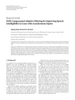
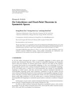
Figure 1: Angular flux ϕ(r, θ) is the rate of packets crossing a small
perpendicular line segment dx from angle (θ, θ + dθ)dividedby
dθ
· dx at the limit dθ, dx → 0.
source-destination pair. For multipath routes, it is further as-
sumed that the corresponding proportions are well defined
in P .
In this paper, we are mainly concerned with single-path
routing, but in Section 6.3 also multipath routing is consid-
ered.
Remark 2. The mean path length, that is, the mean distance
a packet travels measured in m, is given by
=
1
Λ
A
d
2
r
1
A
d
2
r
2
λ
r
1
, r
2
· s
P , r
1
, r
2
,(2)
where s(P , r
1
, r
2
) denotes the (mean) distance from r
1
to r
2
with path set P .
Example 1. For the shortest paths, we have
sp
=
1
Λ
A
d
2
r
1
A
d
2
r
2
λ
r
1
, r
2
·
r
2
− r
1
. (3)
Note that in our setting at each point the information can
flow to any direction (depending on the destination of each
packet) in contrast to the sensor networks where it can be
assumed that at any given location the information flows to
exactly one direction [2].
Probably the most important quantity for our purposes
is the packet arrival rate into the proximity of a given node.
This is described by the notion of scalar flux, which in turn
is defined in terms of the angular flux. These are similar to
corresponding concepts of particle fluxes in physics, for ex-
ample, in neutron transport theory [16]. In our case, the
packet fluxes depend on the traffic demand density λ(r
1
, r
2
)
and the chosen paths P , and are defined as follows (see also
Figure 1).
Definition 3 (angular flux). Angular flux of packets at r in
direction θ,denotedbyϕ(r, θ)
= ϕ(P , r, θ), is equal to the
rate (1/s/m/rad) at which packets flow in the angle interval
(θ, θ + dθ) across a smal l line segment of the length dx per-
pendicular to direction θ at point r divided by dx
· dθ in the
limit dx
→ 0anddθ → 0.
4 EURASIP Journal on Wireless Communications and Networking
Definition 4 (scalar flux). Scalar flux of packets (1/s/m) at r
is given by
Φ(r)
= Φ(P , r) =
2π
0
ϕ(P , r, θ)dθ. (4)
With the above notation, we can formulate the optimiza-
tion problem.
Definition 5 (load balancing problem). Find such a set of
paths, P
opt
, that minimizes the maximum scalar flux,
P
opt
= arg min
P
max
r
Φ(P , r). (5)
Remark 3 (optimal maximum traffic load). With the load
balanced paths, the maximum load is
Φ
opt
= max
r
Φ
P
opt
, r
=
min
P
max
r
Φ(P , r). (6)
In Definition 5, one needs the scalar flux Φ(P , r). In
Section 5, we will show how this can be calculated for a given
set of paths P , and in Section 6 we present a particularly sim-
ple and efficient formula for calculating the flux in a circu-
larly symmetrical system. The remaining problem of finding
the optimal paths is a difficult problem of calculus of varia-
tion. In this paper, we do not search for a general solution but
rather study three heuristically chosen families of paths and
compare their per formance with that of the shortest paths
and with the bounds introduced in the next section.
4. LOWER BOUNDS FOR SCALAR PACKET FLUX
Ournextgoalistoderivetwolowerboundsforachievable
load balancing, that is, for a given traffic demand density
λ(r
1
, r
2
), we want to find bounds for the minimum of the
maximal traffic load that can be obtained by a proper choice
of paths. These lower bounds are valid for both single and
multipath routes. Let us start with two preparatory remarks
that give additional characterizations of the scalar flux.
Remark 4. Scalar flux of packets is equal to the rate at which
packets enter a disk with diameter d at point r divided by d
in the limit when d
→ 0.
The proof follows trivially from the definitions. Note that
Remark 4 justifies the interpretation of the scalar packet flux
as a measure of spatial trafficload.
Remark 5 (density of cumulative progress rate). Scalar flux
Φ(r) can also be interpreted as the cumulative progress (m)
of packets per unit time (s) per unit area (m
2
) about point
r (rendering 1/s/m as its dimension). By progress we mean
the advance a packet has made in a given time interval in the
direction of its path.
Proof. Consider the packet flux within small angle inter val
dθ entering a small square with side h from left as shown in
Figure 2, ultimately letting dθ
→ 0andh → 0. According to
Definition 3, the rate of such packets is ϕ(r, θ)
· h · dθ.The
h
w
dθ
Figure 2: Cumulative progress in a small square.
same flow departs the square from the right side. Thus, inside
the square the cumulative progress per unit time (for packets
moving within the angle interval dθ)isϕ(r, θ)
· h · dθ · w.
Per unit area, the above yields ϕ(r, θ) dθ. Integrating over θ
then gives that Φ(r) corresponds to the cumulative progress
per unit time and unit area.
Proposition 1 (distance bound).
max
r
Φ(P , r) ≥
Λ ·
A
. (7)
Proof. The cumulative progress rate in the whole area is ob-
viously Λ
· . Thus, the right-hand side equals the average
density of progress rate, that is, the average scalar flux.
Remark 6. Accordingly, we have identity
Λ
· = A · mean Φ(r) . (8)
For example, in the absence of congestion there are no
queueing delays and the (mean) sojourn time of a packet is
proportional to the (mean) path length. Then (8) is similar
to Little’s result for the mean number of customers in a single
server queue.
Remark 7. Combining (6)and(7), we have
Φ
opt
≥
Λ
A
min
P
. (9)
It is obvious that the minimum of
is obtained when P con-
sists of the shortest paths. Denoting the corresponding mean
path length by
sp
, (cf. (3)), we get
Φ
opt
≥
Λ ·
sp
A
. (10)
Another bound is obtained by considering trafficflows
crossing an ar bitrary boundary (cf., cut bound in wired net-
works).
Proposition 2 (cut bound). For any curve C which separates
the domain A into two disjoint subdomains A
1
and A
2
,it
holds that
Φ
opt
≥
1
L
A
1
d
2
r
1
A
2
d
2
r
2
λ
r
1
, r
2
+ λ
r
2
, r
1
, (11)
where L is the length of the curve C and the double integral gives
thetotalrateofpacketsbetweenA
1
and A
2
(both directions
included).
E. Hyyti
¨
aandJ.Virtamo 5
Proof. Consider first a short line segment dx at r at some
point along the curve C.Letγ denote a direction perpen-
dicular to the curve at r such that the packets arriving from
the angles (γ
− π/2, γ + π/2) cross dx fromside2toside1,
and packets arriving from (γ + π/2, γ +3π/2) cross dx from
side1toside2.Therateλ(r)dx at which packets move across
dx is given by
λ(r)dx
=
π/2
−π/2
cos α
Φ(r, γ+α)+Φ(r, γ+α+π)
dαdx,
(12)
which yields
λ(r)dx
≤
π/2
−π/2
Φ(r, γ + α)+Φ(r, γ + α + π)dα dx
= Φ(r)dx ≤ max
x∈A
Φ(x)dx.
(13)
Integrating over the curve C completes the proof.
5. SCALAR PACKET FLUX WITH CURVILINEAR PATHS
In this section, unless stated otherwise, we assume uniform
traffic demand density. We make the assumption of unifor-
mity mainly for notational simplicity. It is easy to generalize
the results for any distribution. Also single-path routes are
implicitly assumed throughout the section.
Definition 6 (single path). Packets from r
1
to r
2
are for-
warded along a unique loop free path denoted by
p(r
1
, r
2
).
Next, we give some additional properties that character-
ize the single-path routes considered in this study.
Definition 7 (bidirectionality). The paths are bidirectional if
p(r
2
, r
1
)is
p(r
1
, r
2
) in reverse direction.
Note that a flow on a given path contributes to the scalar
flux at any point on the path by an amount equal to the ab-
solute size of the flow, no matter what the direction of the
flow is. Thus, allowing a different return path is, from the
load balancing point of view, essentially equivalent to allow-
ing two paths for each pair of locations.
Definition 8 (destination-based forwarding). The paths ad-
here to a destination-based forwarding rule if
r
∈
p
r
1
, r
2
=⇒
p
r, r
2
⊂
p
r
1
, r
2
. (14)
The above definition means that the routing decision
made at each point depends on the destination of the packet
only, not on the source. Fixing destination x induces a set
of curves along which the packets are routed towards x (see
Figure 9 for illustration). Together with bidirectional paths
(Definition 7), the same curves also describe how the packets
from x are forwarded to all possible destinations.
Definition 9 (path continuity). Path continuity is satisfied if
r
∈
p
r
1
, r
2
=⇒
p
r
1
, r
2
=
p
r
1
, r
∪
p
r, r
2
. (15)
Note that (i) Definitions 7 and 8
⇒ Definition 9, and (ii)
Definition 9
⇒
Definition 8. In this section we, however, as-
sume that the set of paths is defined by a family of continuous
curves.
Definition 10 (paths defined by curves). Paths are defined by
afamilyofcurvesC for which it holds that
(i) the curves are continuous, piecewise smooth, and
loop-free;
(ii) given two points r
1
and r
2
, there exists a unique
curve c
∈ C to which both points belong. This curve
then defines the path
p(r
1
, r
2
).
From Definition 10, it follows that also Definitions 6–9
are satisfied. Moreover, unambiguity of curves in condition
(ii) implies that the curves may not cross each other except at
x (and possibly at the endpoints, which can be neglected). In
particular, Definition 10 allows one to characterize the curves
going through x according to their direction at x. To this end,
consider a small
-circle at x and an arbitrary point x outside
the circle. According to condition (ii), there is a unique con-
tinuous curve c connecting r to x, which defines the path
from r to x. This path cuts the circumference of
-circle at
a certain point r
. Furthermore, unambiguity of the curves
ensures that c is the only curve to which x and r
belong,
thus defining the direction θ in the limit
→ 0. Hence, we
let p(x, θ) denote a curve going through point x in direction
θ. T he points along the curve are denoted by
p(x, θ, s), s
∈
− a
1
, a
2
, a
1
, a
2
> 0, (16)
where p( x, θ,0)
= x,anda
1
and a
2
denote the distances to
the boundary along the curve in opposite directions.
For simplicity of notation, we furthermore assume that
the curves defining the paths towards (and from) x start
from the boundary. Then, a
1
= a
1
(x, θ)anda
2
= a
2
(x, θ).
In general, we can also allow closed curves and curves with
endpoints inside the domain. For the closed curves, one
must explicitly define which direction is to be taken. Thus,
in this case, a
1
= a
1
(x, θ) defines the maximum distance
from x along path p(x, θ) in “negative direction” from where
a packet is forwarded across point x to the “positive side.”
Similarly, a
2
= a
2
(x, θ, s) defines the maximum distance
on the “positive side,” measured from x, to where nodes
about p(x, θ,
−s), 0 <s<a
1
, communicate to using the
path p(x, θ). This complicates the notation unnecessarily,
and thus in the following we assume that the cur ves start
and end at the boundary. However, it is straightforward to
show that essentially the same results hold also in the gen-
eral case where some of the curves may be closed or have the
endpoints inside the domain.
Definition 11 (curve divergence). Let h(x, θ, s) denote the
rate with respect to the angle θ at which curves going through
x diverge at the distance of s,
h(x, θ, s)
=
∂
∂θ
p(x, θ, s)
. (17)
6 EURASIP Journal on Wireless Communications and Networking
x
x
dθ
θ
ds
A
s
θ
(a)
x
x
dθ
θ
h
x
A
d
θ
(b)
Figure 3: Derivation of expression (18) for the scalar flux.
The curve divergence is assumed to be (piecewise) well
defined and finite with a given set of curves.
Proposition 3 (angular flux with curvilinear paths). For uni-
form traffic demand density, λ(r
1
, r
2
) = Λ/A
2
,theangularflux
at point x in direction θ is given by
ϕ(x, θ)
=
Λ
A
2
a
1
0
h(x, θ, −s
)
h(x
, θ
, s
)
a
2
0
h(x
, θ
, s+s
)dsds
,
(18)
where x
= p(x, θ, −s
) and θ
is the direction of the path at x
(see Figure 3).
Proof. Without loss of generality, we may assume that Λ
= 1.
The aim is to determine the angular flux at x in direction θ.
To this end, consider path p(x, θ, s), where s denotes the posi-
tion on path relative to x (positive in one direction, negative
in other). Assume that a particular source contributing the
angular flux is located in a differential area element about
point x
(see Figure 3(a)),
x
= p(x, θ, s
), s
≤ 0, (19)
for which it clearly holds that (the same curve)
p(x
, θ
, s − s
) = p(x, θ, s). (20)
Let dθ denote a differential angle at x as illustrated in
Figure 3(a). A ccording to (17), the differential source area
about x
is given by
A
s
= h(x, θ, s
) · dθ · ds
. (21)
Similarly, let dθ
denote a small angle at point x
,which
yields a destination area of
A
d
=
a
2
0
h(x
, θ
, s − s
)dsdθ
, (22)
as illustrated in Figure 3(b). The curve divergence at x
tells
us the perpendicular distance of two paths passing x
in di-
rections θ
and θ
+ dθ
as a function of the distance s
along
the path. Thus, the height of the “target line segment” per-
pendicular to the path at point x is h
x
= h(x
, θ
, −s
) · dθ
,
and the contribution to the angular flux from the differential
source area A
s
about x
is
dϕ
=
A
s
· A
d
A
2
· dθ · h
x
=
1
A
2
·
1
dθ
·
1
h(x
, θ
, −s
) · dθ
·
h(x, θ, s
) · dθ · ds
·
a
2
0
h(x
, θ
, s − s
)dsdθ
=
1
A
2
·
h(x, θ, s
)
h(x
, θ
, −s
)
·
a
2
0
h(x
, θ
, s − s
)dsds
.
(23)
Consequently, the angular flux at x in direction θ is given by
ϕ(x, θ)
=
1
A
2
0
−a
1
h(x, θ, s
)
h(x
1
, θ
, −s
)
a
2
0
h(x
, θ
, s−s
)dsds
.
(24)
The proposition follows upon substitution s
←−s
.
Remark 8 (angular flux with nonuniform λ(r
1
, r
2
)). It is
straightforward to generalize (18) to the case of nonuniform
traffic demand density λ(r
1
, r
2
). In this case, the angular flux
at x in direction θ is given by
ϕ(x, θ)
=
a
1
0
h(x, θ, −s
)
h(x
, θ
, s
)
·
a
2
0
λ
x
, p(x
, θ
, s+s
)
·
h(x
, θ
, s+s
)dsds
.
(25)
Example 2 (shortest paths). For the shortest paths, that is,
straight lines,
h(x, θ, s)
=|s|, (26)
and the angular flux is given by
ϕ(x, θ)
=
a
1
0
a
2
0
λ
r
1
, r
2
·
(s + s
)dsds
, (27)
where r
1
= x − s
e
θ
,andr
2
= x + s e
θ
,withe
θ
denoting the
unit vector in direction θ. Consequently, for uniform traffic
demand density,
ϕ(x, θ)
=
Λ
A
2
a
1
0
a
2
0
(s+s
)dsds
=
Λ
2A
2
a
1
a
2
a
1
+a
2
,
(28)
in accordance with the result on RWP model in [17].
Remark 9 (optical paths). A family of paths can be defined in
terms of paths of light rays in an optical medium with index
of refraction n(x). For optical paths, it can be shown with the
aid of Snell’s law that
h(x, θ,
−s
)
h(x
, θ
, s
)
=
n(x)
n(x
)
. (29)
E. Hyyti
¨
aandJ.Virtamo 7
Substituting (29) into (18) yields
ϕ(x, θ)
=
n(x)
A
2
a
1
0
a
2
0
h(x
, θ
, s + s
)
n(x
)
dsds
. (30)
It is worth noting that the optical paths minimize the mean
travelling time assuming that the velocity of the packet is
inversely proportional to the index of refraction,
min
p:p(0)=r
1
, p()=r
2
0
n
p(s)
ds. (31)
6. UNIT DISK WITH UNIFORM TRAFFIC DEMANDS
In this section, we will demonst rate how the proposed
framework can be applied. To this end, we consider a special
case of a unit disk with uniform load,
A
=
r ∈ R
2
: |r| < 1
, λ
r
1
, r
2
=
Λ
π
2
. (32)
First, we study the performance of two simple families of
paths: outer and inner radial ring paths. The performance
of these path sets is compared with that of the shortest paths,
and with the appropriate lower bounds for the minimal max-
imum traffic load. Then we focus on a general family of paths
and derive computationally efficient expression for calculat-
ing the packet flux distribution in this sp ecial case of unit.
Using these expressions we further evaluate the so-called cir-
cular and modified circular path sets, where the parameters
of the latter form are optimized.
Example 3 (shortest paths in unit disk). For transport ac-
cording to the straight line segments, we can either use (28)
or rely on the results for the RWP model (see [15]). Accord-
ingly, the scalar flux at the distance of r from the origin is
given by
Φ
sp
(r) =
2(1 − r
2
) · Λ
π
2
π
0
1 − r
2
cos
2
φdφ. (33)
The function Φ
sp
(r) is depicted in Figure 5 (denoted by SP).
In particular, the maximum flux is obtained at the centre,
Φ
sp
(0) =
2
π
· Λ ≈ 0.637 · Λ. (34)
Example 4 (distance bound for unit disk). The distance
bound gives a relationship between the obtainable maximum
load and the mean path length. With shortest paths, we have
sp
= 128/45π which upon substitution in (10) yields
Φ
opt
≥
Λ · 128
45π
2
≈ 0.288 · Λ. (35)
Example 5 (greatest sensible mean path length). With the aid
of (34), we can write the distance bound (7)intermsofΦ
sp
,
max
r
Φ(P , r) ≥ Φ
sp
·
2
. (36)
Shortest paths are not optimal for uniform trafficdemand
density. But the above relation says that in searching for a
better set of paths (which necessarily has
≥
sp
), one can
outright reject such path sets for which
>2 since for them,
the maximal scalar flux surely is greater than that for the
shortest paths. That is, in order to lower the maximal flux,
one has to bend the paths away from the loaded region but
without increasing the mean length of the paths too much at
the same time.
Example 6 (cut bounds for unit disk). Let us consider two
curves, a diameter C
1
separating the unit disk into two
semicircles, and a concentric circle C
2
with radius r,0<r<1.
For the packet rate λ
1
across C
1
, it holds that λ
1
≥ Λ/2, and
Φ
opt
≥
Λ
4
= 0.25 · Λ. (37)
Similarly, the packet rate across C
2
is bounded by λ
2
(r) ≥
2r
2
(1−r
2
) · Λ, which corresponds to radial flux
Φ
r
(r) =
2r
2
1 − r
2
2πr
· Λ =
r − r
3
π
· Λ. (38)
By the cut bound we have Φ
opt
≥ Φ
r
(r). The tightest lower
bound is obtained by maximizing Φ
r
(r)withrespecttor,
Φ
opt
≥ Φ
r
1
√
3
=
2
3
√
3 · π
· Λ ≈ 0.123 · Λ. (39)
We see that in the case of unit disk with uniform traf-
fic demand density, the distance bound provides the tightest
lower bound for the solution of the minmax problem (6).
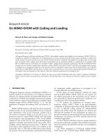
6.1. Radial ring paths
Let us consider next the three actual path sets illustrated in
Figure 4. The shortest paths (SPs) are equivalent to RWP
model as has been already mentioned. The two radial path
sets, referred to as “Rin” and “Rout,” are similar in the sense
that each path consists of two sections. One section is a radial
path towards (or away from) the origin, and the other section
is an angular path along a ring with a given radius. The dif-
ference between the two sets is the order of sections, “Rin”
uses the inner angular rings and “Rout” the outer ones, as
the names suggest. Note that locally, at any point, the pack-
ets are transmitted only in 4 possible directions (2 radial and
2 angular), which may simplify the possible implementation
of the time-division multiplexing. It is easy to see that the
radial ring paths satisfy Definitions 6–9, but not condition
(ii) of Definition 10. Thus, (18) cannot be used to calculate
the scalar packet flux. However, given their simple form, the
scalar packet flux can be easily obtained by other means.
In particular, when considering the arrival rate into a
small area at the distance of r from the origin, one needs
to consider only two components: (1) the radial component
and (2) the angular component. The radial component of the
flux is the same for both path sets, that is,
Φ
r
(r) =
r − r
3
π
· Λ. (40)
8 EURASIP Journal on Wireless Communications and Networking
Rout
Source
SP
Destination
Rin
(a) Three path sets
θ
r
Source, A
s
dθ
Destinations, A
d
Target
(b) Rin
θ
r
Source, A
s
dθ
Destinations, A
d
Target
(c) Rout
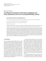
Figure 4: Radial ring paths. (a) illustrates the three path sets considered: straight line segments (SP), radial paths w ith outer (Rout) and
inner (Rin) angular ring transitions. (b) illustrates the derivation of the angular ring flux at the distance r from the origin for Rin paths, and
(c) for Rout paths.
6.1.1. Inner radial ring paths
Let us next consider inner radial ring paths. We want to de-
termine the flux along the ring at the distance of r. To this
end, consider a small line segment from (
−r,0)to(−r −Δ,0)
as the target line segment, as illustrated in Figure 4(b).Pack-
ets originating from a smal l source area A
s
at the distance
of r in direction θ travel through the target line segment if
their destination is in the destination area A
d
. The size of the
source area is
A
s
= r · Δ · dθ, (41)
while the possible destination area is
A
d
=
1 − r
2
2
· θ. (42)
Combining the above with λ
= Λ/π
2
, and taking into ac-
count the symmetries (factor of 4), gives the angular compo-
nent of the flux at the distance of r,
Φ
θ
(r) =
4Λ
Δπ
2
π
0
1 − r
2
2
θrΔdθ
=
r − r
3
Λ.
(43)
Hence, the total flux at the distance r for the outer path set is
given by
Φ
Rin
(r) = Φ
r
(r)+Φ
θ
(r) =
(π +1)
r − r
3
π
· Λ. (44)
The maximum is obtained at r
= 1/
√
3,
Φ
Rin
1
√
3
≈
0.507 · Λ. (45)
6.1.2. Outer radial ring paths
For outer radial ring paths, we find by similar consideta-
tions (see Figure 4) that destination area of the packet going
through the target line segment is r
2
/2 ·θ.Thuswehave
Φ
θ
(r) =
4Λ
Δ π
2
π
0
r
2
2
· θ · r · Δdθ = r
3
· Λ. (46)
Combining the above with ( 40)gives
Φ
Rout
(r) =
(π − 1)r
3
+ r
π
· Λ. (47)
The maximum flux is obtained at r
= 1,
Φ
Rout
(1) = Λ. (48)
6.1.3. Comparison of radial ring and shortest paths
The resulting scalar packet fluxes for these three path sets are
illustrated in Figure 5 as a function of the distance r from
the centre. It can be seen that each of them exhibits a rather
distinctive form, none of which is flat. The key performance
quantities are given in Ta ble 1. Thus, the outer version leads
to a clearly higher maximum load than the shortest paths
while the inner version yields a slightly better solution.
According to (8), there is a direct relationship between
the mean path length and the average scalar packet flux, that
is, in unit disk with Λ
= 1,
mean Φ(r)
= π · . (49)
Consequently, by definition, the shortest-path routes yield
always the minimum average scalar flux, and in order to de-
crease the maximum scalar flux one must at the same time
increase the average scalar flux.
As mentioned, the shortest paths tend to concentrate too
much traffic in the center of the area. The main shortcom-
ing with the outer radial ring paths is easy to illustrate by
E. Hyyti
¨
aandJ.Virtamo 9
SP
Rin
Rout
1
0.8
0.6
0.4
0.2
Φ(r)
10.80.60.40.2
r
Shortest paths (SP)
Rin
Rout
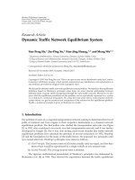
Figure 5: In the graph on left the resulting flux is plotted as a function of distance r from the center for the three path sets (SP, Rin, and
Rout) in unit disk (Λ
= 1). The 3D graphs on the right illustrate the same situation.
Table 1: Results w ith shortest and radial ring paths (Λ
= 1).
Path set Max. flux, max Φ(r) Average flux, mean Φ(r) Mean path length
Shortest paths (SP)
2
π
≈ 0.637
128
45π
2
≈ 0.288
128
45π
≈ 0.905
Inner radial ring (Rin)
2+2π
3
√
3π
≈ 0.507
4+4π
15π
≈ 0.352
4+4π
15
≈ 1.104
Outer radial ring (Rout)
1
4+6π
15π
≈ 0.485
4+6π
15
≈ 1.523
an example. Consider a situation where a source node is lo-
cated near the origin, for example, about (
, 0), and the des-
tination is near the circumference about (1
− ,0). In such
cases, the packet is first forwarded to a totally opposite di-
rection until it reaches the perimeter and then along a half-
circle to the destination, that is, the chosen route is clearly
unefficient and contributes unnecessarily to the trafficload
near the perimeter. Also the inner radial ring paths evade the
center area too much. In the next section, we consider better
smooth cur vilinear paths which yield better performance in
terms of a lower maximum scalar flux.
6.2. General paths in unit disk
While (18) provides a general formula for calculating the
angular flux in the general case, and the scalar flux is then
obtained by integration over angles (4), in the special case of
circularly symmetric system the calculation of the scalar flux
can b e done in a simpler way by making full use of the sym-
metry. In this way we derive an explicit formula for the scalar
flux as a function of the radius for a general family of paths.
We then demonstrate the use of this formula for the mini-
mization of the maximum flux with a two-parameter family
of paths.
To begin with, we need a few definitions. The basic set of
paths is given by the set of curves y
= y(x, a), where y(x, a)is
an even function of x, y(x, a)
= y(−x, a), that is, the curves
are in a “horizontal position,” meaning for instance that the
derivative is zero at x
= 0. For each curve y(x, a), also its
mirror image with respect to the x-axis,
−y(x, a), belongs to
the basic set. Without loss of generality, we can choose the
y(x, a) = a
a
y(x, a)
a
Figure 6: Basic set of paths defines a unique path for each value
of parameter a. Paths on the left figure correspond to the short-
est paths (i.e., straight line segments) and paths on the right corre-
spond to the circular paths (see Example 7).
curve parameter a so that y(0, a) = a, a ∈ [−1, 1]. We make
also the reasonable assumption of the type of paths that for
a
≥ 0, it holds that 0 ≤ y(x, a) ≤ y(0, a)forallx. Then a
is the “height” of the curve. From these definitions, it follows
that y(x,
−a) =−y(x, a) and also that y(x,0)= 0, that is, the
path corresponding to value a
= 0 is the horizontal diagonal
of the disk.
We assume that the curves in the basic set fill the unit
disk completely so that each interior point of the disk be-
longs to one and only one path in the basic set, see Figure 6
for illustration. From the basic set of paths, the full set of
paths is obtained by rotations of the whole set around ori-
gin by an angle in the range [0, π]. In the full set of paths,
there is a unique path through any given point in any given
10 EURASIP Journal on Wireless Communications and Networking
y(x, a)
a
(X, Y)
θ(r, a)
A(a)
φ(r, a)
r 1
Figure 7: Notation for basic paths.
direction (see Figure 9, for an example for a full set of paths
going through a given point).
Some additional notation needs to be introduced. Partial
derivatives are denoted as
y
x
(x, a) = ∂
x
y(x, a) =
∂
∂x
y(x, a),
y
a
(x, a) = ∂
a
y(x, a) =
∂
∂a
y(x, a).
(50)
X(r, a), a
≤ r, is defined as the positive x-coordinate of the
intersection point of the a-path y(x, a) and the circle with ra-
dius r, that is, the positive solution x of the following equa-
tion
1
:
x
2
+ y(x, a)
2
= r
2
. (51)
The corresponding y-coordinate of the intersection point is
denoted as Y(r, a)
= y(X(r, a), a). The angle between the
vector to this point and the x-axis is denoted by φ(r, a),
φ(r, a)
= arctan
Y(r, a)
X(r, a)
. (52)
Finally, the angle of incidence of curve y(x, a)andr-circle is
denoted by θ(r, a), that is, this is the angle between the tan-
gent of the curve and the normal of the circle at the point of
intersection. See Figure 7 for the illustration of these defini-
tions.
In order to calculate the scalar flux Φ(r), we start by con-
sidering the contribution from a source point at distance
s
≥ r from the origin (see Figure 8). Instead of focusing on a
given destination point and trying to determine the angular
flux at that particular point, we can consider the contribu-
tion of the source point to the flux at any point on the cir-
cle with radius r. So in the first step, we calculate the total
flow I(r, a; s) from the source point across the circle along
the paths with parameter less than or equal to a. By symme-
try, this flow is the same for all source points at distance s
and the total contribution from all source points within an
annulus with radius in the range (s, s + Δs)is2πsΔsI(r, a; s).
Having summed the flows from all the sources within an an-
nulus, the resulting flow across the r-circle is symmetric and
1
It is assumed that there are only two solutions ±X(r, a) to this equation.
This is not true, for instance, for strongly bell-shaped paths, for which the
analysis is more complicated.
a
θ(r, a)
A
1
A
2
A
3
(s)
A
4
θ(r, a)
φ(r, a)
Source
r
r-circle
φ(s, a)
s
Figure 8: Calculating the total traffic flow from a source point at
distance s from the or i gin crossing the r-circle.
the intensity of the flow at any point of the circle is obtained
by dividing by the length of the circumference, 2πr, resulting
in intensity I(r, a; s) sΔs/r.
In the above discussion, we considered a partial intensity
by restricting ourselves to paths with parameter less than or
equal to a. This makes it possible to fi nd the angular flux at
distance r. By partial derivation with respect to a,wehave
that the intensity of flow, from sources in the annulus, across
the circle along paths in the parameter range (a, a + Δa)is
∂
a
I(r, a; s) sΔs Δa/r. All these paths meet the r-circle at the
incidence angle θ(r, a). By dividing the above expression by
cos θ(r, a), we get the angular flux (times the angle difference
Δθ corresponding to the parameter difference Δa). This is so
because, conversely, given angular flux ϕ(θ), the flow across
the surface is given by
ϕ(θ)cosθdθ. Now, the scalar flux is
obtained by integrating over all angles. In addition, we inte-
grate over all source distances r
≤ s ≤ 1, yielding
Φ(r)
=
1
r
r
0
da
1
r
dss
∂
a
I(r, a; s)
cos θ(r, a)
. (53)
Next we focus on determining I(r, a; s) and at the same
time explain why the source point can be restricted to be
outside the r-circle. As the total flow of the packets per sec-
ond in the whole area is Λ, the source-destination density of
flow (per unit area at the source and per unit area at the desti-
nation) is Λ/π
2
. Then the total flow from the source (per unit
area at the source) across the circle along paths with param-
eter at most a is obtained by considering the “target area,”
I(r, a; s)
=
4Λ
π
2
A
1
+ A
2
+ A
3
, (54)
where A
1
, A
2
,andA
3
are the three shaded areas depicted in
Figure 8. The factor 4 comes because, first, we have the same
areas below the diagonal and, second, for areas A
2
and A
3
we have to take into account that the flow from the source
crosses the circle twice, once in, once out (both times at the
same angle of incidence). For area A
1
,wehavetotakeintoac-
count that when restricting explicitly the source point to be
E. Hyyti
¨
aandJ.Virtamo 11
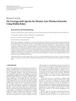
Figure 9: Circular paths are paths formed by the circumferences of circles which cross the unit disk at the opposite points.
outside the circle, we have neglected the equal flow from in-
side sources to outside, and this has to be compensated for by
another factor of 2. For areas A
2
and A
3
, this further doubling
is not needed, since the source point is let to be located at any
point outside the circle, also in these areas.
The areas A
1
and A
2
are independent of s allowing us to
make the s-integration in (53),
1
r
sds = (1/2)(1 − r
2
). By
inspection of Figure 8, the area A
3
is found to be (1/2)(1 −
r
2
)φ(s, a). The s-dependent factor φ(s, a) can also now be
integrated:
1
r
sφ(s, a)ds = A
4
,whereA
4
is the rightmost
shaded area in Figure 8. From the figure, we further see that
total area of A
1
, A
2
,andA
4
equals the area between the a-
curve and the corresponding diagonal, denoted by A(a)in
Figure 7. Collecting the above pieces together, we finally end
up with the simple result
Φ(r)
=
2 Λ
π
2
1−r
2
r
r
0
A
(a)
cos θ(r, a)
da, (55)
where
A
(a) =
X(1,a)
−X(1,a)
y
a
(x, a) dx,
cos θ(r, a)
=
X(r, a)+Y (r, a)y
x
X(r, a), a
r
1+y
x
X(r, a), a
2
.
(56)
The former is obvious, and the latter follows, upon ap-
plying a trigonometric identity, from the observation that
θ(r, a) is the difference between the angle φ(r, a)
=
arctan Y(r, a)/X(r, a) and the (negative) angle of slope,
arctan y
x
(X(r, a), a), of the tangent of the a-path at x =
X(r, a), see Figure 7.
Because of the factor cos θ(r, a) in the denominator, the
integrand of (55 ) has a singularity at the upper limit of in-
tegration a
= r, where cos θ(r, r) = 0. This is, however, an
unessential singularity meaning that the integral is conver-
gent. It may still cause some problems in numerical integra-
tion. The problems can be avoided by a simple change of
variable of integration from a to α defined by a
= r cos α,
α
∈ [0, π/2].
As a check, consider the flux resulting from the use of
shortest paths, that is, straight lines. Then we have θ(r, a)
=
φ(r, a)andr cos θ(r, a) =
√
r
2
− a
2
. It also holds that A
(a) =
2
√
1 − a
2
. Using (55) and the above change of variable, a =
r cos α,(55) is rederived.
By a limit consideration,
2
an even simpler expression can
be derived from (55) for the flux at the centre,
Φ(0)
=
Λ
π
A
(0) =
Λ
π
1
−1
lim
a→0
y(x, a)
a
dx. (57)
The integrand in the latter form is a “very low a”-curve nor-
malized so that the normalized curve has the height 1.
Example 7 (circular paths). As a first example, we consider
a set of curvilinear paths, referred to as circular paths,which
consist of such sections of circumference of circles (with ra-
dius
≥ 1) that cut the unit disk at the opposite points as illus-
trated in Figure 9 (see also Figure 6). From the figure, it can
be seen that these paths smoothly move some portion of the
traffic away from the centre of the disk. In passing, we note
that the circular paths belong to the family of optical paths,
and are obtained with the index of refraction profile
n(r)
=
n(0)
1+r
2
. (58)
Additionally, there is an analogy between the circular paths
and electrostatics. The circular paths can be interpreted as
electrical field lines of the 2D field between two line charges
(perpendicular to the plane of the figure).
The equation for the basic set of circular paths is
y
circ
(x, a) =
(1 − x
2
)+
1 − a
2
2a
2
−
1 − a
2
2a
. (59)
For a
= 1, the function is
√
1 − x
2
,whereasforsmalla it is
approximately a(1
− x
2
).
The scalar flux calculated using (55) is depicted in
Figure 10 (the middle curve). It can be seen that the traffic
load is fairly well distributed. The maximum flux is obtained
at the centre of the disk, where the exact result given by (57)
is
Φ
circ
(0) =
4
3π
· Λ ≈ 0.424 · Λ. (60)
2
When r → 0anda ∈ [0, r], we have A
(a) → A
(0). Further, all
basic paths inside the r-circle tend to straight horizontal lines and
r cos θ(r, a)
→
√
r
2
− a
2
. The integral can then be done,
r
0
da/
√
r
2
− a
2
=
π/2.
12 EURASIP Journal on Wireless Communications and Networking
SP
circ
mod
0.6
0.5
0.4
0.3
0.2
0.1
Φ(r)
10.80.60.40.2
r
Shortest paths (SP)
Circular
Modified circular
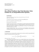
Figure 10: Scalar flux as the function of the r adius for shortest paths, circular paths, and two-parameter modified circular paths with
optimized parameters (Λ
= 1).
This is precisely 2/3 of the scalar flux with the shortest paths
(cf., Example 3) and is also smaller than the maximal scalar
fluxes with the ring paths. The factor 2/3 simply follows from
the fact that the area under the parabola y
= 1 − x
2
, x ∈
[−1, 1], is 2/3 of the area below the line y = 1 (and above the
x-axis), that is, the setting of Figure 6 in the limit a
→ 0.
Example 8 (modified circular paths). From (57), one sees
that the flux at the centre can be made arbitrarily small by
changing the shape of small-a paths to a bell shape. The area
under such a bell curve (normalized to have the height 1) is
the smaller the sharper the bell is. Of course, the flux at the
centre can be made very smal l only at the expense of making
it larger somewhere else; this is exactly the tradeoff we are
trying to balance. To this end, we modify the basic curves as
follows:
a
1
a
y
circ
(x, a)
β+(1−β)a
, (61)
which for small a indeed makes the curve more bell-shaped,
a(1
−x
2
)
β
(when β>1), while leaving the outer curves a ≈ 1
untouched (the exponent is close to 1). In order to control
in more detail how the exponent changes from β to 1 when
a varies from 0 to 1, we change the expression further by in-
troducing another tunable parameter γ as follows:
y
mod
(x, a | β, γ) = a
1
a
y
circ
(x, a)
β+(1−β)a
γ+(1−γ) a
. (62)
In principle, the exponent of a in the exponent could sim-
ply be γ but we found the present slightly more complicated
form to work better.
With this two-parameter (β, γ)-family of paths, we can
again numerically calculate the scalar flux Φ(r) using (55).
The parameters can even be optimized in order to minimize
the maximum flux. The lowest maximum flux
min
β,γ
max
r
Φ
mod
(r) ≈ 0.384 · Λ (63)
was obtained approximately at β
= 1.45 and γ = 12.2.
The basic path set for these optimal parameters is shown in
Figure 11. Visually, the paths are very similar to the circular
Figure 11: Modified circular paths with the optimized parameters
β
= 1.45 and γ = 12.2.
ones but one can distinguish the slightly bell-shaped form of
the lowermost curves.
The corresponding flux as a function of radius is shown
in Figure 10 (the lowest curve) and is compared with simi-
lar curves for shortest paths and (unmodified) circular paths.
The flux distribution with the modified circular paths is re-
markably flat and probably cannot be much improved with
any other family of paths. It can be conjectured that with op-
timal paths, the flux is constant up to a certain distance and
then falls to zero. This kind of conjecture is supported by the
well-known behavior of optimimal load balancing in finite
networks obtained by solving an LP problem: typically the
links in the center of the network are constraining, realizing
the same maximum utilization, while links at the outer parts
are not, and in fact the solution is not unique.
6.3. Randomized path selection approach
One option to achieve a lower maximum load is to allow
the use of several paths for each pair of nodes (similarly as
in [6, 7]). To this end, let us relax our assumptions and al-
low a finite number of path sets
{P
i
},wherei = 1, , n.
Upon transmission of a packet, the source node chooses a
path from path set P
i
with probability of p
i
, i = l, , n.
Remark 10 (packet flux with randomized path sets). Ran-
domized path selection upon transmission from path sets
{P
i
} with probabilities p
i
, i = 1, , n, yields a scalar packet
flux of
Φ(r)
=
i
p
i
· Φ
P
i
, r
. (64)
E. Hyyti
¨
aandJ.Virtamo 13
rnd1
rnd2
0.5
0.4
0.3
0.2
0.1
Φ(r)
10.80.60.40.2
r
rnd1
0.61
· Φ
sp
+0.39 ·Φ
Rout
rnd2
0.5027
· Φ
sp
+0.3763 ·Φ
Rout
+0.121 ·Φ
Rin
Figure 12: Scalar flux as a function of the radius r for the two e lementary randomized path sets rnd1 and rnd2, which are obtained by
relaxing the assumption of single-path routing (Λ
= 1).
Example 9. Consider uniform traffic demand density in unit
disk and two elementary path sets: (1) shortest paths, and (2)
the outer radial paths. Weights p
1
= 0.61 and p
2
= 0.39 give
ascalarpacketfluxof
Φ(r)
= 0.61 · Φ
sp
(r)+0.39 · Φ
Rout
(r). (65)
The resulting flux is rather constant as illustrated in Figure 12
with label “rnd1.” The maximum is 0.397
· Λ. The same tech-
nique can be taken further, for example, by combining all
three elementary path sets as follows:
Φ(r)
=0.5027·Φ
sp
(r)+0.3763 ·Φ
Rout
(r)+0.121·Φ
Rin
(r),
(66)
which gives a maximum flux of 0.3763
· Λ corresponding to
Φ
Rout
(r) at the circumference (see curve with label “rnd2” in
Figure 12). Similarly, the results with circular and modified
circular paths can be slightly improved by moving a fraction
of traffic to Rout paths.
Remark 10 may have one interesting application. First we
note that as a single path between any source-destination pair
is a special case of the randomized path selection, the optimal
solution to the latter problem can never be worse. For the
uniform traffic pattern in unit disk, we made a conjecture
that the scalar flux obtained with an optimal (basic) set of
paths is a constant up to some distance r
∗
and then decreases
to zero which is achieved at r
= 1, that is, the scalar flux
would be a concave function of r. With Rout paths, the scalar
flux is zero at r
= 0 and then a strictly increasing convex
function reaching a value 1 at r
= 1. Thus, if the distance
at which the fluxes of these two path sets are equal is strictly
larger than r
∗
, then the maximum scalar flux can be further
lowered by moving a small portion of traffic to Rout paths.
In particular, this would mean that by using multiple paths a
higher relative increase in traffic demands could be sustained
than with a single-path routing.
6.4. Discussion
In general, deciding on the routes involves considering sev-
eral factors and is not a straightforward task. In fact, often
it may be sufficient to simply use the shortest paths. In this
paper, we have focused on the problem of load balancing,
where, instead of using shortest paths, part of the trafficis
deliberately routed along slightly longer paths in order to re-
duce the load in the most highly congested links. In our con-
text of dense multihop networks, this tr a nslates to minimiz-
ing the maximum scalar flux, that is, finding such a set of
paths which allows a maximal increase in traffic(withagiven
traffic pattern) the network can sustain.
This, however, has several unfavorable effects at times
when the traffic load is low. Firstly, as the mean number
of hops increases, the round-trip times become higher. Sec-
ondly, the higher mean number of hops also leads to a higher
energy consumption, which can be an important factor, for
example, for battery-powered wireless multihop networks.
In other words, there is a tradeoff between the mean path
length (corresponding to delay and energy consumption in
lightly loaded network) and the maximum sustainable traf-
fic intensity with a given traffic pattern. In particular, the
shortest paths represent the optimal set of paths under lightly
loaded network and the optimal load balanced paths allow
the maximal increase with given trafficpattern.
These two criteria can be combined by giving arbit rary
weights for both objectives. The optimal set of paths for
eachcombinedobjectivehassomemeanpathlengthand
maximum scalar flux, which can be represented as a point
in (
,maxΦ(r))-space. These points are Pareto optimal and
form a concave curve with endpoints corresponding to the
shortest paths and to the optimal load balanced paths.
In order to illustrate this, in Figure 13 we have plotted the
points corresponding to the different path sets for unit disk
considered earlier together with two lower bounds. The x-
axis corresponds to the mean path length
, which, according
to (8), can be obtained from the scalar flux,
=
1
Λ
A
Φ(r)d
2
r =
A
Λ
· mean Φ(r), (67)
and the y-axis to the maximum scalar flux,
max
r∈A
Φ(r). (68)
14 EURASIP Journal on Wireless Communications and Networking
SP bound
SP
circ
mod
Rin
Rout
rnd1
rnd2
Distance bound
1
0.8
0.6
0.4
max
r
Φ(r)
1.51.41.31.21.110.9
Mean path length
Figure 13: Comparison between the mean path length (i.e., overall
forwarding load in the network) and the maximum scalar flux (i.e.,
traffic load) for different path sets in unit disk uniform trafficde-
mands (Λ
= 1).
By definition, no path set yields a lower mean path length
than the shortest paths which gives a lower bound for the
mean path length denoted by “SP bound.” The distance
bound is given by (7).
From the figure, it can be seen that the radial ring paths
(Rin and Rout) clearly are not even close to Pareto optimal
while the other three path sets (SP, circular, and modified
circular) can be justified with different objectives or con-
straints. Furthermore, the randomized path sets (rnd1 and
rnd2) obtained by combining the shortest paths and radial
ring path(s) achieve a low maximum scalar packet flux, but
at the same time increase unnecessarily the mean path length.
This is due to the use of Rout paths to move a portion of traf-
fic away from the center. The fact that they are close to the
distance bound is due to a rather constant scalar packet flux
as illustrated in Figure 12.
7. CONCLUSIONS
In this paper, we have presented a general framework for an-
alyzing traffic load and routing in a large dense multihop
network. The approach relies on strong separation of spa-
tial scales between the microscopic level, corresponding to
the node and its immediate neighbors, and the macroscopic
level, corresponding to the path from the source to the des-
tination. In a dense wireless network with this property the
local traffic load can be assimilated with the so-called scalar
(packet) flux. The scalar flux is bounded by a maximal value
that the network with a given MAC and packet forwarding
protocol can sustain. The scalar flux depends on trafficde-
mand density λ(r
1
, r
2
) and the chosen set of routing paths
P . The load balancing problem thus comprises determining
the set of routing paths such that the maximal value of the
flux in the network is minimized. While the genera l solution
of this difficult problem remains for future work, our main
contribution in this paper consists of giving bounds for the
scalar flux and giving a general expression for determining
the scalar flux at a given point for a given set of curvilinear
paths.
A particular attention was given to the special case of unit
disk with uniform traffic demands for which we have derived
a simple computationally efficient expression for calculating
the scalar flux for any family of paths. In this case, we were
able to reduce the general three-dimensional integral equa-
tion to a two-dimensional one, which is both numerically
stable and convenient to evaluate.
Theseresultsareillustratedbynumericalexampleswith
different heuristically chosen sets of paths, and also by opti-
mizing a parameterized set of paths. In particular, as a result
of optimization, we have found a set of paths with a remark-
ably flat scalar flux distribution and the maximum scalar flux
reduced by about 40% when compared to the shortest paths.
In this paper, we have limited our attention to specific types
of paths satisfying the so-called path continuity condition.
This may be an unnecessarily restrict ing requirement and
one may be able to further reduce the maximum scalar flux
by relaxing this assumption. This is a topic for further study.
ACKNOWLEDGMENTS
The authors would like to thank the anonymous reviewers
for valuable comments. For the part of E. Hyyti
¨
a, this work
has been performed partially in the Telecommunications Re-
search Center Vienna (ftw.) in the framework of the Aus-
trian Kplus Competence Centre Programme, and partially in
the “Centre for Quantifiable Quality of Service in Commu-
nication Systems (Q2S), Centre of Excellence” appointed by
The Research Council of Norway and funded by the Research
Council, NTNU, a nd UNINETT. For the part of J. Virtamo,
this work was performed in the project Fancy funded by the
Academy of Finland (Grant no. 210275).
REFERENCES
[1] P. Jacquet, “Geometry of information propagation in mas-
sively dense ad hoc networks,” in Proceedings of the 5th
ACM Internat ional Symposium on Mobile Ad Hoc Networking
and Computing (MobiHoc ’04), pp. 157–162, Roppongi Hills,
Tokyo, Japan, May 2004.
[2] S. Toumpis and L. Tassiulas, “Optimal deployment of large
wireless sensor networks,” IEEE Transactions on Information
Theory, vol. 52, no. 7, pp. 2935–2953, 2006.
[3] S. Toumpis, “Optimal design and operation of massively
dense wireless networks,” in Proceedings of Workshop on In-
terdisciplinary Systems Approach in Performance Evaluation
and Design of Computer & Communication Systems (INTER-
PERF ’06), Pisa, Italy, October 2006.
[4] E. Hyyti
¨
a and J. Virtamo, “On load balancing in a dense wire-
less multihop network,” in Proceedings of the 2nd Conference
on Next Generation Internet Design and Engineering (NGI ’06),
pp. 72–79, Val
`
encia, Spain, April 2006.
[5] B. Sirkeci-Mergen and A. Scaglione, “A continuum approach
to dense wireless networks with cooperation,” in Proceedings
of the 24th Annual Joint Conference of the IEEE Computer and
Communications Societies (INFOCOM ’05), vol. 4, pp. 2755–
2763, Miami, Fla, USA, March 2005.
[6] P. P. Pham and S. Perreau, “Performance analysis of reactive
shortest path and multi-path routing mechanism with load
balance,” in Proceedings of the 22nd Annual Joint Conference
E. Hyyti
¨
aandJ.Virtamo 15
of the IEEE Computer and Communications Societies (INFO-
COM ’03), vol. 1, pp. 251–259, San Francisco, Calif, USA,
March-April 2003.
[7] Y. Ganjali and A. Keshavarzian, “Load balancing in ad hoc
networks: s ingle-path routing vs. multi-path routing,” in Pro-
ceedings of the 23rd Annual Joint Conference of the IEEE Com-
puter and Communications Societies (INFOCOM ’04), vol. 2,
pp. 1120–1125, Hong Kong, March 2004.
[8] O. Dousse, F. Baccelli, and P. Thiran, “Impact of interferences
on connectivity in ad hoc networks,” IEEE/ACM Transactions
on Networking, vol. 13, no. 2, pp. 425–436, 2005.
[9] P. Gupta and P. R. Kumar, “The capacity of wireless networks,”
IEEE Transactions on Information Theory,vol.46,no.2,pp.
388–404, 2000.
[10] M. Kalantari and M. Shayman, “Routing in wireless ad hoc
networks by analogy to electrostatic theory,” in Proceedings of
IEEE International Conference on Communications (ICC ’04),
vol. 7, pp. 4028–4033, Paris, France, June 2004.
[11] D. B. Johnson and D. A. Maltz, “Dynamic source routing in ad
hoc wireless networks,” in Mobile Computing, vol. 353, chap-
ter 5, pp. 153–181, Kluwer Academic, Dordrecht, The Nether-
lands, 1996.
[12] C. Bettstetter and C. Wagner, “The spatial node distribution of
the random waypoint mobility model,” in Proceedings of Ger -
man Workshop on Mobile Ad Hoc Networks (WMAN ’02),pp.
41–58, Ulm, Germany, March 2002.
[13] C. Bettstetter, G. Resta, and P. Santi, “The node distribution of
the random waypoint mobility model for wireless ad hoc net-
works,” IEEE Transactions on Mobile Computing,vol.2,no.3,
pp. 257–269, 2003.
[14] W. Navidi and T. Camp, “Stationary distributions for the ran-
dom waypoint mobility model,” IEEE Transactions on Mobile
Computing, vol. 3, no. 1, pp. 99–108, 2004.
[15] E. Hyyti
¨
a and J. Virtamo, “Random waypoint mobility model
in cellular networks,” Wireless Networks, vol. 13, no. 2, pp. 177–
188, 2007.
[16] G. I. Bell and S. Glasstone, Nuclear Reactor Theory,VanNos-
trand Reinhold, New York, NY, USA, 1970.
[17] E. Hyyti
¨
a, P. Lassila, and J. Virtamo, “Spatial node distribution
of the random waypoint mobility model with applications,”
IEEE Transactions on Mobile Computing, vol. 5, no. 6, pp. 680–
694, 2006.