Báo cáo hóa học: " Research Article Grey Target Tracking and Self-Healing on Vehicular Sensor Networks" docx
Bạn đang xem bản rút gọn của tài liệu. Xem và tải ngay bản đầy đủ của tài liệu tại đây (1.32 MB, 14 trang )
Hindawi Publishing Corporation
EURASIP Journal on Wireless Communications and Networking
Volume 2007, Article ID 63503, 14 pages
doi:10.1155/2007/63503
Research Article
Grey Target Tracking and Self-Healing on
Vehicular Sensor Networks
Yih-Fuh Wang1 and Lin-Lin Liu2
1 Department
of Computer Science and Information Management, Leader University, No. 188 Sec. 5 Anjhong Rd.,
Tainan 709 , Taiwan
2 Institute of Applied Information, Leader University, No. 188 Sec. 5 Anjhong Rd., Tainan 709 , Taiwan
Received 3 October 2006; Revised 30 January 2007; Accepted 6 April 2007
Recommended by Biao Chen
The wireless vehicular sensor network (VSN) has been very useful for many transportation application systems, but it does not
operate like the traditional wireless sensor network. For safety reason, the vehicle-vehicle and vehicle-gateway communication
modes must be stable. The motion of the vehicle, the environment of the roads, and other uncertain traffic conditions all pose
challenges to the system. Therefore, how to keep link stability becomes an important issue. In this paper, we propose a scheme that
uses grey target tracking to self-heal or reroute in advance the weak link on an alternative route as failure occurs and makes the
whole vehicular sensor network more stable. Although this scheme increases the average latency and control overhead, it supports
higher survivability and effective reflections on rerouting.
Copyright © 2007 Y.-F. Wang and L.-L. Liu. This is an open access article distributed under the Creative Commons Attribution
License, which permits unrestricted use, distribution, and reproduction in any medium, provided the original work is properly
cited.
1.
INTRODUCTION
The wireless vehicular sensor network (VSN) has been widely
investigated and proved to be very useful for traffic pattern analysis, road surface diagnosis, urban environmental
monitoring, or street-level air pollution monitoring [1]. Unlike the traditional wireless sensor network (WSN), VSN is
composed of hundreds or thousands of low-cost, low-power,
multifunctional, and small sensors [2, 3]. The VSN has high
computational power, provides high storage space, and has
enough energy in mobile sensor nodes. In practice, it is
mainly employed for supporting car safety, such as exchanging safety-relevant information or remote diagnostics using
data from sensors built into vehicles, and mobile Internet access.
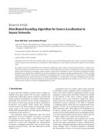
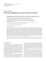
In a VSN, each vehicle is responsible for sensing one or
more events, routing messages to other vehicles or roadside base stations, and processing sensed data. As shown in
Figure 1, there are some moving vehicles and communication devices serving as base stations installed along the roads.
For that, car safety can be protected by early broadcasting to
police or neighbor cars as accidents occur. Then, a VSN is
also able to forward these accident information related to car
condition directly to roadside base stations or distant police
or emergency centers so that they can make necessary emergency response and medical treatment decisions as soon as
possible [4]. Moreover, the roadside base stations broadcast
or multicast it to neighbor cars to avoid more accidents.
The VSN can be used in many cost-effective ways [4, 5]
to gather traffic information to better understand how traffic
knots, and point out the situation in order to reduce congestion, minimize emission, decrease fuel consumption, or foster traffic security. How vehicular ad hoc network (VANET)
built VSN by equipping vehicles with onboard sensor devices
has been introduced by [4, 5] (see Figure 1). The solution for
car safety communication in VSN is to use intervehicle communication (IVC) [6]. As the vehicles move along the road,
the propagation of the information should follow the same
one-dimensional movement. Another difference is related
to the fact that in case of IVC, all vehicles are moving and
their relative speed with respect to each other is very small,
resulting in stable wireless links between vehicles. US FCC
has allocated a block of spectrum from 5.85 to 5.925 GHz
band for IVC and vehicle-to-road communications (VRCs)
that can support a wide range of applications [7]. One combined vehicular communication [7] is built with IVC, cellular
2
EURASIP Journal on Wireless Communications and Networking
Roadside base station
VSN-enabled vehicle
Systems
Sensors
Vehicle-to-roadside
communication (VRC)
Intervehicle
communication (IVC)
c
Video Chem. Storage Proc.
Figure 1: Vehicular sensor networks.
networks, and satellite networks (see Figure 2). Unlike IVC,
vehicular communication enables necessary information to
be uploaded and downloaded independently of space headway which is the space between moving vehicles, ships, or
targets.
Since vehicles travel at a higher speed, [8] designs a vehicular mesh (VMesh) network, which is an ad-hoc network
or a traditional wireless sensor network with no centralized
authority or infrastructure, to accomplish reliable data transit. In this scheme, mobile nodes can move, be added, or be
deleted as the network realigns itself. One of the benefits of a
mesh network is that it has the abilities of self-forming, selfhealing, and self-balancing. As shown in Figure 3, one of the
applications of using VMesh as a transit network is to establish connections between disjoint sensor networks.
Nowadays, the rapid deployment of network infrastructures in various environments triggers new applications and
services that in turn generate new constraints. For example,
heterogeneous networks will integrate ad hoc and sensor solutions into wired and/or wireless fixed infrastructures in future. The integration of ad hoc and sensor networks with
the Internet and wireless infrastructure networks increases
network capacity, coverage area, and application domains.
In this paper, we attempt to combine these heterogeneous
networks with vehicular sensor networks (VSNs), vehicular mesh networks (Vmeshs), and other existing networks.
While the interconnection of these networks must ensure
transport traffic between a source and a destination, it must
also keep on providing service of a very high quality and
make various flows safe and secure. Carrying out these challenges requires the modification and/or the adaptation of
some protocols.
Data center
Additional media such as existing network and VRC
Cellular networks
and satellite
networks
No IVC
IVC
IVC
Figure 2: A combined network.
Sensor
network A
Sensor
network C
Sensor
network B
Figure 3: Using VMesh to connect disjoint sensor networks.
Y.-F. Wang and L.-L. Liu
For safer and more reliable data transmission on VSN,
ensuring more stable and robust communication link is more
important than saving energy and decreasing communication costs, especially for emergency relief service in police
centers and traffic control. Therefore, we propose a simple
target-tracking algorithm that detects and tracks moving vehicles, and alerts them when they move beyond the safety
range. The moving target-tracking scheme is broadly applied in many areas, such as aeronautical systems, antimissile,
satellite manipulation, videoconferencing, and autonomous
mobile robots [9, 10]. In addition to the sensory detection
module [6], there are two major issues in a general positionbased tracking system. One is the estimation/prediction of
the target position from noisy sensory measurements and the
other is the motion control of the tracker to track the moving
target.
For some vehicles or fast movable ad hoc sensor networks, the mobility on VSN may frequently result in link failure. The failure protection becomes an essential challenge.
Since sensor malfunction is caused by broken links or weak
links, the system builds up protection and rerouting or selfhealing scheme to avoid link failure of networks. However,
as multiple sinks or cluster head paths build in a VSN, either
simple or single link broken will cause tremendous damage
to the working and maintenance of the VSN. Meanwhile, it
is necessary to enhance the system prediction capability to
avoid frequent failure for moving vehicles.
Greater mobility increases the volume of controlled traffic required to maintain broken routes. Some crucial ondemand mechanisms for minimizing broken links are provided to ensure rerouting responsiveness and efficiency on
on-demand manner [11, 12]. Because each vehicle moves
with different mobilities, the links are thus unstable or weak.
Since topology has changed fast and frequently on wireless
vehicular sensor networks, this motivates us to develop a
scheme for preventing or reducing network errors. In this paper, we propose and investigate a grey target-tracking resilient
routing (GTTRR) protocol for vehicular sensor networks to
prevent network failure caused by failed or weak links. We
apply a grey target-tracking strategy to track the moving target and self-heal or reroute in advance some weak links before link failure occurs. It makes routing decision with grey
predict system [13, 14] because the grey system only needs
a few data to perform tracking with high accuracy. It is very
suitable for real-time processing requirement. The simulation of the proposed scheme shows that the links become
more reliable since rerouting strategy starts before any network link becomes weaker. In this paper, Section 2 presents
the target tracking with grey system. Section 3 shows the simulation model and the results. Finally, a conclusion is given.
2.
3
many tracking systems use intelligent strategies to predict the
potential position of the object ahead at the next time period. The predicted result serves two purposes [10], one is for
the object (target) detection module to speed up the detection using inverse coordinate transformation, and the other
is for the motion control module to decide motion parameters. Once the accurate pose of object has been predicted,
the tracking system can then be performed. In a robot soccer game, the controller of the visual tracking system usually
monitors the pan and tilt angular velocities of the platform
to which a camera is attached; and for autonomous mobile
robots, the driving and steering velocities are employed to
follow a moving object (moving ball in a robot soccer game).
Most of the existing approaches to target tracking need a
prior dynamics model of target for prediction. In many cases,
the addition of the exact dynamic models is either difficult to
obtain or needs complex mathematical descriptions, such as
a walking human and robot soccer games [9]. Some algorithms proposed for target position predictions involve calculating the position, velocity, and acceleration of the moving targets from sensory measurements. The target motion
trend can be predicted according to a polynomial description that fits the past trajectory [15, 16]. Owing to the sensor
characteristics and the sampling rate of digital information,
the measured target trajectory data are usually not accurate
enough for prediction purpose. Therefore, a prior tracking
scheme using grey prediction to deal with the problem of dynamic and complex computation was proposed in this paper.
In a VSN, the wireless vehicles can configure themselves
to form a communication infrastructure so that sensed data
can be transmitted across the vehicles hop by hop. After the
mission of a sensor node is updated, it monitors the interest
of user and reports data when an interesting phenomenon
appears. We term a sensor node that has data to report as the
source and those that collect data as sinks [6, 12]. A sink collects reported information and sends it back to the user. The
sink node functions like a cell center, cluster head, gateway,
or base station.
Sometimes the sink broadcasts (one-to-many) the interests to all sensor nodes in the network. Each sensor node
stores the interest in a local cache and uses the gradient fields
within the interest descriptors to identify the most suitable
path to the sink. These paths are then used by source nodes to
communicate the sensed data to the sink [12, 17] like a structure of multicast trees. In VSN, multicast trees with memberships, joints, and leaves are likely to be frequently occurring,
especially for situations when the group is short-lived for distribution of a query or a short notification. Moreover, a more
frequent occurrence is actually the opposite problem, clustering (many-to-one) communication, when several sources of
data stream to the same sink [12].
GREY TARGET-TRACKING RESILIENT ROUTING
2.1.
If the sensor in the vehicle has a fast response time, it is possible to estimate the current pose of the vehicle and to support
real-time tracking performance. On the contrary, if the sensor has a slow response time, the estimation is no longer sufficient for a real-time tracking system [15]. For these reasons,
Grey system
Our proposed scheme applies the grey system to target tracking on VSN. The grey system was created and developed
by Deng in 1988 [13], and the most amazing aspect of the
grey theory is that the estimation is still valid under high
4
EURASIP Journal on Wireless Communications and Networking
X (1) (k)
X (0) (k)
AGO
X (1) (k + 1)
GM(1,1)
X (0) (k + 1)
IAGO
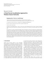
Figure 4: The procedure of simple grey prediction.
(0)
(1)
Xm (k)
X (0) (k)
MGO
(1)
Xm (k)
AGO
(0)
Xm (k + 1)
GM(1,1)
Xm (k + 1)
IAGO
IMGO
X (0) (k + 1)
Figure 5: The procedure of grey prediction with MGO.
uncertainty with only limited sampled data [13] (only four
data). The grey theory is developed from the grey exponential law. The procedures of the GM(1,1) model, AGO, and
MGO are described in detail in the appendix.
Simply, we can present the entire procedure as
x(0) = IAGO • GM(1, 1) • AGO • x(0),
x(0) : raw data sequence,
x(0) : predictive data sequence.
(1)
A predicted value can be obtained by inverse transform. The
accuracy of such a prediction certainly depends on the characteristics of the system [13]. If we have used MGO, we have
to use another presentation as follows:
x(0) = IMGO • IAGO • GM(1, 1) • AGO • MGO • x(0).
(2)
In particular, grey prediction accepts that the internal
structure, parameters, and characteristics of the observed
system are unknown. When making grey prediction, it is not
clear to find the trend of a nonnegative sequence with arbitrary distribution. However, if we accumulate the sequence,
we will get a monotonically nondecreasing sequence. Then,
with the grey exponential law, an optimum exponential curve
can be obtained to fit this sequence. The block diagram of a
grey predictor is shown in Figures 4 and 5. The flowchart of
grey model construction is shown in Figure 6.
2.2. Tracking moving target
A simple algorithm that detects and tracks a moving target
and alerts sensor nodes along the projected path of the target is developed in [18]. The algorithm involves only simple computation and localizes communication only to the
nodes in the vicinity of the target and its projected course.
In order to be energy efficient, the system must leverage data
processing and decision-making ability inside the network as
much as possible. This is because with today’s technology, the
power budget for communication is many times more than
that for computation. The goal is to track and predict the
movement of an appropriate target and alert the sensors that
are close to the predicted path of the target. The target can
be a moving vehicle, for example, or can be a phenomenon
such as an approaching fire. It is assumed that each individual sensor node (cluster head) is equipped with appropriate
sensory device(s) to be able to detect the target as well as to
estimate its distance from the sensed data. The sensors (cluster heads) that are triggered by the target collaborate to localize the target in the physical space to predict its course.
Tracking a target involves three distinct steps [18] described
as follows:
(1) detecting the presence of target,
(2) determining the direction of motion of target,
(3) alerting appropriate nodes in the network.
In this paper, we employ the grey prediction system to replace estimation in the tracking step and improve the function of data transmission in the alerting step. The most amazing aspect of the grey theory is that the estimation is still valid
under high uncertainty with only limited sampled data (only
four data). Predicting the location of the object (vehicle) is a
common mean for tracking a moving object (vehicle). Grey
prediction assumes that the internal structure, parameters,
and characteristics of the observed system are unknown. It
attempts to establish a grey model from the recent historical
measurements of the external motion (the value of the last
four data) for obtaining the predicted value.
In tracking steps, grey prediction will decrease the times
required for estimation because linear regression need not
be performed. In alerting step, we send warning message
when moving targets (vehicles) move out of the transmission threshold or when the link between vehicle-vehicle or
vehicle-cluster head is weak, and protect the weak link by
rerouting in advance.
The process of the path discovery [19, 20] is initiated
whenever a source node (vehicle) needs to communicate
with another node or link weakness is sensed for which it
has no routing information in its table. Every sensor node
maintains two separate counters: a node sequence number
and a broadcast id. The source node initiates path discovery
by broadcasting a route request (RREQ) packet to its neighbors [19, 20].
Most reactive routing protocols, such as AODV and DSR,
have similar route discovery mechanisms [19, 20]. In this
paper, we adopt a similar route discovery method. Figure 7
shows an example of route discovery [19, 20], in which a
Y.-F. Wang and L.-L. Liu
5
T
Give original data sequence
x(0) = (x(0) (1), x(0) (2), x(0) (3), · · · , x(0) (n)), ∀n ≥ 4
P
Q
S
Get first-order AGO sequence
k
id = 3
x(0) (i)
x(1) (k) = AGO x(0) (k) =
“S”
W
R
“S, R”
id = 3
U
“S, R, U”
id = 3
V
“S, R, U, V”
id = 3
X
i=1
RREQ
RREP
Find the background value Z (1) (k)
Z (1) (k) = 0.5 x(1) (k) + x(1) (k − 1) , k ≥ 2
1. Use least-square method to find matrix B and vector yn
2. Find a and b
n
a=
k=2
z(1) (k)
n
x(0) (k) − (n − 1)
k=2
n
z(1) (k)
(n − 1)
2
b=
k=2
[z(1) (k)]2
z(1) (k)x(0) (k)
k=2
n
2
z(1) (k)
−
k=2
n
n
k=2
n
x(0) (k) −
k=2
n
z(1) (k)
k=2
n
(n − 1)
k=2
[z(1) (k)]2 −
n
z(1) (k)x(0) (k)
k=2
n
2
z(1) (k)
k=2
Get the response equation (whitening):
b −ak b
x(1) (k + 1) = x(0) (1) −
e
+ , k = 1, 2, · · · , n
a
a
Get the predictive result x(0) (k + 1) by IAGO
b −ak
x(0) (k + 1) = 1 − ea x(0) (1) −
e
a
(0) (k + 1) = x (1) (k + 1) − x (1) (k), k = 1, 2, · · · , n
x
Figure 6: The flowchart of grey model construction.
node S (source or initiator) attempts to discover a route to
node X (destination or target). To initiate route discovery,
S transmits a route request (RREQ) message as a single local broadcast packet, which is received by all nodes currently
within the wireless transmission range of S. Each RREQ message identifies the initiator and target of the route discovery,
and contains a unique request id (here, id = 3), determined
by the initiator of the request. Each RREQ also contains a
record listing the address of each intermediate node through
which this particular copy of the RREQ message has been forwarded. This route record is initialized to an empty list by the
Figure 7: On-demand routing protocol route discovery (S: initiator; X: target).
initiator of the route discovery. When another node receives
an RREQ, if it is the target of the route discovery, it returns a
route reply (RREP) message to the initiator of the route discovery, giving a copy of the accumulated route record from
the RREQ; when the initiator receives this RREP, it caches
this route in its route cache for use in sending subsequent
packets to this destination. Otherwise, if this node receiving
the RREQ has recently seen another RREQ message from this
initiator bearing this same request id, or if it finds that its own
address is already listed in the route record in the RREQ message, it discards the request. Otherwise, this node appends its
own address to the route record in the RREQ message and
propagates it by transmitting it as a local broadcast packet
(with the same request id).
To return the RREP to the initiator of the route discovery, node X will typically examine its own route cache for
a route back to S, and if found, will use it for the source
route for delivering the packet containing the RREP. Otherwise, X may perform its own route discovery for target
node S; but to avoid possible infinite recursion of route
discoveries, it must piggyback this RREP on its own RREQ
message for S. Node X could also simply reverse the sequence
of hops in the route record that it is trying to send in the
RREP, and use this as the source route on the packet carrying the RREP itself. The RREQ contains the following fields:
source
addr
broadsource
dest
hop
cast id,
sequence#
sequence# cnt
dest addr
signal
strength
The pair source addr, broadcast id identifies uniquely
an RREQ. Broadcast id is incremented whenever the source
issues a new RREQ. Each neighbor either satisfies the RREQ
by sending a route reply (RREP) back to the source, or rebroadcasts the RREQ to its own neighbors after increasing
the hop cnt. Figure 8 represents the forward path setup as
the RREP travels from the destination node D to the source
node S. Note that it will timeout after three seconds and
will delete the reverse pointers, and that a node may receive multiple copies of the same route broadcast packet
from various neighbors. The signal strength has two roles:
one as the parameter for selecting destination path and the
6
EURASIP Journal on Wireless Communications and Networking
other as the power strength indicator between vehicle and
vehicle or cluster head. When an intermediate node (vehicle or cluster head) receives an RREQ, if it has already
received an RREQ with the same broadcast id and source
address, it drops the redundant RREQ and does not rebroadcast it. If a node cannot satisfy the RREQ, it keeps
track of the following information in order to implement
the reverse path setup, as well as the forward path setup
that will accompany the transmission of the eventual RREP:
dest
sequence#
hop
cnt
life
time
A node receiving an RREP propagates the first RREP for
a given source node towards that source. If it receives further
RREPs, it updates its routing information and propagates the
RREP only if the RREP contains either a greater number of
destination sequences than the previous RREP, or the same
number of destination sequences with a smaller hop count.
It suppresses all other RREPs it receives. This decreases the
number of RREPs propagating towards the source while also
ensuring the most up-to-date and quickest routing information. The source node can begin data transmission as soon
as the first RREP is received, and can later update its routing
information if it learns of a better route.
Whether rerouting will be performed in advance is decided according to the predictive power value the vehicle received (it denotes the distance or signal strength) from cluster head, the current received power value (x(0) (k)) and three
historical received values (x(0) (k − 1), x(0) (k − 2), x(0) (k − 3)).
To avoid unnecessary calculations of grey prediction, we
set a prediction range of 200 m, which is a safe range from the
transmitter. Hereafter, the following parameters are defined
in the grey prediction algorithm [21, 22].
(1) PowerReceived (k), Pr : signal strength between two
communicating nodes. (k represents the relative sequence received from the transmitter or intermediator.)
(2) ReceiveThreshold Tr : signal strength for starting grey
prediction (set the start grey prediction for 200 m).
(3) SafeThreshold Ts : signal strength for unsafe alarming
(set it for 240 m).
(4) DisconnectThreshold Td : signal strength for disconnection range (set the largest transmission for 250 m)
[4, 5, 23].
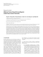
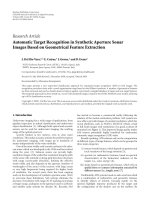
As the other prerouting scheme in [24], Figure 9 demonstrates the preemptive mechanism around a source. For example, when node C moves to SafeThreshold 240 m (as
node C4 ), the grey prediction will initiate to find the vicinal nodes (node D) and the link of communication remains
unchanged. When node C4 moves into range 240–250 m (as
node Cn ), the signal power of received packets from source
node A falls below the SafeThreshold (distance greater than
240 m), generating a warning packet to node A. Then, node
A initiates route discovery action and can discover fast a new
route through node D (because of grey prediction). Hereafter, it switches to this route to avoid failure of the path. Even
if node Cn moves out of the radio range of source node A
S
Timeout
Figure 8: Reverse path formation.
B
sa
f
ra e tra
ng n
e sm
iss
io
n
dest
addr
Cm Cn C4
C3
C2
C1
24
0m
source
addr
D
C
A
D
es s a r y
e
unnec
00 m iction rang
2
pred
250
m
r ad
io
ran
ge
Figure 9: Preemptive mechanism and various ranges.
(like node Cm ), the new route path still works by forwarding
data to node D.
By applying signal strength to GM(1,1), we developed a
grey prediction algorithm (Algorithm 1) [21, 22].
Since an explicit estimate of the preemptive range requires the nodes to exchange location and velocity information, we use the signal power [25] of received packets
to estimate the distance between them. The recovery time
can be related to the power threshold as follows. The signal
power drops such that at a distance r from the transmitter,
the signal power at any point is the sum of the main signals transmitted by the antenna in addition to components
of the signal that reflect off the surrounding features (multipath effect). In an open environment, the main secondary
Y.-F. Wang and L.-L. Liu
7
input PowerReceived(k){
if PowerReceived (k) ReceiveThreshold {
//distance (k) 200 m
if (k 4){
generate grey prediction value PowerReceived (x(0) (k + 1));
if PowerReceived (x(0) (k + 1)) < SafeThreshold {
then do alerting and prerouting ;}
//ditance 240 m
else k++ ;}
//distance < 200 m does not use grey prediction to reduce load
else x = 0 ;}
}
Algorithm 1: Procedure of GTTRR algorithm.
component is the strong reflection of the transmitted signal
from the ground. Hence power strength is a value approximated by Pr = P0 (d/d0 )−ne , where P0 is the power received at
the close-in reference point in the far-field region of the antenna at small distance d0 from the transmitting antenna and
ne is the path loss exponent. Since the energy decay between
two nodes is inversely proportional to the distance separating
them, we set the path loss exponent ne to be 4 in our simulation (discussed in Section 3) as follows:
Pr =
Po
.
rn
(3)
We summarize the GTTRR procedure as follows:
(1) making detection,
(2) clustering for energy efficiency [12],
(3) tracking with grey system:
(3-1) use the k (four historical) data received from the
transmitter range value between two communicating nodes to construct a GM(1,1) [13, 26]
model,
(3-2) use the GM(1,1) model to predict (x(0) (k + 1)).
The predicted value is noted as (x(0) (k + 1)),
(4) alerting: if (x(0) (k + 1)) ≥ Tr (Ts is a prerouting
SafeThreshold at 240 m), broadcast warning message
and generate a rerouted call packet broadcast to cluster
head or sink,
(5) rerouting: cluster head or sink broadcasts a route request (RREQ) packet to its neighbors and self-heals or
reroutes the weak or broken link.
For multicast rerouting of multiple sinks, GTTRR applies
the grey prediction system to predict the weak links of multicast trees and reroutes them in advance. If the upper stream
path does not fail, it continues to receive data of the multicast tree, until the link breaks or a new path is found. There
are two multicasting schemes applied in this paper: MAODV
(tree-based) [27] and ODMRP (mesh-based) [23].
3.
SIMULATIONS AND ANALYSIS
In order to verify the characteristics of the proposed schemes,
we developed a network model to evaluate rerouting performance on multicast VSN. The simulated screens were
Figure 10: Simulations for multicast.
shown in Figure 10 [21, 22]. The parameters of the simulation model were assumed as below. Simulation was performed in a square area of 1000 m × 1000 m with 30, 40, and
50 mobile nodes (vehicles). The radio transmission range of
vehicle is 250 m [4, 5, 23]. For each ten milliseconds, one
of the 10 multicast member groups is randomly changed.
The channel traffic is set to be four packets per second [28].
The processing time for receiving and sending out message
is three milliseconds (one hop delay time). The working and
spare capacities are set to be enough for all calls. The mobility speed is set at the range of 40 km/h to 110 km/h (urban
area: 10 m/s; highway: 30 m/s [7]). The total simulation time
of each pattern is 1200 seconds. In the simulation, we adopt
both MAODV and ODMRP with grey prediction (GTTRR)
to compare their efficiencies (we make a summary of the parameters in Table 1).
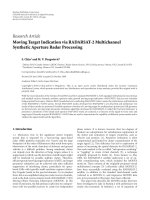
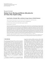
Figure 11 (50 nodes), Figure 12 (40 nodes), and Figure 13
(30 nodes) show different packet delivery ratios with mobility speeds. Respectively, as speed increases, the routing
8
EURASIP Journal on Wireless Communications and Networking
Table 1: Simulation parameters.
Parameter
Value
Simulation terrain
1000 m × 1000 m [4, 23]
Simulation time
1200 seconds
Number of nodes (density)
50 [23], 40, and 30 mobile vehicles
Disconnet Threshold T d
Signal strength (dBm) at 250 m [4, 5, 23]
Receive Threshold Tr
Signal strength (dBm) at 200 m
Safe Threshold Ts
Signal strength (dBm) at 240 m
Vehicular speed range
40 km/h ∼ 110 km/h [7]
Routing protocol
MAODV; ODMRP [23, 27]
Moving direction
Changed by random
(9 directions are randomly selected)
Path loss exponent
4
Data-sending rate
4 packets/s [28]
100
Packet delivery ratio (30 nodes) (%)
Packet delivery ratio (50 nodes) (%)
100
90
80
70
60
50
40
30
20
40
50
60
70
80
Speed (km/h)
90
100
110
MAODV
MAODV GP
ODMRP
ODMRP GP
Packet delivery ratio (40 nodes) (%)
100
90
80
70
60
50
40
30
40
50
60
ODMRP
ODMRP GP
70
80
Speed (km/h)
90
80
70
60
50
40
30
20
40
50
60
ODMRP
ODMRP GP
Figure 11: Packet delivery ratio versus mobility speed (50 nodes).
20
90
100
110
MAODV
MAODV GP
Figure 12: Packet delivery ratio versus mobility speed (40 nodes).
70
80
Speed (km/h)
90
100
110
MAODV
MAODV GP
Figure 13: Packet delivery ratio versus mobility speed (30 nodes).
efficiency of the packet delivery ratio degrades rapidly. However, ODMRP-GP has the best performance since there are
more redundant routes in the mesh structure. With increasing number of nodes in the topology, the density of the system user dispersion becomes higher. It affects the packet delivery ratio: the larger the number of nodes is, the larger the
connection probability it gets. In other words, the packet delivery ratio is proportional to the density of nodes.
Figure 14 (50 nodes), Figure 15 (40 nodes), and Figure 16
(30 nodes) show the average throughput, respectively, as a
function of multicast with grey prediction (GP) as speed
increases. In this paper, we term throughput as the total
amount of packets (data and control packets) transferred
from one node (source) to another (receiver) and processed
in a specified amount of time. As can be seen, ODMRP has
higher throughput, and grey prediction makes the throughput of both multicast schemes better. In this paper, the
ODMRP has a set mesh-based topology. As we know, the
Y.-F. Wang and L.-L. Liu
9
1800
4000
1600
Control overhead (50 nodes)
Throughput (50 nodes)
4500
3500
3000
2500
2000
1500
1000
40
50
60
70
80
Speed (km/h)
90
100
110
1400
1200
1000
800
600
400
200
40
50
60
MAODV
MAODV GP
ODMRP
ODMRP GP
70
80
Speed (km/h)
100
110
MAODV
MAODV GP
ODMRP
ODMRP GP
Figure 14: Throughput versus mobility speed (50 nodes).
90
Figure 17: Control overhead versus mobility speed (50 nodes).
4500
Control overhead (40 nodes)
1800
Throughput (40 nodes)
4000
3500
3000
2500
2000
1500
1000
40
1600
1400
1200
1000
800
600
400
40
50
60
70
80
Speed (km/h)
90
100
60
ODMRP
ODMRP GP
MAODV
MAODV GP
ODMRP
ODMRP GP
50
110
70
80
Speed (km/h)
90
100
110
MAODV
MAODV GP
Figure 18: Control overhead versus mobility speed (40 nodes).
Figure 15: Throughput versus mobility speed (40 nodes).
Throughput (30 nodes)
4500
4000
3500
3000
2500
2000
1500
1000
40
50
60
ODMRP
ODMRP GP
70
80
Speed (km/h)
90
100
MAODV
MAODV GP
Figure 16: Throughput versus mobility speed (30 nodes).
110
mesh conveniently provides alternate paths in failure, thus
making better the ODMRP throughput. According to our
definitions, the throughput and packet delivery ratio have
the same trend. Although ODMRP-GP has the best performance, both MAODV and ODMRP have fewer variations.
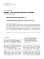
Figures 17, 18, and 19 show the control overhead on
multicast node densities 50, 40, and 30, respectively. In
these three figures, ODMRP has less control overhead than
MAODV. One of the reasons is that MAODV has more forward nodes to transmit data and control signals in multicast.
Moreover, both MAODV-GP and ODMRP-GP need more
control overhead to make the path stable when grey prediction is used. The figure shows if they use grey prediction
scheme to improve their data transmission, they need twice
above control overheads.
Figures 20, 21, and 22 show the end-to-end delay on multicast node densities 50, 40, and 30, respectively. In multicast, each member does not receive data from the same forwarder; therefore, we calculate the average end-to-end delay
EURASIP Journal on Wireless Communications and Networking
End-to-end delay (ms, 30 nodes)
Control overhead (30 nodes)
10
1800
1600
1400
1200
1000
800
600
400
40
50
60
70
80
Speed (km/h)
90
100
110
30
25
20
15
10
5
MAODV
MAODV GP
ODMRP
ODMRP GP
35
40
50
60
ODMRP
ODMRP GP
70
80
Speed (km/h)
90
100
110
MAODV
MAODV GP
Figure 19: Control overhead versus mobility speed (30 nodes).
Figure 22: End-to-end delay versus mobility speed (30 nodes).
End-to-end delay (50 nodes)
35
30
25
20
15
10
5
40
50
60
70
80
Speed (km/h)
90
100
110
MAODV
MAODV GP
ODMRP
ODMRP GP
End-to-end delay (40 nodes)
Figure 20: End-to-end delay versus mobility speed (50 nodes).
35
30
25
20
15
10
5
40
50
60
ODMRP
ODMRP GP
70
80
Speed (km/h)
90
100
110
MAODV
MAODV GP
Figure 21: End-to-end delay versus mobility speed (40 nodes).
time from the source. In addition, the end-to-end delay of
the dropped packets has an infinite delay; hence, we do not
include it in the calculation.
As shown in the simulated results, the end-to-end delay did not show obvious difference with increasing mobility
speed. Both ODMRP and ODMRP-GP have longer delay
time than MAODV and MAODV-GP. However, the number
of nodes on the topology is affected seriously. The more the
number of nodes is, the more the intermediated nodes are
contained. More nodes require more processing time and increase in the end-to-end delay. The higher the node density
is, the longer the end-to-end delay is required.
Tables 2, 3, and 4 show the average performance of different node densities versus different routing protocols, respectively. They demonstrate the average performance against
packet delivery ratio, throughput, overhead, and end-to-end
delay for multicast on VSN. Because combined networks can
use multicast trees and meshes to transmit data, the number
of broken paths and robustness are not suitable according
to the comparison. For packet delivery ratio and throughput on multicast, MAODV-GP and ODMRP-GP are better
than MAODV and ODMRP since the prediction mechanism
is applied. However, in terms of overhead, MAODV-GP and
ODMRP-GP are worse than MAODV and ODMRP. The reason is that the grey system uses more overhead to protect
and maintain the communication paths. For end-to-end delay, unfortunately, the grey prediction does not have obvious
function to improve their delay.
Finally, for node density, we accumulate the total of the
above three tables to find the different performances as integrated in Table 5. The higher the node density is, the more
the control overhead is required. Moreover, higher node density means better packet delivery ratio and throughput. On
the contrary, the higher the node density is, the longer the
end-to-end delay is.
4.
CONCLUSION
Wireless VSN has enough processing and storage to handle
the data collected before. In traditional static sensor network,
Y.-F. Wang and L.-L. Liu
11
Table 2: Average performances for multicast (50 nodes).
Routing protocol
Packet delivery ratio
Throughput (total)
Control overhead
End-to-end (ms)
MAODV
MAODV-GP
ODMRP
ODMRP-GP
41.36%
46.23%
50.92%
68.56%
1985.625
2219.25
2444.25
3291
528
1451
444
1209
11.9025
11.02875
26.745
27.5125
Total
207.07%
9940.125
3632
77.18875
Table 3: Average performances for multicast (40 nodes).
Routing protocol
Packet delivery ratio
Throughput (total)
Control overhead
End-to-end (ms)
MAODV
MAODV-GP
ODMRP
ODMRP-GP
41.34%
47.21%
47.96%
63.57%
1984.125
2266.25
2302
3051.5
605.125
1520.375
547.875
1381.125
11.35625
9.845
22.31
22.8475
Total
200.08%
9603.875
4054.5
66.35875
sensor data are usually pulled by the sink. When a vehicle
moves at a high speed, it will damage the link or cause sinktree failure. So the activation of the wireless links and such
frequent changes in location in the network topology limit
transmission range and challenge significantly the survivable
operations in the vehicular sensor networks. Therefore, survivable sink multicasting and rerouting in advance becomes
an important issue nowadays.
In this paper, we propose a GTTRR scheme to self-heal or
reroute weak links before they are broken. Moreover, we expand the traditional multicasting joining both ODMRP and
MAODV with grey prediction rerouting in advance to enhance the quality of multicasting wireless onvehicular sensor
networks.
For performance evaluation, we simulate multicasting
mobile capabilities on two routing schemes: ODMRP and
MAODV. MAODV has more multiforwarders than ODMRP.
The receivers of multicasting can receive the data from more
sources, and MAODV requires more overhead for maintaining the connection paths. Nevertheless, MAODV can support the unicasting at the same time but ODMRP cannot. By
selecting suitable parameters and joining with grey prediction, MADOV can obviously decrease the number of broken
links and reduce the dissipation of power.
GTTRR on target tracking makes the whole wireless VSN
more stable, although it increases average latency and control overhead. However, it supports higher survivability and
effective reflections on rerouting.
ation, grey differential equation modeling, whitening equation for prediction, and inverse accumulated generating operation (IAGO). The GM(1,1) model is the most commonly
used model. The first 1 in GM(1,1) means that there is only
one variable, and the other 1 means that the first-order grey
differential equation is employed to construct the model.
The procedure of GM(1,1) model for predicting the value of
x(0) (k + 1) is described as follows.
Herein, we let x(0) be the nonnegative original data sequence and denote it as
x(0) = x(0) (1), x(0) (2), . . . , x(0) (n) ,
A.1.
Construction of grey prediction model GM(1,1)
Grey prediction using grey model (GM) involves five operations: accumulated generating operation (AGO), mean oper-
(A.1)
where n is the sampling size of the recorded data.
Moreover, the first-order differential grey model
GM(1,1) is
dx(1)
+ ax(1) = b,
dt
(A.2)
where a is the “develop parameter” and b is the “grey input.”
The first derivative of AGO sequence x(1) becomes
dx(1)
= x(1) (k) − x(1) (k − 1) = x(0) (k),
dt
(A.3)
where k = 2, 3, . . . , n and let z(1) (k) be the average of x(1) (k)
and x(1) (k − 1),
Z (1) (k) = 0.5 x(1) (k) + x(1) (k − 1)],
APPENDIX
∀n ≥ 4,
k ≥ 2.
(A.4)
In the grey system, we always set factor α to be 0.5; hence,
the original intact expression can be shown as
Z (1) (k) = α · x(1) (k) + (1 − α) · x(1) (k − 1),
k ≥ 2.
(A.5)
12
EURASIP Journal on Wireless Communications and Networking
Table 4: Average performances for multicast (30 nodes).
Routing protocol
Packet delivery ratio
Throughput (total)
Control overhead
End-to-end (ms)
MAODV
MAODV-GP
ODMRP
ODMRP-GP
40.36%
44.77%
43.89%
51.18%
1937.25
2148.875
2106.5
2456.625
678.625
1578.375
665.875
1525.5
8.9925
8.47125
16.1425
17.275
Total
180.20%
8649.25
4448.375
50.88125
Table 5: Total value for different nodes density.
Nodes density
Packet delivery ratio
Throughput (total)
Control overhead
End-to-end(ms)
50
40
30
207.07%
200.08%
180.20%
9940.125
9603.875
8649.25
3632
4054.5
4448.375
77.18875
66.35875
50.88125
Next, we approximate the second term of (A.2) and (A.4)
and substitute it into (A.3). Then, the first-order grey differential model is established as
x(0) (k) + aZ (1) (k) = b, k = 1, 2, 3, . . . , n,
a
x(0) (k) = b − x(1) (k) + x(1) (k − 1) .
2
The completed grey procedure is as follows.
(A.6)
k
x(0) (i),
(A.7)
i=1
and the rth-order AGO is defined as
k
x(r) (k) =
x(r −1) (m),
a = [a, b]T = BT B
−1
B T yn ,
(A.12)
where
a=
Step 1. Find the first-order AGO sequence by taking AGO on
x(0) and denote it as
x(1) (k) = AGO x(0) (k) =
Step 4. Parameters a and b can be obtained by the following
operation:
n
(1)
k=2 z (k)
(n − 1)
n
n
(0)
(1)
(0)
k=2 x (k) − (n − 1) k=2 z (k)x (k)
,
2
2
n
n
(1)
(1)
k=2 z (k) −
k=2 z (k)
b=
n
k=2
2
z(1) (k) n=2 x(0) (k) − n=2 z(1) (k) n=2 z(1) (k)x(0) (k)
k
k
k
.
2
2
(n − 1) n=2 z(1) (k) − n=2 z(1) (k)
k
k
(A.13)
Step 5. Get the response (whitening) equation
k = 1, 2, 3, . . . , n,
m=1
(A.8)
x(r) (k) = x(r) (k − 1) + x(r −1) (k).
Step 2. As described above, find the background value
Z (1) (k) using the mean operation from x(1) (k) and x(1) (k − 1),
b −ak b
e + ,
a
a
x(1) (1) = x(0) (1),
x(1) (k + 1) = x(0) (1) −
k = 1, 2, . . . , n,
(A.14)
(A.9)
where x(1) (k + 1) is the solution of the whitening equation
(A.2) or (A.6), and k represents the grey prediction step.
From the background value Z (1) (k), GM(1,1) first-order
whitening differential equation can be constructed as
Step 6. Get the forecasting (prediction) value x(0) (k + 1) by
inversing AGO (IAGO) back to the original data sequence:
(1)
(1)
(1)
Z (k) = 0.5 x (k) + x (k − 1) ,
k ≥ 2.
dx(1) (k)
(A.10)
+ aZ (1) (k) = b.
dk
Step 3. Use least-square method to find matrix B and vector
yn :
⎡
−Z(1) (2) 1
⎢ (1)
⎢−Z (3)
⎢
B=⎢
.
⎢
.
.
⎣
(1)
−Z (k)
⎤
⎥
1⎥
⎥
.⎥,
.⎥
.⎦
x(1) (1) = x(0) (1),
x(0) (k + 1) = x(1) (k + 1) − x(1) (k),
Sometimes (A.15) can be represented by
x(0) (k + 1) = 1 − ea
(A.11)
1
T
yn = x(0) (2), x(0) (3), x(0) (4), . . . , x(0) (n) .
k = 1, 2, . . . , n.
(A.15)
x(0) (1) −
b −ak
e ,
a
(A.16)
x(1) (1) = x(0) (1),
where x(0) (k + 1) is the prediction result for the next observation.
Y.-F. Wang and L.-L. Liu
A.2.
13
An example of MGO
For example, we assume that a data sequence f (0) includes
some negative data. We may give a positive reference parameter ε (always set to 1) to adapt the data sequence to nonnegative by bias function. The bias function is denoted as
n
bias = min f (0) (k) + ε,
k=1
(A.17)
and we usually let ε = 1. The MGO operation is expressed as
(0)
fm = MGO ◦ f (0) = f (0) + bias.
(A.18)
Example 1. If we have a sequence f (0) = {−1, −2, 1, 2}, we
can get the bias by (A.17),
n
bias = min f (0) (k) + ε = | − 2| + 1 = 3,
k=1
(A.19)
and we can transfer the nonnegative sequence by MGO operation:
(0)
fm = MGO ◦ f (0) = f (0) + bias = {2, 1, 4, 5}.
(A.20)
If the MGO operation is executed, the inverse operation
(IMGO) must be used and it is necessary to correct the predicted value. The inverse operation (IMGO) is as follows:
(0)
(0)
f (0) = IMGO ◦ fm = fm − bias,
(A.21)
where f means that its value is predicted by grey prediction.
REFERENCES
[1] B. Liu, P. Brass, O. Dousse, P. Nain, and D. Towsley, “Mobility improves coverage of sensor networks,” in Proceedings of
the 6th ACM International Symposium on Mobile Ad Hoc Networking and Computing (MobiHoc ’05), pp. 300–308, UrbanaChampaign, Ill, USA, May 2005.
[2] I. F. Akyildiz, W. Su, Y. Sankarasubramaniam, and E. Cayirci,
“A survey on sensor networks,” IEEE Communications Magazine, vol. 40, no. 8, pp. 102–114, 2002.
[3] D. Niculescu, “Communication paradigms for sensor networks,” IEEE Communications Magazine, vol. 43, no. 3, pp.
116–122, 2005.
[4] H. Alshaer and E. Horlait, “An optimized adaptive broadcast
scheme for inter-vehicle communication,” in Proceedings of the
61st IEEE Vehicular Technology Conference (VTC ’05), vol. 5,
pp. 2840–2844, Stockholm, Sweden, May-June 2005.
[5] U. Lee, E. Magistretti, B. Zhou, M. Gerla, P. Bellavista, and A.
Corradi, “MobEyes: smart mobs for urban monitoring with
vehicular sensor networks,” Tech. Rep. 060015, UCLA CSD,
Los Angeles, Calif, USA, 2006.
[6] M. Durresi, A. Durresi, and L. Barolli, “Sensor inter-vehicle
communication for safer highways,” in Proceedings of the 19th
International Conference on Advanced Information Networking
and Applications (AINA ’05), vol. 2, pp. 599–604, Taipei, Taiwan, March 2005.
[7] H. Saito, “Performance analysis of combined vehicular communication,” IEICE Transactions on Communications, vol. E89B, no. 5, pp. 1486–1494, 2006.
[8] H. C. Chang, H. Du, J. Anda, C.-N. Chuah, D. Ghosal, and H.
M. Zhang, “Enabling energy demand response with vehicular
mesh networks,” in Proceedings of the 6th IFIP IEEE International Conference on Mobile and Wireless Communication Networks (MWCN ’04), pp. 371–382, Paris, France, October 2004.
[9] C.-C. Wong, B.-C. Lin, and C.-T. Cheng, “Fuzzy tracking
method with a switching grey prediction for mobile robot,” in
Proceedings of the 10th IEEE International Conference on Fuzzy
Systems, vol. 1, pp. 103–106, Melbourne, Australia, December
2001.
[10] R. C. Luo and T. M. Chen, “Target tracking by grey prediction theory and look-ahead fuzzy logic control,” in Proceedings
of IEEE International Conference on Robotics and Automation,
vol. 2, pp. 1176–1181, Detroit, Mich, USA, May 1999.
[11] C. E. Perkins and E. M. Royer, “Ad-hoc on-demand distance
vector routing,” in Proceedings of the 2nd IEEE Workshop on
Mobile Computing Systems and Applications (WMCSA ’99), pp.
90–100, New Orleans, La, USA, February 1999.
[12] S. D. Muruganathan, D. C. F. Ma, R. I. Bhasin, and A. O. Fapojuwo, “A centralized energy-efficient routing protocol for wireless sensor networks,” IEEE Radio Communications Magazine,
vol. 43, no. 3, pp. 8–13, 2005.
[13] J. Deng, Essential Topics on Grey System: Theory and Application, China Ocean Press, Beijing, China, 1988.
[14] X. Wu, H. Heo, R. A. Shaikh, J. Cho, O. Chae, and S. Lee, “Individual contour extraction for robust wide area target tracking in visual sensor networks,” in Proceedings of the 9th IEEE
International Symposium on Object and Component-Oriented
Real-Time Distributed Computing (ISORC ’06), pp. 179–185,
Gyeongju, South Korea, April 2006.
[15] R. C. Luo, T. M. Chen, and K. L. Su, “Target tracking using hierarchical grey-fuzzy motion decision-making method,”
IEEE Transactions on Systems, Man, and Cybernetics—Part A,
vol. 31, no. 3, pp. 179–186, 2001.
[16] I. Pavlidis and N. P. Papanikolopoulos, “Automatic selection of
control points for deformable-model-based target tracking,”
in Proceedings IEEE International Conference on Robotics and
Automation, vol. 4, pp. 2915–2920, Minneapolis, Minn, USA,
April 1996.
[17] E. M. Royer and C. K. Toh, “A review of current routing protocols for ad hoc mobile wireless networks,” IEEE Personal Communications, vol. 6, no. 2, pp. 46–55, 1999.
[18] R. Gupta and S. R. Das, “Tracking moving targets in a smart
sensor network,” in Proceedings of the 58th IEEE Vehicular
Technology Conference (VTC ’03), vol. 5, pp. 3035–3039, Orlando, Fla, USA, October 2003.
[19] K. Sanzgiri, I. D. Chakeres, and E. M. Belding-Royer, “Prereply probe and route request tail: approaches for calculation
of intra-flow contention in multihop wireless networks,” Mobile Networks and Applications, vol. 11, no. 1, pp. 21–35, 2006.
[20] D. B. Johnson, D. A. Maltz, and J. Broch, “DSR: the dynamic source routing protocol for multi-hop wireless ad hoc
networks,” in Ad Hoc Networking, chapter 5, pp. 139–172,
Addison-Wesley, Reading, Mass, USA, 2001.
[21] Y.-F. Wang and L.-L. Liu, “Grey-based prerouting and target
tracking on vehicular sensor networks,” in Proceedings of the
National Symposium on Telecommunications (NST ’06), Kaohsiung, Taiwan, December 2006.
[22] Y.-F. Wang and L.-L. Liu, “Grey target tracking on vehicular
sensor networks,” in Proceedings of International Conference on
Late Advances in Networks (ICLAN ’06), Paris, France, December 2006.
14
EURASIP Journal on Wireless Communications and Networking
[23] S.-J. Lee, W. Su, and M. Gerla, “On-demand multicast routing
protocol in multihop wireless mobile networks,” Mobile Networks and Applications, vol. 7, no. 6, pp. 441–453, 2002.
[24] T. Goff, N. B. Abu-Ghazaleh, D. S. Phatak, and R. Kahvecioglu,
“Preemptive routing in ad hoc networks,” in Proceedings of
the 7th Annual International Conference on Mobile Computing
and Networking (MOBICOM ’01), pp. 43–52, Rome, Italy, July
2001.
[25] S. L. Su, Y. C. Su, and J. F. Huang, “Grey-based power control
for DS-CDMA cellular mobile systems,” IEEE Transactions on
Vehicular Technology, vol. 49, no. 6, pp. 2081–2088, 2000.
[26] X. Wang and X. Wu, “Application of grey system models to
rural economy analysis in China,” in Proceedings of the 1st International Conference on Uncertainty Modelling and Analysis,
pp. 511–516, College Park, Md, USA, December 1990.
[27] E. M. Royer and C. E. Perkins, “Multicast Ad Hoc on Demand Distance Vector (MAODV) routing,” IETF Internet
draft, draft-ietf-manet-maodv-00.txt, 2000.
[28] L. Qin and T. Kunz, “Pro-active route maintenance in DSR,”
ACM SIGMOBILE Mobile Computing and Communications
Review, vol. 6, no. 3, pp. 79–89, 2002.