Báo cáo hóa học: " Research Article Software-Controlled Dynamically Swappable Hardware Design in Partially Reconfigurable Systems" doc
Bạn đang xem bản rút gọn của tài liệu. Xem và tải ngay bản đầy đủ của tài liệu tại đây (816.45 KB, 11 trang )
Hindawi Publishing Corporation
EURASIP Journal on Embedded Systems
Volume 2008, Article ID 231940, 11 pages
doi:10.1155/2008/231940
Research Article
Software-Controlled Dynamically Swappable Hardware
Design in Partially Reconfigurable Systems
Chun-Hsian Huang and Pao-Ann Hsiung
Department of Computer Science and Information Engineering, National Chung Cheng University, Chiayi 621, Taiwan
Correspondence should be addressed to Pao-Ann Hsiung,
Received 24 May 2007; Accepted 15 October 2007
Recommended by Toomas P. Plaks
We propose two basic wrapper designs and an enhanced wrapper design for arbitrary digital hardware circuit designs such that
they can be enhanced with the capability for dynamic swapping controlled by software. A hardware design with either of the proposed wrappers can thus be swapped out of the partially reconfigurable logic at runtime in some intermediate state of computation
and then swapped in when required to continue from that state. The context data is saved to a buffer in the wrapper at interruptible
states, and then the wrapper takes care of saving the hardware context to communication memory through a peripheral bus, and
later restoring the hardware context after the design is swapped in. The overheads of the hardware standardization and the wrapper
in terms of additional reconfigurable logic resources and the time for context switching are small and generally acceptable. With
the capability for dynamic swapping, high priority hardware tasks can interrupt low-priority tasks in real-time embedded systems
so that the utilization of hardware space per unit time is increased.
Copyright © 2008 C.-H. Huang and P.-A. Hsiung. This is an open access article distributed under the Creative Commons
Attribution License, which permits unrestricted use, distribution, and reproduction in any medium, provided the original work is
properly cited.
1.
INTRODUCTION
With rapid technology progress, FPGAs are getting more and
more powerful and flexible in contrast to inflexible ASICs.
FPGAs, such as Xilinx Virtex II/II Pro, Virtex 4, and Virtex
5, can now be partially reconfigured at run time for achieving higher system performance. Partially reconfigurable systems enable more applications to be accelerated in hardware,
and thus reduces the overall system execution time [1]. This
technology can now be used in real-time embedded systems
for switching from a low-priority hardware task to a highpriority hardware task. However, hardware circuits are generally not designed to be switched or swapped in and out,
as a result of which partial reconfigurability either becomes
useless or incur significant time overhead.
In this work, we try to bridge this gap by proposing
generic wrapper designs for hardware IPs such that they can
be enhanced with the capability for dynamic swapping. The
dynamically swappable design must solve several issues related to switching hardware IPs, including the following. (1)
When must a hardware design be interrupted for switching?
(2) How and where must we save the context of a hardware
design? (3) How must we restore the context of a hardware
design? (4) How to make the wrapper design small, efficient,
and generic? (5) How must a hardware IP be modified so that
it can interact with the wrapper.
For ease of explanation, henceforth we call a running
hardware circuit as a hardware task. To swap out a hardware task so that it can be swapped in later, one needs to
save its execution context so that it can be restored in the future. However, different from software processes, hardware
tasks cannot be interrupted in each and every state of computation. Hence, a hardware task should be allowed to run
until the next interruptible state, which is function-specific.
The context of a hardware task is also function-specific. Nevertheless, we can use the memento design pattern [2] from
software engineering, which states that the context of a task
can be stored outside in a memento and then restored when
the task is reloaded. We adopted this design pattern to hardware task context. To restore a saved context, the context data
needs to be preloaded into the wrapper, which then loads the
data to the registers in the hardware task. The wrapper architectures are generic so that any digital hardware IP that
has been automatically standardized, can be interfaced with
2
EURASIP Journal on Embedded Systems
it for dynamic swapping. The wrappers receive the software
request signals through a task interface and then drive the appropriate signals to prepare the hardware task for swapping.
However, the original hardware IP also needs to be enhanced
so that it can interface with the wrapper, which we call standardization. The detailed descriptions of the wrappers and
the hardware task modification are given in Section 4.
This work contributes to the state-of-the-art in the following ways.
(1) Generic Wrapper Designs: these proposed generic wrapper designs can be used to interface with any standardized hardware IP, thus they are reusable and reduce IP development effort significantly. We propose
three different wrapper designs to get higher performance and using lesser resources under different conditions.
(2) Swappable Hardware IP: a hardware IP needs only to
be enhanced slightly and interfaced with the wrappers
for dynamic swapping.
(3) Better Real-Time Response: compared to state-of-theart methods, our method saves hundreds of microseconds, which give better real-time response during the
hardware-software scheduling in an operating system
for reconfigurable systems.
This paper is organized as follows: Section 2 discusses related research work and compares them with our architecture. Section 3 describes the architecture of our target platform. The details of the dynamically swappable architecture are given in Section 4. A case study is used for illustrating how to make an unswappable DCT IP swappable in
Section 5. We use six applications to demonstrate the validity
and genericity of the architecture in Section 6. Finally, conclusions and future work are described in Section 7.
2.
RELATED WORK
For partially reconfigurable systems, dynamic switching or
relocation of hardware designs has been investigated in several previous work, which can be categorized into two classes,
namely reconfiguration-based [3, 4] and design-based [5, 6].
Reconfiguration-based dynamic hardware switching requires
no change to the hardware design that is being switched
because the context is saved and restored by accessing the
configuration port such that state information are extracted
from the readback data stream and restored by manipulating
the bitstream that is configured into the logic. Design-based
dynamic hardware switching needs a switching circuitry and
enhanced register access structures for context saving and
restoring.
The reconfiguration-based method requires readback
support from the reconfigurable logic and deep knowledge
of the reconfiguration process for tasks such as state extraction from the readback stream and manipulation of the
bitstreams for context restoring. As a result, this method
becomes technology-dependent and thus nonportable. Another drawback is the poor data efficiency because only a
maximum of about 8% of the readback data actually contains
state information but all data must be readback to extract the
state [4]. This data efficiency issue has been partially resolved
in [3] through online state extraction and inclusion filters,
but the readback time is still in the same order of magnitude
as that of full data readback.
The design-based method is self-sufficient because all
context switching tasks are taken care of by the hardware design itself through a switching circuitry and registers can be
read out or preloaded by the switching circuitry. This method
is thus technology-independent and data efficient. Only the
required data are read out instead of the full data stream,
which could be as large as 1,026 KB for the Xilinx Virtex II
Pro XC2VP20-FF896 FPGA chip, requiring totally 20 milliseconds.
Our proposed method for dynamic hardware switching
falls into the design-based category, however, we try to eliminate some of the deficiencies of this method, while retaining the advantages. Our method proposes two basic wrapper
designs and an enhanced wrapper design with different standard interfaces such that any digital hardware design following the standard can be transformed automatically into dynamically switchable by interfacing with the wrappers. The
proposed method can also be applied to a third-party hardware IP that was designed without following the standard, as
long as we have the RTL model of the IP. Using our proposed
method, we have thus not only retained the advantages of
data efficiency and technology independence of design-based
methods, but also acquired the advantage of reconfigurationbased methods, that is, minimal user design effort for making
a hardware IP dynamically reconfigurable.
Another major contribution of this work is the design
and implementation of the proposed dynamic reconfiguration framework for general hardware IPs, which most previous work in the design-based category has either delegated
its implementation to future work directions [7, 8], or implemented it for application-specific cases such as the CAN-bus
architecture for automobiles in [5], the hardware-software
task relocation for a video decoder in [6], and the dynamic
hardware-software partitioning for a DSP algorithm in [9].
Abstraction of tasks from its hardware or software implementation requires an operating system that can manage
both software and hardware tasks. Such an operating system
for reconfigurable systems (OS4RS) is an important infrastructure for successful dynamic reconfiguration. There have
been several works in this regard [6, 10–13], though the actual implementations of such an OS4RS still lack generality
and wide-acceptance.
3.
DYNAMICALLY RECONFIGURABLE SYSTEMS
A dynamically reconfigurable system is a hardware-software
system which is capable of saving and restoring the context
of any system task, as and when required by the scheduler,
with possible relocation. A system task is a basic unit of execution in a system and can be executed preemptively either in
hardware or software depending on whether we have a configurable bitstream or an executable code. If we have both implementations, a task could switch from hardware to software
and vice versa provided the system infrastructure supports it
[6]. In this work, we focus on how a general hardware IP can
C.-H. Huang and P.-A. Hsiung
3
Static area
FPGA
Dynamic area
Communication
memory
LED
RS232
Ethernet
Wrapper
Wrapper
ICAP
HW IP
HW IP
.
.
.
Wrapper
Processor local bus (PLB)
Task interface
PLB-OPB
bridge
On-chip peripheral bus (OPB)
PowerPC405
(OS4RS)
Task interface Task interface
Arbiter
HW IP
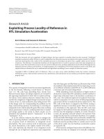
Figure 1: Dynamically reconfigurable system.
be made dynamically reconfigurable such that the context of
a hardware task can be saved and restored.
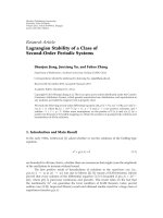
The dynamically reconfigurable system, as illustrated in
Figure 1, consists of a microprocessor attached to a system
bus with a communication memory, and a dynamically reconfigurable logic component such as FPGA, within which
hardware tasks can be configured and attached to a peripheral bus which in turn is connected through a bridge with
the system bus. Each hardware task consists of a hardware
IP, a wrapper, and a task interface. The hardware IP is an
application-specific function such as a DCT or an H.264
video decoder. In this work, two basic wrapper designs and
an enhanced wrapper design are proposed for dynamically
swappable design and the implementation of one of them
along with the standardizing hardware IP is used for demonstrating the practicality. The wrappers control the whole
swap-out and swap-in processes of the hardware task. The
task interface is an interface to a peripheral bus for data
transfers in a hardware task. The task interface acts as a bus
interface of the hardware task and is responsible for normal
data transfer operations through the control, read, and write
interfaces and for swapping and reconfiguration operations
through the swap interface.
In this work, our target system is based on the Xilinx Virtex II Pro FPGA chip, with the IBM CoreConnect on-chip
bus architecture. Swappable hardware tasks are attached to
the on-chip peripheral bus (OPB), while the microprocessor
and memory are attached to the processor local bus (PLB).
The FPGA chip consists of configurable logic blocks (CLB),
I/O blocks (IOB), embedded memory, routing resources, and
an internal configuration access port (ICAP). Reconfiguration
is achieved through the ICAP by configuring a bitstream.
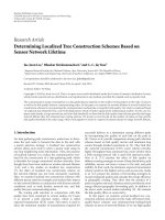
The software task management in an OS4RS is similar
to that in a conventional OS. The hardware task management is as shown in Figure 2, where the OS4RS uses a priority
scheduling and placement algorithm. Each hardware task has
a priority, arrival time, execution time, reconfiguration time,
deadline, and area in columns. The OS4RS schedules and
places the hardware tasks to be executed by swapping them
into the reconfigurable logic and it also preempts running
tasks by swapping them out and storing their contexts to the
external communication memory. Reconfigurable resources,
including CLB, IOBs, and routing resources, are managed
and reconfiguration is controlled by the OS4RS through the
ICAP.
4.
DYNAMICALLY SWAPPABLE DESIGN
Given the dynamically reconfigurable system architecture described in Section 3, we focus on how a digital hardware IP
can be automatically transformed into a dynamically swappable hardware task. For a nonswappable hardware IP, three
major modifications required to make it swappable include
the standardization of the hardware IP for interfacing with a
generic wrapper, the wrapper design itself for swapping the
hardware IP, and a task interface for interfacing with the peripheral bus.
4.1.
Standardizing hardware IP
Since a combinational circuit is stateless, it can be swapped
out from the reconfigurable logic as soon as it finishes the
current computation. However, a sequential circuit is controlled by a finite state machine (FSM) through the present
and next state registers. Generally, a hardware IP has one or
more data registers for storing intermediate results of computation. The collection of the state registers and data registers constitutes the task context. A state is said to be interruptible if the hardware task can resume execution from that state
after restoring the task context, either partially or fully. Not
all states of a hardware task are interruptible. For the FSM of
a GCD IP example given in Figure 3, only the INIT, RLD, and
4
EURASIP Journal on Embedded Systems
Place, swap-in,
execute task
the capability for dynamic swapping. Two basic wrapper designs and an enhanced wrapper design are introduced and
their interfacing is illustrated as follows.
Schedule HW
tasks
4.2.
Yes
logic resources
available
No
Is it a higher
priority task?
No
Yes
Send “swap-out” to
lower priority HW tasks
Wait for “swap-fin”
Yes
Sufficient logic
resources?
No
Figure 2: Hardware task scheduling and reconfiguration in an
OS4RS.
CMP states are interruptible because the comparator results
are not saved and hence we cannot resume from the NEG,
EQ, and POS states.
The initial or the idle state is always interruptible. Any
other state of a hardware IP can be made interruptible by
adding or reusing registers provided the computation can be
resumed after context restoring. However, extra resources are
required, thus the benefit obtained by making a state interruptible should be weighed against the overhead incurred in
terms of both logic resources and context saving and restoring time. In general, making a state interruptible allows the
hardware task to be switched at that state, and thus the delays in executing other hardware tasks are reduced. Hence,
making a state interruptible brings no benefit to the task itself, instead it may shorten the overall system schedule. The
decision to make a state interruptible must be derived from
an overall system analysis rather than from the perspective of
the hardware task itself.
A hardware IP is standardized automatically by making
the context registers accessible by the wrapper and by enhancing the FSM controller such that the IP can be stalled at
each interruptible state. This is done in the same way as design for test (DFT) techniques that perform scan-chain insertions after the design is completed. Tool support is planned
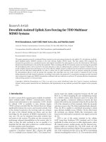
for the future. For the GCD IP, its standardized version that
is dynamically swappable is shown in Figure 3, where the two
registers are made accessible to the wrapper (swap circuitry)
and the FSM is modified such that the IP can be stalled in the
CMP state. Furthermore, a standardized hardware IP needs
to be combined with either one of the basic wrapper designs
[14] or an enhanced wrapper design for being enhanced with
Basic wrapper designs
Two basic wrapper architectures, namely last interruptible
state swap (LISS) wrapper and next interruptible state swap
(NISS) wrapper, are proposed for controlling the swapping
of a hardware circuit into and out from a reconfigurable
logic such that all swap circuitry is implemented within the
wrappers with minimal changes to the hardware IP itself.
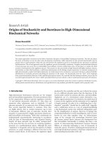
As shown in Figure 4, the wrapper architectures consist of
a context buffer (CB) to store context data, a data path for
data transfer, a swap controller (SC) to manage the swapout and swap-in activities, and some optional data transformation components (DTCs) for (un)packing data types. A
generic wrapper architecture interfaces with a hardware IP
and a standard task interface that connects with a peripheral
bus. The difference between the two wrappers lies in the
swap-out mechanism and the hardware state in which the
IP is swapped out. The LISS wrapper stores the IP context at
each interruptible state, thus the IP can be swapped out from
the last interruptible state whenever there is a swap request.
The NISS wrapper requires the IP to execute until the next
interruptible state, store the context, and then swap out. In
Figure 4, the LISS wrapper does not include the W interrupt
and swap fin signals, while the NISS wrapper does (signals
are highlighted using dotted arrows). The different swap-out
processes and the same swap-in process are described as follows.
4.2.1. LISS wrapper swap-out
At every interruptible state, the context of hardware IP
is stored in a context buffer using the Wout State and
Wout cdata signals. When there is a swap out request from
the OS4RS for some hardware task, the wrapper sends an Interrupt signal to the microprocessor to notify the OS4RS that
(1) the context data stored in the context buffer can be read
and saved into the communication memory, and (2) the resources can be deallocated and reused (reconfigured). The
swap-out process is thus completed. This wrapper can be
used for hardware circuits whose context data size is less than
that of the context buffer, as a result of which all context data
can be stored in the context buffer using a single data transfer.
4.2.2. NISS wrapper swap-out
When there is a swap out request from the OS4RS for some
hardware task, the swap controller in the wrapper sends a
swap signal (asserted high) to the hardware IP, which starts
the whole swap out process. However, the hardware IP might
be in an unswappable state, thus execution is allowed to
continue until the next swappable state is reached. At a
swappable state, the context of hardware IP, including current state information and selected register data, is stored
in a context buffer in the wrapper using the Wout State and
C.-H. Huang and P.-A. Hsiung
5
W Go
Win cdata X
YWDi
XWDi
W clk
W rst
Win cdata Y
GCD
swap
DataPath
Controller
Y sel
Idle
X sel
Y ld
INIT
RLD
Wout state
CMP
Win State
NEG
POS
EO
MUX for X
MUX for Y
X ld
W interrupt
Register
Register
Wout cdata X
rel handle
X gt Y
X lt Y
X eq Y
int handle
Store ok
Wout cdata Y
Comparator
Subtractor
enable
Out register
WDo
Figure 3: Swappable GCD circuit architecture.
Wout cdata signals. The hardware IP then sends an acknowledgment W interrupt to the wrapper that the swap-out process can continue. The wrapper sends an Interrupt signal
to the microprocessor to notify the OS4RS that the context
data stored in the context buffer can be read and saved into
the communication memory. This wrapper can be used when
the context data size is larger than that of the context buffer
by repeating the process of storing into buffer, interrupting
microprocessor, and reading into memory. Finally, when all
context data have been stored into the communication memory, the wrapper sends a swap fin signal to the task interface,
thus notifying the OS4RS that the resources occupied by the
IP can be deallocated and reused. The swap-out process is
thus completed.
4.2.3. Swap-in
When a hardware task is scheduled to be executed, the OS4RS
configures the corresponding hardware IP with wrapper and
task interface into the reconfigurable logic using the internal configuration access port (ICAP), reloads the context
data from the communication memory to the context buffer
in the wrapper, and sends a swap in request to the swap
controller, which then starts to copy the context data from
the buffer to the corresponding registers in the IP using
Win State and Win cdata. After all context data are restored,
the swap controller sends a swap signal (asserted low) to the
hardware IP, which then continues from the state in which it
was swapped out.
It must be noted here that context data might be of
different sizes for different hardware IPs, so data packing
and unpacking are performed using the data transformation component (DTC) within the wrapper. For the standardized GCD IP example given in Figure 3, there are two
8-bit X Wout cdata and Y Wout cdata signals from the IP,
which are packed by the DTC in the wrapper into a 32-bit
Out context signal for storing into communication memory
through the peripheral bus. The other signals in Figure 4 are
used for normal IP execution.
4.3.
Task interface
The task interface, as illustrated in Figure 4, acts as a bus interface of the hardware task. A task interface consists of a read
interface and a write interface to control read and write operations, respectively, a control interface to manage IP-related
control signals, a swap interface to manage the swapping process and reconfiguration of the hardware design, a bus control interface to deal with the interactions between the bus
and above interfaces. The task interface presently supports
the CoreConnect OPB only. The PowerPC 405 and communication memory are bound on the CoreConnect PLB bus,
where the PowerPC 405 can interact with the hardware tasks
on the OPB bus by utilizing the PLB-OPB bridge as shown
in Figure 1. The PLB-OPB bridge is the OPB master and it
is responsible for communicating the signals from the PowerPC 405 to the hardware tasks, while the swappable hardware tasks along with wrappers are the OPB slaves. In the future, we will design different task interfaces for other peripheral buses such as AMBA APB. By changing the task interface, a swappable hardware IP can be connected to different
peripheral buses.
4.4.
Enhanced wrapper design along with OPB IPIF
In this section, an enhanced LISS wrapper along with OPB
intellectual property interface (IPIF) architecture is proposed,
where the OPB IPIF architecture provides additional optional services to standardize functionality that is common to
many hardware IPs and to reduce hardware IP development
effort. As shown in Figure 5, a swappable hardware design
6
EURASIP Journal on Embedded Systems
Control interface Write interface Read interface
Bus control interface
Peripheral bus
Task interface
Wrapper
Out context
Context
buffer
DTC
In context
Wout cdata
Do
WDi
DataPath
Di
WDo
clk
W clk
rst
HW
IP
W rst
W Go
Go i
swap out
swap interface
Win State
Wout State
Win cdata
swap
controller
swap
swap in
wap fin
Interrupt
W interrupt
Interrupt
controller
Figure 4: Wrapper architecture and interfaces.
along with the enhanced LISS wrapper is specified as an OPB
IPIF slave, where the OPB IPIF architecture consists of a reset
component to reset a hardware IP, an Addr decode to decode
the OPB address, a slave interface to provide software accessible registers, a Write FIFO and a Read FIFO for write and read
data transfers, respectively, and an IP interconnect (IPIC) for
connecting the user logic to the IPIF services.
For this enhanced LISS wrapper design, the basic data
transfers are directly accessed by the slave interface instead
of the datapath in the LISS wrapper, while the context data
is stored in the Write FIFO and Read FIFO in place of the
context buffer in the LISS wrapper. The DTC component in
the wrapper is responsible for (un)packing data type, where
the signals In context and Out context are used for transferring context data packages from Write FIFO or to Read
FIFO. By using the Xilinx EDK tool [15], the size of Write
FIFO and Read FIFO can be adjusted to fit that of the context data, which makes context data transfers to be not only
unrestricted by the context buffer size, but also to provide
the capability of dealing with larger context data size similar to the NISS wrapper. Furthermore, when using the Xilinx
EDK tool, the number of software accessible registers is decided according to the swap-out and swap-in activities, the
data transfers of a hardware IP, and all required control signals.
The swap-in and swap-out processes of the enhanced
LISS wrapper are similar to those of the LISS wrapper in addition to the signal swap fin for notifying the OS4RS to read
the context data in the Read FIFO, instead of the signal Interrupt in the LISS wrapper. In order to demonstrate the feasibility of our swappable hardware design, a swappable IP with
our enhanced LISS wrapper design, which is implemented
on the Xilinx ML310 embedded development platform [16],
will be introduced in Section 5.
5.
CASE STUDY: A SWAPPABLE DCT HARDWARE TASK
As shown in Figure 6, a design flow for dynamically swappable hardware design is proposed, and a discrete cosine
transform (DCT) IP with our enhanced LISS wrapper design,
which is implemented on the Xilinx ML310 embedded development platform, is used for illustrating how to make an
unswappable DCT IP swappable.
A DCT IP transforms an image having 128 blocks of
size 8 × 8 pixels, in which a block is read and saved at a
time into an 8 × 8 array, called Block i. Another 8 × 8 array, called Block o, is used for saving the results, where each
result is produced in turn using all data of Block i. After analyzing the DCT design, the context data, including all data
of Block i and the row and column indices of the present
C.-H. Huang and P.-A. Hsiung
7
IPIF IP core
Wrapper
Write FIFO
Win State
In context
Wout State
Out context
DTC
Win cdata
Read FIFO
OPB bus
Wout cdata
Reset
Slave
attachment
IPIC
and
“glue”
HW
IP
Addr
decode
swap out
swap
controller
swap
swap in
Slave
I/F
swap fin
Figure 5: Enhanced LISS wrapper architecture.
iteration, are recorded. The DCT IP needs to be standardized
for accessing the context data as shown in Figure 7, and combined with our enhanced LISS wrapper, as shown in Figure 5,
by connecting with the Win State, Wout State, Win cadta,
Wout cdata, and swap signals. By using Xilinx EDK tool, a
swappable DCT hardware task, including a swappable DCT
IP and our enhanced LISS wrapper, is designed as a slave
attached to the OPB bus, where the size of FIFOs and the
number of software accessible registers are decided according to the analysis results of context data.
The design flow for swappable hardware design is illustrated in Figure 6 and designed on follows. Owing to the
Xilinx EDK tool being suitable only for full chip design,
the netlist of the swappable DCT IP with the wrapper is
extracted. Furthermore, the HDL of top module is modified for fitting the constraint on partial reconfiguration design flow and bus macros are added to reconnect a swappable DCT hardware task with the OPB bus. Finally, the
netlist of the new top module is regenerated. After following the above process and then using the partial reconfiguration design flow [17], the full bitstream and the partial
bitstream of swappable DCT task are generated. The design flow for dynamically swappable hardware design is thus
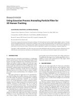
completed. The complete result of a dynamically swappable
DCT hardware task in a partially reconfigurable system is
shown in Figure 8, where the dynamic module of the swappable DCT hardware task, and the static module including
two PowerPC405 microprocessors, an ICAP, a PLB bus, and
an OPB bus, and the bus macros for connecting the dynamic module with the static module, are highlighted for
displaying the relative location of each component in the
FPGA.
6.
EXPERIMENTS
In order to demonstrate the feasibility of our proposed swappable hardware design, six different hardware IPs are used
for analyzing the overhead of IP standardization and comparing the time for context switching with that required by
reconfiguration-based method.
6.1.
Resource overhead analysis
We performed all our experiments on the Xilinx Virtex II Pro
XC2VP20-FF896 FPGA chip that is organized as a CLB matrix of 56 rows and 46 columns, including 18,560 LUTs and
18,560 flip-flops. All swappable hardware tasks are connected
to a 32-bit CoreConnect OPB bus operating at 133 MHz.
For the experiments, we synthesized and simulated the swappable versions of the hardware IPs. The OS4RS running on
the PowerPC was based on an in-house extension of the
Linux OS. There was no specific application running to avoid
inaccuracies in experimental results.
We standardized six different hardware IPs, as described
in Section 4.1, implemented the generic wrappers, as discussed in Sections 4.2 and 4.4. We used the Synplify synthesis
tool and the ModelSim simulator to verify the correctness of
the wrapper and the modified hardware IP designs. We compared the original hardware IP designs with the new swappable ones for each example.
8
EURASIP Journal on Embedded Systems
HW IP
Analysis results
of context data
Standardize
Swappable HW IP
Combine with wrapper
Attach swappable HW IPs
with wrapper to OPB bus
Select the size of FIFOs and the By EDK
number of SW accessible registers
Generate netlist
Modify the HDL of top
module for PR flow
Extract the netlist of
swappable HW IPs
Add bus macro to
re-connect swappable HW
IPs with OPB bus
Re-generate netlist
for top module
Full bitstream
Follow PR flow
Partial bitstream
(swappable HW IPs)
Figure 6: Design flow for swappable hardware designs.
The examples included two GCDs as shown in Figure 3,
a traffic light controller (TLC), a multiple lights controller
(MLC), and a data encryption standard (DES) design, and a
DCT as shown in Figure 7. The GCD can be swapped out in
the middle of calculating the greatest common divisor of two
8-bit or 32-bit integers and swapped in to continue the computation. The computation results were verified correct for
all test cases. The TLC drives the red light for 9 clock cycles,
the yellow light for 2 clock cycles, and the green light for 6
clock cycles. The TLC can be swapped out and continue from
where it left. The MLC is an extension of the TLC with more
complex light switching schemes. The DES is a more complex design that can effectively demonstrate the practicality
of the proposed swappable design. The DCT design transforms an image having 128 blocks of size 8 × 8 pixels. All the
IPs were made swappable, interfaced with the wrapper and
the swapping was verified correct in the sense that they finished their computations correct irrespective of when they
were interrupted.
The resource overhead required for making a hardware
IP swappable includes the extra resources required to make
the context registers and the current state register visible.
Our synthesis results and comparisons are given in Table 1,
where making a hardware IP to interact with the enhanced
LISS wrapper and that with the LISS wrapper are the same
so that the first three examples include only two cases. We
can observe that the overheads in making the IPs swappable
seem to be around 60% for the simple 8-bit GCD and the
TLC examples, while for the more complex 32-bit GCD and
MLC examples the overhead is only 22%∼33%, which shows
that the overhead in resources depends only on the amount
of context data to be saved and restored and the number of
interruptible states, and does not depend on the complexity of the full hardware design. The original DES design is
synthesized into thirty-two 64 × 1 ROMs. Making the DES
design swappable, it needs an extra 51% or 47% flip-flops
but only 2% LUTs, in terms of the available FPGA resources,
the overhead is quite small. The swappable DCT needs 33%
more flip-flops, but −13% or −14% less LUTs due to synthesis compiler optimization. One can observe that flip-flop
overheads are high, but the LUTs overheads are low. The increase in flip-flop is mainly due to the need for extra I/O
registers for storing context data. However, since there are
usually a large number of unused flip-flops in the CLBs of
a synthesized circuit, the design after placement and routing will not result in a significant increase in the CLB count.
The reduction in LUTs after standardization of the DCT circuit is due to all context registers being made accessible in
C.-H. Huang and P.-A. Hsiung
9
Win cdata block
swap
in data out data
Wout cdata block
rd wr addr
DCT
FSM 1
Idle
Idle
Wait
Increment
Done
Go
Row/col register
Wout State row
Read/write controller
FSM 2
Transform
Compute
Finish
COS TABLE
Block i
Transform
Convert
Block o
Win State col
Wout State col
Win State col
Figure 7: Swappable DCT circuit architecture.
Table 1: Synthesis results and resource overheads.
HW
V
PPC405
Swappable
DCT
PLB
OPB
Bus
macro
ICAP
Figure 8: Swappable DCT design along with enhanced LISS wrapper.
parallel, which results in the elimination of multipliers and
multiplexers and thus fewer LUTs in the swappable circuit.
The complex DCT design more explicitly shows the feasibility of our proposed swappable design. For task G8 , the FF
and LUT overheads are 54% and 42% for LISS, and 70% and
52% for NISS, respectively. We can observe that the overheads in making the IPs swappable for interfacing with the
LISS wrapper are smaller than that for interfacing with the
NISS wrapper. This is due to the lesser number of signals in
LISS wrapper and the more complex circuitry in NISS wrapper for transferring context data of sizes greater than that of
context buffer. The implementation results obviously show
that the extra FPGA resources required for making a hardware IP swappable are only dependent on the amount of
context data and the number of interruptible states, where
N
TLC
L/E
N
MLC
L/E
N
G8
L/E
N
G32
E
N
DES
E
N
DCT
E
DC
(bits)
IP
3
6
3
13
19
31
67
103
836
137
1030
1573
FF
SIP
10
10
17
17
53
48
169
168
207
202
2094
2103
+%
66
66
30
30
70
54
64
63
51
47
33
33
IP
24
63
80
270
589
1339
LUT
SIP
43
39
77
77
122
114
360
365
603
603
1152
1140
+%
79
62
22
22
52
42
33
35
2
2
−13
−14
V: version, DC : context data size, G8 : 8-bit GCD, G32 : 32-bit GCD, L: LISS
wrapper, N: NISS wrapper, E: enhanced LISS wrapper, IP: IP resource usage, SIP: swappable IP resource usage, +%: % of overheads in SIP compared
to IP.
the amount of resource overhead compared to the original
hardware IP are getting lesser and lesser for more and more
complex hardware designs, and when compared to the total
available FPGA resource the overheads are negligible.
6.2.
Efficiency analysis
We now analyze the performance of the proposed wrappers. Given context data of DC -bits, context buffer of DB bits, each FIFO entry of DF -bits, data transformation rate
of RT bits/cycle, buffer data load rate of RB bits/cycle, FIFO
entry load rate of RF bits/cycle, peripheral bus data transfer
rate of RP bits/cycle, peripheral bus access time of TA cycles,
10
EURASIP Journal on Embedded Systems
Table 2: Time overheads for swap-out and swap-in.
TE
V
TLC
MLC
G8
G32
DES
DCT
N
L
E
N
L
E
N
L
E
N
E
N
E
N
E
17
33
511
1671
1,424
71,552
TB
3
2
2
3
2
2
4
2
2
11
9
84
58
100
68
swap-out
TP
TSO (ns)
3
64
3
39
3
39
3
64
3
50
3
50
3
46
3
38
3
38
9
157
9
140
81
962
81
917
99
1,600
99
1,292
TB
2
2
2
2
2
2
2
2
2
5
3
55
29
66
34
swap-in
TP
TSI (ns)
3
50
3
39
3
39
3
50
3
50
3
50
3
38
3
38
3
38
9
108
9
92
81
840
81
763
99
1,309
99
1,018
TR
(ns)
46,336
42,025
83,243
83,243
131,465
122,844
387,931
401,589
649,784
649,784
1,267,481
1,254,278
TSO
(µs)
46.4
46.4
46.4
83.3
83.3
83.3
131.5
131.5
131.5
388.0
401.7
650.7
650.7
1269.0
1255.5
TSI
(µs)
46.3
46.3
46.3
83.2
83.2
83.2
131.5
131.5
131.5
388.0
401.6
650.6
650.6
1268.7
1255.2
Task relocate
Our (µs)
RMB (µs)
92.7
496.7
92.7
92.7
166.5
582.5
166.5
166.5
263.0
619.9
263.0
263.0
776.0
1038.1
803.3
1301.3
2183.8
1301.3
2537.8
4278.2
2510.7
RBM: Reconfiguration-based method, TE : execution time (in IP clock cycles), TB = (DB /RT ) + (DB /RB ) or TB = (DF /RT ) + (DF /RF ) (in IP clock cycles),
TP = TA + (DB /RP ) or TP = TA + (DF /RP ) (in bus cycles), TSO = TSO − TR (in nanoseconds), TSI = TSI − TR (in nanoseconds).
transition time of TI cycles to go to an interruptible state
(TI is 0 for LISS), and reconfiguration time of TR cycles, the
swap-out and swap-in processes require time TSO and TSI , respectively, for both the NISS and the LISS wrappers as shown
in (1), while that for the enhanced LISS wrapper is as shown
in (2):
TSO = TI +
DC
DB DB
D
+
+ TA + B + TR ,
×
DB
RT RB
RP
DC
DB DB
D
TSI = TR +
+
+ TA + B .
×
DB
RT RB
RP
(1)
Both swap times are dominated by the reconfiguration
time TR . For Xilinx XC2VP20-FF896 FPGA chip, the reconfiguration clock runs at 50 MHz such that a byte can be
configured in 20 nanoseconds, however a full bitstream is
1,026,820 bytes, which means a full chip configuration requires around 20 milliseconds. However, all other times in
(1) and (2) are only a few cycles, in the nanoseconds order
of magnitude. The wrapper overhead as shown in the experiments accounts for at most 2 cycles assuming that the
context buffer can be loaded in 1 cycle. Our design-based
dynamic reconfiguration approach is very data-efficient because the readback time required by reconfiguration-based
methods [3, 4] is also in the same order of magnitude as the
reconfiguration time TR :
TSO =
DC
DF DF
D
+
+ TA + F
×
DF
RT RF
RP
+ TR ,
DC
DF DF
D
+
+ TA + F .
TSI = TR +
×
DF
RT RF
RP
(2)
As shown in Table 2, the time overheads in swapping out
and swapping in for all the examples consume only a few cycles and are in the order of nanoseconds. From Table 2, we
can observe that not only is swapping faster with the LISS
wrapper or the enhanced LISS wrapper, but their simpler
circuities also require lesser reconfiguration time TR , compared to NISS. However, as mentioned before, LISS wrappers can only be used when the IP context size is not greater
than that of the context buffer size, but the enhanced LISS
wrapper can be unrestricted to the context buffer size and
efficient than the NISS wrapper when the IP context size is
greater than that of the context buffer size. We can thus conclude that the enhanced LISS wrapper is suitable for dynamically swappable hardware design irrespective of the context
data size. It is assumed here that TI = 0 because the time
to transit to a swappable state is not a fixed one and depends on when the OS4RS sends in the swap signals. We
assume typical OPB read and write data transfers for swapout and swap-in, respectively; hence, each of them needs 3
bus cycles for a single 32-bit data transfer. Comparing the
time required for a task relocation, that is, one swap-out and
one swap-in, our proposed design-based method performs
better than the reconfiguration-based methods (RBM) [3].
From the experimental results, RBM methods not only require a reconfiguration time of 648 microseconds for DES
and 1473.2 µs for DCT, but they also require a readback
time of 887.8 µs for DES and 1331.8 microseconds for DCT,
while we reduce 40.4% and 40.6% for the NISS wrapper, and
40.4% and 41.3% for the enhanced LISS wrapper, respectively, of the time required by reconfiguration-based methods, respectively, for the larger DES and DCT examples. We
are thus saving much time, which is important for hard realtime systems. Even though additional reconfiguration time
C.-H. Huang and P.-A. Hsiung
is required, the swappable design would enable more hardware tasks to fit their deadline constraints, which makes the
hardware-software scheduling in an OS4RS more flexible for
achieving higher system performance.
7.
CONCLUSIONS
We have proposed a method for the automatic modification
and enhancement of a hardware IP such that it becomes dynamically swappable under the control of an operating system for reconfigurable systems. We have designed two basic
wrapper designs and an enhanced LISS wrapper design, and
analyzed the conditions for using the wrappers. We have also
proposed how the hardware IP can be minimally changed
by only making the state and context registers visible. The
proposed method and architectures were implemented and
verified. Our experiment results show that the resource and
time overheads of making an IP swappable are quite small
compared to the amount of reconfigurable resources available and the configuration time of the IP, respectively.
REFERENCES
[1] Xilinx. XAPP290—two flows for partial reconfiguration module-based or difference-based, 2004.
[2] R. Gamma, R. Helm, R. Johnson, and J. Vissides, Design Patterns: Elements of Reusable Object-Oriented Software,
Addison-Wesley Professional Computing Series, AddisonWesley, Reading, Mass, USA, 1994.
[3] H. Kalte and M. Porrmann, “Context saving and restoring for
multitasking in reconfigurable systems,” in Proceedings of International Conference on Field Programmable Logic and Applications (FPL ’05), vol. 2005, pp. 223–228, Tampere, Finland,
August 2005.
[4] H. Simmler, L. Levinson, and R. Mă nner, Multitasking on
a
FPGA coprocessors, in Proceedings of the 10th International
Conference on Field-Programmable Logic and Applications (FPL
’00), pp. 121–130, Villach, Austria, August 2000.
[5] M. Ullmann, B. Grimm, M. Hă bner, and J. Becker, “An FPGA
u
run-time system for dynamical on-demand reconfiguration,”
in Proceedings of the 11th Reconfigurable Architectures Workshop (RAW ’04), Santa Fe, NM, USA, April 2004.
[6] J.-Y. Mignolet, V. Nollet, P. Coene, D. Verkest, S. Vernalde,
and R. Lauwereins, “Infrastructure for design and management of relocatable tasks in a heterogeneous reconfigurable
system-on-chip,” in Proceedings of the Design Automation and
Test in Europe (DATE ’03), vol. 1, pp. 986–991, Munich, Germany, March 2003.
[7] G. Brebner, “The swappable logic unit: a paradigm for virtual
hardware,” in Proceedings of the 5th Annual IEEE Symposium
on FPGAs for Custom Computing Machines (FPGA ’97), pp.
77–86, Napa Valley, Calif, USA, April 1997.
[8] J. Noguera and R. M. Badia, “Multitasking on reconfigurable architectures: microarchitecture support and dynamic
scheduling,” ACM Transactions on Embedded Computing Systems, vol. 3, no. 2, pp. 385–406, 2004.
[9] D. Kearney and R. Kiefer, “Hardware context switching in a
signal processing application for an FPGA custom computer,”
in Proceedings of the 4th Australasian Computer Architecture
Conference (ACAC ’99), pp. 35–46, Auckland, New Zealand,
January 1999.
11
[10] H.-Y. Sun, “Dynamic hardware-software task switching and
relocation for reconfigurable systems,” M.S. thesis, Department of Computer Science and Information Engineering, National Chung Cheng University, Chiayi, Taiwan, 2007.
[11] P.-A. Hsiung, C.-H. Huang, and Y.-H. Chen, “Hardware task
scheduling and placement in operating systems for dynamically reconfigurable SoC,” to appear in Journal of Embedded
Computing.
[12] V. Nollet, P. Coene, D. Verkest, S. Vernalde, and R. Lauwereins,
“Designing an operating system for a heterogeneous reconfigurable SoC,” in Proceedings of the 17th International Symposium on Parallel and Distributed Processing (IPDPS ’03), p. 174,
Nice, France, April 2003.
[13] C. Steiger, H. Walder, and M. Platzner, “Operating systems for
reconfigurable embedded platforms: online scheduling of realtime tasks,” IEEE Transactions on Computers, vol. 53, no. 11,
pp. 1393–1407, 2004.
[14] C.-H. Huang, K.-J. Shih, C.-S. Lin, S.-S. Chang, and P.-A. Hsiungt, “Dynamically swappable hardware design in partially
reconfigurable systems,” in Proceedings of IEEE International
Symposium on Circuits and Systems (ISCAS ’07), pp. 2742–
2745, New Orleans, La, USA, May 2007.
[15] Xilinx. Embedded system tools reference manual—embedded
development kit EDK 8.1i, 2005.
[16] Xilinx. ML310 User Guide, 2007.
[17] Xilinx. UG208—Early Access Partial Reconfiguration User
Guide, 2006.