Báo cáo hóa học: " Joint Frequency Ambiguity Resolution and Accurate Timing Estimation in OFDM Systems with Multipath Fading" doc
Bạn đang xem bản rút gọn của tài liệu. Xem và tải ngay bản đầy đủ của tài liệu tại đây (673.98 KB, 7 trang )
Hindawi Publishing Corporation
EURASIP Journal on Wireless Communications and Networking
Volume 2006, Article ID 62173, Pages 1–7
DOI 10.1155/WCN/2006/62173
Joint Frequenc y Ambiguity Resolution and Accurate Timing
Estimation in OFDM Systems with Multipath Fading
Jun Li,
1
Guisheng Liao,
1
andShanOuyang
2
1
National Laboratory of Radar Signal Processing, Xidian University, Xi’an 710071, China
2
Department of Communication and Information Engineering, Guilin University of Electronic Technology, Guilin 541004, China
Received 29 May 2005; Revised 28 September 2005; Accepted 4 November 2005
Recommended for Publication by Lawrence Yeung
A serious disadvantage of orthogonal frequency-division multiplexing (OFDM) is its sensitivity to carrier frequency offset (CFO)
and timing offset (TO). For many low-complexity algorithms, the estimation ambiguity exists when the CFO is greater than one
or two subcarrier spacing, and the estimated TO is also prone to exceeding the ISI-free interval within the cyclic prefix (CP).
This paper presents a method for joint CFO ambiguity resolution and accurate TO estimation in multipath fading. Maximum-
likelihood (ML) principle is employed and only one pilot symbol is needed. Frequency ambiguity is resolved and accurate TO
can be obtained simultaneously by using the fast Fourier transform (FFT) and one-dimensional (1D) search. Both known and
unknown channel order cases are considered. Computer simulations show that the proposed algorithm outperforms some others
in the multipath fading channels.
Copyright © 2006 Jun Li et al. This is an open access article distributed under the Creative Commons Attribution License, which
permits unrestricted use, distribution, and reproduction in any medium, provided the original work i s properly cited.
1. INTRODUCTION
Orthogonal frequency-division multiplexing (OFDM) is an
effective technique to deal with the multipath fading channel
in high-rate wireless communications [1]. It has been chosen
for the European digital audio and video broadcasting stan-
dards, as well as for the wireless local-area networking stan-
dards IEEE802.11a and HIPERLAN/2. It is also a promising
candidate for the fourth-generation (4G) mobile communi-
cation standard.
Despite many advantages, OFDM systems are very sen-
sitive to symbol timing offset (TO) and carrier frequency
offset (CFO) [2, 3]. A lot of schemes for CFO and TO es-
timation for OFDM systems have been proposed in the lit-
erature [4–12]. However, most low-complexity estimation
approaches can only estimate the CFO within one or two
subcarrier spacing [4–6]. When the CFO is larger than one
subcarrier spacing, the frequency ambiguity would appear.
The frequency ambiguity is called integer frequency offset
(IFO) because it is the integer multiple of one subcarrier
spacing. The part of CFO within one subcarrier spacing is
called fractional frequency offset (FFO). Schmidl and Cox
[7] presented an efficient algorithm (called SCA for simplic-
ity) for estimating the FFO, IFO, and TO. For the IFO es-
timation, however, their algorithm requires the observation
of two consecutive symbols and supposes that the symbol
timing is perfect. Moreover, the broad timing metric plateau
inherent in [7] results in a large TO estimation variance.
Morelli et al. [8]andChenandLi[9] enhanced the per-
formance of SCA [7] for the IFO estimation by employ-
ing maximum-likelihood (ML) technique (note that if there
is no virtual subcar rier, Morelli’s method is equivalent to
Chen’s method). However, their methods require perfect
timing still. Park et al. [10] proposed an IFO estimator robust
to the timing error, but its performance is unsatisfactory (see
Figure 3).
In this paper, an efficient method for joint estimation
of the IFO and TO in multipath fading channels is derived.
Maximum-likelihood principle is employed and only one
pilot symbol is needed. Both of them can be obtained by
using the fast Fourier transform (FFT) and one-dimensional
(1D) search. The estimation in the cases of known channel
order (KCO) and unknown channel order (UCO) are also
discussed. Our method for IFO estimation outperforms
the methods in [7–10], even if those methods use two pilot
symbols. The perfor m ance of the proposed method for
TO estimation is also better than that of the conventional
methods [7, 11] in multipath fading channel. In effect, our
approach can be viewed as an extension of the Morelli and
Mengali algorithm [ 13].
2 EURASIP Journal on Wireless Communications and Networking
Channel impulse
response
N + L
CP
(pilot symbol including CP)
L
CP
(CP)
τ
τ
0
L
Reference point of
the timing (0)
ISI-free
Observation
windows N
Figure 1: Accurate timing position under multipath fading.
The organization of this paper is as follows. The signal
model of OFDM is introduced in Section 2.InSection 3 , the
algorithm for joint timing and IFO estimation using FFT
is developed and the estimation in the cases of UCO and
KCO are discussed. Computer simulations are presented in
Section 4 to demonstrate the performance of the proposed
algorithm with comparisons to the available methods [7, 9–
11]. Section 5 concludes the paper.
Notation
Capital (small) bold face l etters denote matrices (column
vectors). Frequency domain components are indicated by a
tilde. (
·)
∗
,(·)
T
,and(·)
H
represent conjugate, transpose, and
conjugate transpose, respec tively.
·denotes the Frobenius
norm, and I
N×N
denotes the N × N identity matrix. Re(·)
denotes the real part of a complex number (
·). diag(·)de-
notes a diagonal matrix constructed by a vector.
∗ denotes
the convolution and fft(
·) denotes the FFT of the columns of
amatrix.
2. PROBLEM FORMULATION
The OFDM signal is generated by taking the N-point inverse
fast Fourier transform (IFFT) of a block of symbols with a
linear modulation such as PSK and QAM. The OFDM sam-
ples at the output of IFFT are given by
x( i)
=
N−1
n=0
a
n
exp( j2πni/N)
√
N
,0
≤ i ≤ N − 1, (1)
where
a
n
is modulated data sequence with unit energy. The
useful part of each block has the duration of T seconds and
is preceded by a cyclic prefix (CP) with the size of L
CP
,longer
than the channel impulse response, so as to eliminate the in-
terference between adjacent blocks. Each OFDM block is se-
rialized for the transmission through the possible unknown
time-invariant composition multipath channel. The channel
can be denoted by a discrete-time filter h(l)withorderL
(L
≤ L
CP
):
h(l)
= g
tr
(t) ∗ h
p
(t) ∗ g
rec
(t)|
t=lT
s
−t
0
,(2)
where g
tr
(t)andg
rec
(t) are, respectively, the response of
transmitting and receiving filters. h
p
(t) is the impulse
response of the dispersive channel. T
s
= T/N is sampling
period, and t
0
is propagation delay. In the presence of a fre-
quency offset f , the samples at the receiving filter output are
r(k)
= exp
j2πk
v
I
+ v
F
N
L−1
l=0
h(l)x(k − l)+w(k), (3)
where v
I
and v
F
are, respectively, the IFO and the FFO nor-
malized by the subcarrier space 1/T, x(m(N + L
CP
)+n)is
the serialized version of the mth OFDM block with the nth
entry, and w(k) denotes zero-mean additive white Gaussian
noise (AWGN).
Assuming that a length-N observation window slides
through the received data stream (Figure 1), we can ob-
tain observation vectors represented by the following matrix
form:
r(τ)
= C
v
F
C
v
I
X(τ)hξ + w(τ), (4)
where τ is the start point of observation window, ξ
=
exp[ j2πτ(v
F
+ v
I
)/N],
r(τ)
=
r(τ), r(τ +1), , r(τ + N −1)
T
,
C(v)
= diag
1, exp
j2πv
N
, ,exp
j2πv(N − 1)
N
,
X(τ)
i, j
= x(i − j), τ ≤ i ≤ N + τ − 1, 0 ≤ j ≤ L − 1,
h
=
h(0), h(1), , h(L − 1)
T
,
(5)
and w(τ)
= [w(τ), , w(τ + N − 1)]
T
is a zero-mean Gaus-
sian vector with covariance matrix
C
w
= E
ww
H
=
σ
2
I
N×N
. (6)
As illustrated in Figure 1, as long as the timing estimate is
within the ISI-free guard interval, the timing offset, regard-
less of its values, will not degrade the system performance.
Assume the FFO is corrected in advance, then the term
C(v
F
)in(4) can be removed. We construct the matrix X
by pilot symbol [x
N−L+1
, , x
N
, x
0
, , x
N−1
] and replace the
matrix X(τ)in(4) by the matrix X.Thetermξ in (4)canbe
incorporated into the channel parameters h. Then the ob-
served data can be expressed as
r(τ) = C
v
I
Xh + w(τ). (7)
JunLietal. 3
Now, we can find from the first term in the right-hand
side of (7) that there are three kinds of unknown parame-
ters in (7), namely TO τ,IFOv
I
, and channel parameters.
Assume τ
0
is the offset from a given reference to the ISI-free
interval. Our task is to find τ
0
and estimate the IFO v
I
simul-
taneously based on the observation r(τ)forgivenX.
3. MAXIMUM-LIKELIHOOD ESTIMATION USING
FAST FOURIER TRANSFORM
In this section, the ML principle is applied to derive an al-
gorithm for jointly estimating the timing and IFO. The joint
estimation problem in the case of unknown channel order is
also discussed.
3.1. Derivation of the algorithm
Since all the parameters except for noise in (7) are determin-
istic, the log-likelihood function of received data can be rep-
resented as
ln(L)
= const −2N ln
σ
2
−
r(τ) −C
v
I
Xh
2
σ
2
. (8)
The estimation of τ, v
I
,andh is the solution of the fol-
lowing joint optimization problem:
h, τ, v
I
= min
ˆ
h,
ˆ
τ,
ˆ
v
I
r(τ) −C
v
I
Xh
2
. (9)
For given τ and v
I
, the minimum for (9)is
h =
X
H
X
−1
X
H
C
H
v
I
r(τ). (10)
Substituting (10) into (9), τ and v
I
can be obtained by
maximizing the following cost function:
J
v
I
, τ
=
C
H
v
I
r(τ)
H
P
C
H
v
I
r(τ)
(11)
=−b(0, τ)+2Re
N−1
m=0
b(m, τ)exp
−
j2πmv
I
N
,
(12)
b(m, τ)
=
N−1
k=m
[P]
k−m,k
r
∗
(k − m + τ)r(k + τ), (13)
where P
= X(X
H
X)
−1
X
H
and [P]
i, j
is the (i, j)th entry of P.
The main steps in obtaining (12) are outlined in the ap-
pendix.
As v
I
and τ are integers, the estimation range of the nor-
malized IFO v
I
is in [0, N −1] and the search range of timing
τ is in [0, L
τ
− 1] (assume τ
0
is in [0, L
τ
− 1]), where 0 is the
reference point of TO and L
τ
is the length of TO search.
Construct two N
× L
τ
matrices B and J whose entries
are denoted by b(m, τ)andJ(v
I
, τ), respectively. The cost
function (12) can be expressed in the following matrix form:
J
= 2Re
fft(B)
− B
0
, (14)
where B
0
is an N × N matrix with the same columns from
the first column of B.
The maximum entry of the matrix J can be obtained by
1D search. It is clear that the indexes of the row and col-
umn corresponding to the maximum entry of J represent the
IFO v
I
and the TO τ
0
,respectively.
3.2. Unknown channel order case
In fact, there is still a hidden parameter unknown in the data
model (7). In order to construct the matrix X, the channel
order L should be known in advance. Thus the additional
algorithm for the channel order estimation is needed. Fur-
thermore, since the channel order is varying in practice, the
matrices X and P have to be reconstructed according to dif-
ferent L. However, we find that the estimator is robust to the
overestimated channel order. Hence the channel order L can
be simply replaced by L
CP
under the condition of L
CP
≥ L
which is generally satisfied in OFDM systems. Therefore, we
do not need to estimate L and to reconstruct X and P.Com-
parisons of the KCO with the UCO will be given in detail
next.
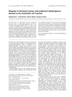
3.3. Effects of unknown channel order
Assume the IFO v
I
= 13 and the search range of TO is from
0–18. The cost function J(v
I
, τ) in the cases of the KCO and
UCO are plotted in Figure 2. It can be seen that the cost
function has a narrow timing metric plateau when v
I
= 13
in the case of KCO, whereas i t gives a wide timing metric
plateau within the ISI-free guard inter val in the case of UCO.
It should be noted that the wide plateau is likely to be be-
yond the ISI-free interval to degrade the performance (see
Simulation 2 in Section 4). For both the KCO and UCO, the
cost functions have the unique tall peak at the IFO metric.
However, the IFO metric of the UCO case has higher side-
lobes relative to the mainlobe than that of the KCO case. It
implies that there is still loss in terms of the performance
of the IFO estimation when channel order is unknown (see
Simulation 1 in Section 4).
Remarks
(1) Matrix P can be calculated in advance, which reduces
largely the burden of online computations.
(2) The multipath fading channel parameters can be ob-
tained by (10) after both the IFO and TO, are corrected. The
phase offset of estimated channel parameters can be compen-
sated by itself in the process of channel equalization.
(3) Only one pilot symbol is needed in the algorithm to
estimate the IFO, TO, and channel parameters, and the pilot
symbol can be selected as a random sequence.
(4) The proposed algorithm can also be extended to
MIMO-OFDM systems directly, if there are a set of pilot
symbols, each corresponding to a transmitting antenna.
4 EURASIP Journal on Wireless Communications and Networking
15
14
13
12
11
10
0
10
20
0
20
40
60
80
Cost J
IFO
TO (sample)
ISI-free
CP
(a)
15
14
13
12
11
10
0
5
10
15
20
0
20
40
60
80
Cost J
IFO
TO (sample)
ISI-free
CP
(b)
Figure 2: Cost function for joint IFO and TO estimations (N = 64, L
CP
= 16, L = 8, SNR = 20 dB, v
I
= 13): (a) the case of KCO and (b)
thecaseofUCO.
4. SIMULATION RESULTS AND DISCUSSIONS
The performance of the proposed approach to joint estima-
tion of the IFO and TO is evaluated by computer simula-
tions. Consider an OFDM system with 64 subcarriers and
the length of cyclic prefix with 16 samples. The QPSK sym-
bol modulation is employed. The additive channel noise is
zero-mean white Gaussian. The delay-power-spectrum func-
tion is exponential. The channel order L is varying between
8 and 16. The TX/RX filters in the simulations are raised-
cosine rolloff filters with a rolloff factor 0.5. The performance
of the estimated IFO is evaluated by means of the probability
of failure (POF), Pr
{v
I
= v
I
}. The performance of the esti-
mated TO is evaluated by mean square error (MSE) and the
timing error is counted with reference to the bound of the
ISI-free guard interval.
Simulation 1 (performance of integer frequency offset esti-
mation). In Figure 3, the POF of the proposed method for
the IFO estimation using one pilot symbol is compared with
that of the SCA [7] and Chen’s method [9]. Firstly, we use
Minn’s method [11] to obtain the timing. And then, SCA
and Chen’s method are used to estimate the IFO. Note that
the SCA and Chen’s method are based on two pilot symbols.
Park’s method using one pilot symbol [10] with 32 vir tual
subcarriers is a lso plotted in Figure 3. The timing error is as-
sumed within τ
0
±3 for the estimator in [10]. The simulations
were performed with 100 000 runs. As shown in Figure 3,our
method has smaller POF than other methods even in the case
of UCO. Similar to the previous simulation, the estimated
performance in the KCO case is better than that in the UCO
case.
Simulation 2 (performance of timing offset estimation).
Figure 4 shows the MSE of the proposed and conventional
methods for the TO estimation. We can observe that our
method outperforms both the SCA [7] and Minn’s method
[11] in both the KCO and UCO cases. It is also noted that in
the KCO case, the proposed method has a much smaller MSE
than in the UCO case. The reason is that the timing metric
plateau of the cost function in the UCO case is beyond the
ISI-free interval.
−5 −4 −3 −2 −10123
10
−5
10
−4
10
−3
10
−2
10
−1
10
0
SNR (dB)
POF of IFO
Proposed (UCO)
Proposed (KCO)
SCA
Chen’s method
Park’s method
Figure 3: IFO performance comparison for the proposed method,
SCA, Chen’s method, and Park’s method (N
= 64, L
CP
= 16, v
I
=
13). Note that only the pilot symbol of Park’s method has virtual
subcarriers.
Simulation 3 (word error rate (WER) performance). Sup-
pose a CFO including both FFO and IFO has an arbitrary
subcarrier spacing inside [0, 64]. Figure 5 compares the WER
performance of the system (by the use of SCA [7] to joint
FFO and coarse TO estimation along with the proposed
method) with that of the system with ideal timing and fre-
quency synchronization. The channel parameters can be ob-
tained by (10) and the phase offset is compensated by itself
in the process of channel equalization. 128 000 words were
used to obtain the results. It can be seen that for high SNRs,
the proposed method, after the SCA [7], has essentially the
same WER performance as the ideal system even in the case
of UCO. The result indicates that although the replacement
of L by L
CP
impacts the performance of the TO and IFO es-
timates considerably, the impact of the replacement on the
system WER is negligible in high SNR.
JunLietal. 5
−50 5101520
10
−3
10
−2
10
−1
10
0
10
1
10
2
10
3
SNR (dB)
MSE of TO (sample
2
)
Proposed (KCO)
Proposed (UCO)
SCA
Minn’s method
Figure 4: TO performance comparison for the proposed method,
SCA, and Minn’s method (N
= 64, L
CP
= 16, v
I
= 13).
−50 5 1015202530
10
−4
10
−3
10
−2
10
−1
10
0
SNR (dB)
WER
SCA + proposed (UCO)
SCA + proposed (KCO)
Ideal synchronous
Figure 5: WER performance comparison for the system using pro-
posed method along with SCA and the ideal synchronized system.
SCA is used to estimate the FFO and coarse TO.
5. CONCLUSIONS
A method for joint frequency ambiguity resolution (or IFO
estimation) and TO estimation using one pilot symbol for
OFDM system is proposed. The FFT and the 1D search are
employed to obtain the accurate estimation of the TO and
IFO. Especially, when channel order is known, the perfor-
mance of both the IFO and TO can be improved consider-
ably. The replacement of channel order by the length of CP
leads to the negligible loss in terms of the WER of systems.
APPENDIX
This appendix outlines the main steps in obtaining (12):
J
v
I
, τ
=
C
H
v
I
r(τ)
H
P
C
H
v
I
r(τ)
=
N−1
i=0
N
−1
k=0
[P]
i,k
r
∗
(τ + i)r(τ + k)
× exp
−
j2πv
I
(k − i)
N
m=k−i
=
N−1
m=−N+1
N
−1+m
k=m
[P]
k−m,k
r
∗
(τ + k − m)r(τ + k)
× exp
−
j2πv
I
m
N
=−
N
k=0
[P]
k,k
r
∗
(k + τ)r(k + τ)
+
N−1
m=0
N
−1+m
k=m
[P]
k−m,k
r
∗
(k − m + τ)r(k + τ)
× exp
−
j2πv
I
m
N
+
0
m=−N+1
N
−1+m
k=m
[P]
k−m,k
r
∗
(k − m + τ)r(k + τ)
× exp
−
j2πv
I
m
N
.
(A.1)
The third term in the right-hand side of (A.1)canbe
transformed as follows:
0
m=−N+1
N
−1+m
k=m
[P]
k−m,k
r
∗
(k − m + τ)r(τ + k)
× exp
−
j2πv
I
m
N
m
=−m
=
N−1
m
=0
N
−1−m
k=−m
[P]
k+m
,k
r
∗
(k + m
+ τ)r(k + τ)
× exp
j2πv
I
m
N
k
=k+m
=
N−1
m
=0
N
−1
k
=0
[P]
k
,k
−m
r
∗
(k
+ τ)r(k
− m
+ τ)
× exp
j2πv
I
m
N
=
N−1
m=0
N
−1
k=0
[P]
k,k−m
r
∗
(k + τ)r(k − m + τ)
× exp
j2πv
I
m
N
.
(A.2)
Note
(1) Because P is an N
×N matr ix, the range of k in (A.1)
and (A.2)isfromm to N
− 1.
6 EURASIP Journal on Wireless Communications and Networking
(2) Because P is a projection matrix, [P]
k−m,k
=
([P]
k,k−m
)
∗
.
Substituting (A.2) into (A.1) results in
J
v
I
, τ
=
C
H
v
I
r(τ)
H
P
C
H
v
I
r(τ)
=−
N
k=0
[P]
k,k
r
∗
(k + τ)r(k + τ)
+2Re
N−1
m=0
N
−1
k=m
[P]
k−m,k
r
∗
(k − m + τ)
× r(k + τ)exp
−
j2πv
I
m
N
(A.3)
=−b(0, τ)+2Re
N−1
m=0
b(m, τ)exp
−
j2πmv
I
N
(A.4)
b(m, τ)
=
N−1
k=m
[P]
k−m,k
r
∗
(k − m + τ)r(k + τ). (A.5)
ACKNOWLEDGMENTS
This research was supported by China National Science Fund
under contract 60172028. The authors are grateful to the
anonymous referees for their constructive comments and
suggestions in improving the quality of this paper.
REFERENCES
[1] J. A. C. Bingham, “Multicarrier modulation for data transmis-
sion: an idea whose time has come,” IEEE Communications
Magazine, vol. 28, no. 5, pp. 5–14, 1990.
[2] T. Pollet and M. Moeneclaey, “Synchronizability of OFDM sig-
nals,” in Proceedings of IEEE Global Telecommunications Con-
ference (GLOBECOM ’95), vol. 3, pp. 2054–2058, Singapore,
November 1995.
[3] T. Pollet, M. Van Bladel, and M. Moeneclaey, “BER sensitiv-
ity of OFDM systems to carrier frequency offset and Wiener
phase noise,” IEEE Transactions on Communications, vol. 43,
no. 2/3/4, part 1, pp. 191–193, 1995.
[4] P. H. Moose, “A technique for orthogonal frequency division
multiplexing frequency offset correction,” IEEE Transactions
on Communications, vol. 42, no. 10, pp. 2908–2914, 1994.
[5] J J. van de Beek, M. Sandell, and P. O. B
¨
orjesson, “ML esti-
mation of time and frequency offset in OFDM systems,” IEEE
Transactions on Signal Processing, vol. 45, no. 7, pp. 1800–1805,
1997.
[6] B. Chen and H. Wang, “Blind estimation of OFDM carrier fre-
quency offset via oversampling,” IEEE Transactions on Signal
Processing, vol. 52, no. 7, pp. 2047–2057, 2004.
[7] T. M. Schmidl and D. C. Cox, “Robust frequency and timing
synchronization for OFDM,” IEEE Transactions on Communi-
cations, vol. 45, no. 12, pp. 1613–1621, 1997.
[8] M. Morelli, A. N. D’Andrea, and U. Mengali, “Frequency am-
biguity resolution in OFDM systems,” IEEE Communications
Letters, vol. 4, no. 4, pp. 134–136, 2000.
[9] C. Chen and J. Li, “Maximum likelihood method for integer
frequency offset estimation of OFDM systems,” Electronics Let-
ters, vol. 40, no. 13, pp. 813–814, 2004.
[10] M. Park, N. Cho, J. Cho, and D. Hong, “Robust integer fre-
quency offset estimator with ambiguity of symbol timing off-
set for OFDM systems,” in Proceedings of 56th IEEE Vehicular
Technology Conference (VTC ’02), vol. 4, pp. 2116–2120, Van-
couver, BC, Canada, September 2002.
[11] H. Minn, M. Zeng, and V. K. Bhargava, “On timing offset es-
timation for OFDM systems,” IEEE Communications Letters,
vol. 4, no. 7, pp. 242–244, 2000.
[12] H. Minn, V. K. Bhargava, and K. B. Letaief, “A robust tim-
ing and frequency synchronization for OFDM systems,” IEEE
Transactions on Wireless Communications,vol.2,no.4,pp.
822–839, 2003.
[13] M. Morelli and U. Mengali, “Carrier-frequency estimation for
transmissions over selective channels,” IEEE Transactions on
Communications, vol. 48, no. 9, pp. 1580–1589, 2000.
Jun Li received the B.S. degree from Uni-
versity of Electronic Science and Technol-
ogy, Chengdu, China, in 1994 and the M.S.
degree from the Guilin University of Elec-
tronic Technology, Guilin, China, in 2002.
He received the Ph.D. degree in information
and communication engineering from Xid-
ian University, Xi’an, China, in 2005. From
1994 to 1999, he was with Research Institute
of Navigation Technology, Xi’an. In June
2005, he joined the National Laboratory of Radar Signal Process-
ing, Xidian University. His current research interests include smart
antenna, synchronization and channel estimation algorithms for
OFDM systems, and signal processing for radar.
Guisheng Liao received the B.S. degree
from Guangxi University, Guangxi, China,
in 1985 and the M.S. and Ph.D. degrees
from Xidian University, Xi’an, China, in
1990 and 1992, respectively. He joined the
National Laboratory of Radar Signal Pro-
cessing, Xidian University in 1992, where
he is currently Professor and Vice Director
of the laboratory. His research interests are
mainly in statistical and array signal pro-
cessing, signal processing for radar and communication, and smart
antenna for wireless communication.
Shan Ouyang received the B.S. degree in
electronic engineering from Guilin Univer-
sity of Electronic Technology, Guilin, in
1986, and the M.S. and Ph.D. degrees in
electronic engineering from Xidian Univer-
sity, Xi’an, in 1992 and 2000, respectively. In
1986, he joined Guilin University of Elec-
tronic Technology, where he is presently a
Professor and the Director in the Depart-
ment of Communication and Information
Engineering. From May 2001 to May 2002, he was a Research Asso-
ciate with the Department of Electronic Engineering, The Chinese
University of Hong Kong. From January 2003 to January 2004, he
was a Research Fellow in the Department of Electrical Engineering,
University of California, Riverside. His research interests are mainly
in the areas of signal processing for communications and radar,
JunLietal. 7
adaptive filtering, and neural network learning theory and appli-
cations. He received the Outstanding Youth Award of the Ministry
of Electronic Industr y and Guanxi Province Outstanding Teacher
Award, China, in 1995 and 1997, respectively. His Ph.D. disserta-
tion was awarded the National Excellent Doctoral Dissertation of
China in 2002.