Báo cáo hóa học: " Research Article V-Band Multiport Heterodyne Receiver for High-Speed Communication Systems" ppt
Bạn đang xem bản rút gọn của tài liệu. Xem và tải ngay bản đầy đủ của tài liệu tại đây (1.28 MB, 7 trang )
Hindawi Publishing Corporation
EURASIP Journal on Wireless Communications and Networking
Volume 2007, Article ID 34358, 7 pages
doi:10.1155/2007/34358
Research Article
V-Band Multiport Heterodyne Receiver for High-Speed
Communication Systems
Serioja O. Tatu and Emilia Moldovan
Institut National de la Recherche Scientifique,
`
Energ ie, Mat
´
eriaux et T
´
el
´
ecommunications (INRS-EMT),
800 de la Gaucheti
`
ere Ouest, R 6900, Montr
´
eal, Canada H5A 1K6
Received 20 April 2006; Revised 10 October 2006; Accepted 11 October 2006
Recommended by Kiyoshi Hamaguchi
A V-band receiver using a MHMIC multiport circuit is presented in this paper. The millimeterwave f requency conversion is per-
formed using a passive circuit, the multiport, and related power detectors, avoiding the conventional millimeter-wave active costly
mixers. Basically, the multiport circuit is an additive mixer in which the resulting sum of millimeter-wave signals is nonlinearly
processed using millimeter-wave power detectors. This multiport heterodyne receiver is an excellent candidate for the future low-
cost high-speed millimeter-wave wireless communication systems. The operating principle of the proposed heterodyne receiver
and demodulation results of high-speed MPSK/QAM signals are presented and discussed in this paper. According to suggested
datarate of 100–400 Mbps used to prove the operating principle, the IF of this receiver was chosen at 900 MHz. Therefore, this
receiver is a possible alternative solution for WPAN applications
Copyright © 2007 S. O. Tatu and E. Moldovan. This is an open access article distributed under the Creative Commons Attribution
License, which permits unrestricted use, distribution, and reproduction in any medium, provided the original work is properly
cited.
1. INTRODUCTION
The modern communication receivers are more and more
exigent in terms of wide-band, datarates, size, and costs [1].
The millimeter-wave technology has received increased at-
tention in both academia and industry for very high-datarate
wireless personal area network (WPAN) applications such
as wireless data bus for cable replacement, high-speed wire-
less Internet access, wireless direct communication between
notebooks and related devices, and wireless high-resolution
TV and videoconferencing. The IEEE 802.15.3c industrial
standard based on millimeter-wave technology has been re-
cently introduced for WPAN.
The use of mill imeter-wave frequencies enables the de-
sign of compact and low-cost wireless millimeter-wave com-
munication front-ends, which can offer convenient termi-
nal mobility and high-capacity channels. This wide range
of applications requires low-cost equipment operating at
hundreds of megabits per second. In the last decade ini-
tial research has been made, especially in terms of designing
new millimeter wave components oper a ting over the V-band
[2–5].
In order to improve overall performances of the com-
munication receivers, alternative wide-band architectures for
high-speed wireless communication systems have been ex-
plored in the past years [6–10].
This paper presents MPSK/QAM demodulation results
of a V-band multiport heterodyne receiver suitable for very
high-datarate WPAN applications.
2. THE MULTIPORT MIXER
The main purpose of this paper is to demonstrate that the
multiport circuit together with related power detectors and
two differential amplifiers can successfully replace a conven-
tional mixer in a low-cost millimeter-wave heterodyne or ho-
modyne architecture.
The multiport equivalent circuit of the heterodyne re-
ceiver uses four power detectors and two differential ampli-
fiers operating at IF frequency. The multiport block diagram
is shown in Figure 1. The circuit is composed of four 90
hy-
brid couplers and a 90
phase shifter.
Let us a ssume that there are two input normalized waves,
a
5
from the LO and a
6
from the RF input, having differ-
ent amplitudes and frequencies. The MPSK/QAM modu-
lated signals can be expressed using the phase and the am-
plitude variation of the RF input signal, α(t)andϕ
6
(t),
2 EURASIP Journal on Wireless Communications and Networking
Z
o
7
a
5
5
π/2
3
b
3
1
b
1
8
Z
o
6
a
6
4 b
4
2
b
2
Figure 1: The multiport circuit block diagram.
respectively,
a
5
= a exp
j
ω
0
t + ϕ
5
,
a
6
= α(t) a exp
j
ω t + ϕ
6
(t)
.
(1)
The output detected signals can be calculated based on
the multiport block diagram and using the quadratic charac-
teristic of the power detectors:
v
i
(t) = K
b
i
(t)
2
,(2)
v
1,3
(t) = K
a
2
4
1+α(t)
2
/ +2 α(t)
cos
Δω t + Δϕ(t)
,
(3)
v
2,4
(t) = K
a
2
4
1+α(t)
2
/ +2 α(t)
sin
Δω t + Δϕ(t)
.
(4)
In the previous equation, Δω
= ω
0
ω represents the
frequency difference between the multiport inputs (super-
heterodyne), and Δϕ(t)
= ϕ
6
(t) ϕ
5
is the phase difference
between the same signals.
Considering the sinusoidal antiphase signals in each
equation (3)or(4), the DC offset is eliminated using a dif-
ferential approach. Therefore the output I/Q signals are
i(t)
= v
3
(t) v
1
(t) = K α(t) a
2
cos
Δω t + Δϕ(t)
,
q(t)
= v
4
(t) v
2
(t) = K α(t) a
2
sin
Δω t + Δϕ(t)
.
(5)
The previous equations show that the multiport circuit
with four power detectors and two differential amplifiers can
successfully replace a conventional mixer.
Therefore the equivalence between the conventional I/Q
mixer architecture and the multiport mixer, as presented in
Figure 2, has been demonstrated.
It must be noted that conventional superheterodyne ap-
proach using a down-converter does not have a direct equiv-
alence with the proposed multiport approach. This conven-
tional receiver can be implemented using a V-band down-
converter mixer (a balun and two Schottky diodes, e.g.) and
aIFI/Qmixer.
In practice, for a multiport heterodyne receiver, the car-
rier frequency ω is close to the local oscillator frequency ω
0
.
RF
π/2
LO
i
q
RF
LO
6
4
2
5
1
3
2
4
+
+
i
q
Figure 2: Equivalence between the conventional I/Q mixer and the
multiport mixer.
RF
50 Ω
6
4
25LO
50 Ω
3
1
Figure 3: Layout of the V-band multiport circuit.
Therefore, these receivers are low IF heterodyne receivers.
However , if ω
0
= ω, I/Q direct conversion is obtained in
a homodyne architecture. This aspect can be considered as
an important advantage of the proposed receiver compared
to the conventional V-band down-conversion receiver. The
same multiport front-end can be used for both heterodyne
and homodyne architectures. In a ddition, signal to noise ra-
tio is improved using a multiport circuit. The cost of addi-
tional hybrids and two Schottky diodes is compensated by
the reduced cost of the IF stage (IF mixers instead of the con-
ventional IF I/Q mixer).
A V-band multiport circuit was designed in MHMIC
technology using a 125 μm ceramic substrate having a rel-
ative permittivity of 9.9. Figure 3 shows the layout of the
circuit having a size of approximately 3 mm by 3 mm. The
circuitiscomposedoffour90
hybrid couplers connected
by 50 Ω microstrip transmission lines. In order to avoid re-
flections at the two unused ports of the multiport circuit,
two 50 Ω loads are connected to open circuited quarter-
wave transmission lines (virtual RF short-circuits). The hy-
brid coupler connected to LO port together with the 90
phase shifter (made using an additional quarter-wave trans-
mission line on curved branch) is equivalent to an in-phase
3 dB power divider. The circuit was optimized to operate a t
the 60 GHz central frequency using ADS Momentum soft-
ware.
In order to obtain the four output detected signals, as ex-
pressed by (3)and(4), power detectors, composed of Schot-
tky diodes with related matching networks, must be con-
nected at multiport outputs. The I/Q IF signals of the pro-
posed V-band mixer will be finally obtained using two differ-
ential amplifiers.
S. O. Tatu and E. Moldovan 3
59 59.56060.561
Frequency (GHz)
70
60
50
40
30
20
10
Magnitude S parameter (dB)
S
55
S
66
S
65
Figure 4: Simulation results of the return loss and isolation at RF
inputs.
59 59.56060.561
Frequency (GHz)
180
90
0
90
180
Phase S parameter (dB)
S
51
, S
54
S
52
, S
53
270
Figure 5: Simulation results of t he transmission S parameter phase
corresponding to the LO input.
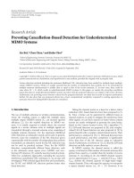
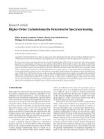
Figure 4 shows simulation results of S parameters at RF
input ports of the proposed multiport circuit. Excellent re-
turn losses and isolation between RF inputs were obtained
in a 2 GHz frequency band centered at the 60 GHz operating
frequency (return loss less than 20 dB).
The phase and the magnitude of the transmission S pa-
rameters are also of main interest to obtain the requested four
“q
i
points” of the multiport circuit (see the block diagram of
Figure 1). Figures 5 and 6 show the phase of transmission
scattering parameters between inputs and outputs versus the
frequency. The phases of these parameters are shifted by 90
multiples over the frequency band, as suggested in the block
diagram.
As suggested in previous figures, the use of the V-band
couplers allows 90
phase difference over a very wide band,
suitable for a high-quality I/Q mixer.
Figure 7 shows the mag nitude of transmission S param-
eters between the RF input port and the four outputs. Com-
pared to the ideal multiport model, a supplementary loss of
around 0.3 dB appears at the central frequency. Similar re-
sults related to the magnitude of transmission S parameters
between the LO input port and the four outputs are also ob-
tained.
59 59.56060.561
Frequency (GHz)
180
90
0
90
180
Phase S parameter (dB)
S
64
S
61
, S
62
180
90
S
63
Figure 6: Simulation results of t he transmission S parameter phase
corresponding to the RF input.
59 59.56060.561
Frequency (GHz)
6.4
6.35
6.3
6.25
6.2
Magnitude S
6i
(dB)
S
61
S
63
S
62
S
64
Figure 7: Simulation results of S
6i
magnitudes at RF input.
0 45 90 135 180 225 270 315 360
Phase difference (deg)
0
0.1
0.2
0.3
0.4
V
out
(V)
v
1
v
2
v
3
v
4
Figure 8: Simulation results of Vout versus inputs phase difference.
In order to demonstrate that the multiport is a four “q
i
-
point” circuit having all points spaced by 90
, a harmonic
balance simulation was performed at 60 GHz using a multi-
port model based on ADS momentum S parameter results.
Power detectors were connected at the four outputs. The
phase difference between millimeter-wave inputs was swept
in a 360
range and the RF input signal power was set to
0 dBm. The multiport output detected voltages versus the
phase difference are shown in Figure 8.
4 EURASIP Journal on Wireless Communications and Networking
Envelope
Envelope
Env 1
Freq[1]
= fr
Order[1]
= 3
Stop
= 1.5 μs
Step
= 0.000025 μs
Var
Eqn
VA R
VA R1
fr
= 60 GHz
ph
= 360 error time
error
= 5MHz
delta
fr = 900 MHz
def
= 0
P
1Tone
PORT2
Num
= 2
Z
= 50 Ohm
P
= polar(dBmtow( 10), ph)
Freq
= fr + delta fr
IQ
ModTuned
MOD1
F
nom
= fr
R
out
= 50 Ohm
MOD
RF
in RF out
I
Q
in
IinQ
+
DT DT
+
P 1Tone
PORT1
Num
= 1
Z
= 50 Ohm
P
= polar(dBmtow(5), 0)
Freq
= fr
VtLFSR DT
SRC1
V
low
= 1V
V
high
= 1V
Rate
= 50 MHz
VtLFSR DT
SRC2
V
low
= 1V
V
high
= 1V
Rate
= 50 MHz
Amplifier
AMP1
S
21
= dBpolar (20, 0)
LOS
Link
LINK1
CenterFreq
= fr
BW
= 1000 MHz
TxGain
= 10 dB
RxGain
= 10 dB
PathLength
= 10 m
PhaseShiftSML
PS1
Phase
= 275
Z
Ref
= 50 Ohm
SP
module SYM
X
1
V
1
V
3
V
4
V
2
OpAmpldeal
AMP2
Gain
= 20
Freq 3 d B
= delta fr
+
+
OpAmpldeal
AMP3
Gain
= 20
Freq 3 d B
= delta fr
Mixer2
MIX2
SideBand
=
Conv Gain = dBpolar (30, 0)
IF
Q
LO
IF
I
LO
Mixer2
MIX3
SideBand =
Conv Gain = dBpolar (30, 0)
PwrSplit2
PWR1
S
21
= 0.707
S
31
= 0.707
LPF
Chebyshev
LPF1
F
pass
= 150 MHz
Ripple
= 1dB
F
stop
= 400 MHz
A
stop
= 20 dB
SampleHoldSML
SAMP1
Q
R
R
1
R = 50 Ohm
R
R
3
R = 50 Ohm
Clock
I
P
1Tone
PORT3
Num
= 3
Z
= 50 Ohm
P
= polar(dBmtow(0), ph)
Freq
= delta fr
Vf
Square
SCR6
Freq
= 100 MHz
Delay
= 0ns
+
LPF Chebyshev
LPF2
F
pass
= 150 MHz
Ripple
= 1dB
F
stop
= 400 MHz
A
stop
= 20 dB
R
R
2
R = 50 Ohm
R
R
4
R = 50 Ohm
SampleHoldSML
SAMP2
+
5
6
2
4
3
1
+
+
Figure 9: ADS simulation block diagram of the multiport heterodyne receiver.
As seen, the output voltage minimum values are shifted
by 90
multiples as requested for this multipor t architecture.
In addition, the output voltages at ports 1 and 3 and at ports
2 and 4, respectively, are in antiphase, as demonstrated in the
theoretical part (see (3)and(4)). Therefore I/Q output sig-
nals can be obtained according to (5) using two differential
amplifiers.
3. DEMODULATION RESULTS
Demodulation results of the V-band multiport heterodyne
receiver are presented in this section.
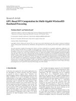
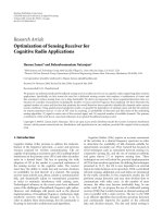
The multiport heterodyne receiver simulation block di-
agram, using ADS software, is presented in Figure 9.Simu-
lations are performed using a 60 GHz carrier frequency of a
MPSK/QAM modulated signal. According to the proposed
datarate of 100–400 Mbps, the IF of the heterodyne receiver
was chosen at 900 MHz. The second frequency conversion
using conventional mixers is also implemented.
As presented in the same figure, the proposed multiport
heterodyne receiver is composed, as usually, of RF, IF, and
baseband stages. The V-band RF front-end contains the low-
noise amplifier AMP1 and the V-band I/Q mixer (the V-band
multiport module including four power detectors).
Excluding the IF differential amplifiers (AMP2 and
AMP3), the IF and baseband stages have a conventional
architecture:IFdown-converters(MIX2,MIX3,LPF1,and
LPF2) and sample-and-hold circuits (SAMP1 and SAMP2).
Baseband amplifiers can be used to improve the overall gain
of the receiver.
In order to obtain the signal waveforms or spectrums,
an ADS envelope simulation at the operating frequency
of 60 GHz is performed using the simulation diagram of
Figure 9. In this diagram a 100 Mbps QPSK pseudorandom
signal is generated at the transmitter using two generators
connected to the I/Q modulator.
Various MPSK/QAM modulations will be also analyzed
in this work using the ADS vector modulator model. It is
noted that a loss-link model based on Friis equation is used
to simulate the free-space signal propagation.
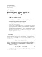
Figure 10 shows the typical IF spectrum (IF
IorIF Qsig-
nals) using the proposed architecture and the same QPSK
signal of 100 Mbps. As well known, and as this spectrum sug-
gested, a 400 Mbps QPSK signal can be demodulated using
the same IF of 900 MHz. However, the bandwidth of the IF
stage must be increased according to the new datarate.
The same architecture can also meet all high-speed re-
quirements of the IEEE 802.15.3c wireless standard using an
increased IF. For this purpose, the IF differential amplifiers
based on operational amplifiers must be replaced by differ-
ential amplifiers using microwave tra nsistors.
Figure 11 shows a typical spectrum of a baseband
quadrature signal (I or Q) obtained after the second down-
conversion and the sample-and-hold circuit (SHC). We note
S. O. Tatu and E. Moldovan 5
1.2 0.9 0.6 0.300.30.60.91.2
Frequency (GHz)
80
70
60
50
40
30
IF signal (dBm)
Figure 10: Typical spectrum of the IF signal.
300 200 100 0 100 200 300
Frequency (MHz)
60
50
40
30
20
10
0
Output signal (dBm)
Figure 11: Typical spectrum of a baseband quadr ature signal.
that the spectral lines of 100 MHz represent the clock signal
of the SHC.
A pseudorandom bit sequence of 700 nanoseconds is
represented in Figure 12. As seen, the demodulated output
signals have the same bit sequence as those generated by the
transmitter. The gray line corresponds to the baseband signal
before the sample-and-hold circuit which dramatically im-
proves the demodulated signal shape.
The demodulation results demonstrate the validity of the
proposed heterodyne architecture. Bit error rate (BER) anal-
ysis is also performed in this work using an appropriated
length pseudorandom bit-stream.
Figure 13 shows all possible 16 states of the I/Q output
signals corresponding to a 16 QAM modulation. As seen,
each signal has four different levels corresponding to the sig-
nal constellation. These levels are quasi-equidistant and sym-
metrical versus the zero voltage level. The gray line has the
same signification as in the previous figure. Therefore, the
SHC improves the demodulation results, as expected.
0 100 200 300 400 500 600 700
Time (ns)
1.5
0.5
0.5
1.5
In I (V)
(a)
0 100 200 300 400 500 600 700
Time (ns)
1.5
0.5
0.5
1.5
Out I (V)
(b)
0 100 200 300 400 500 600 700
Time (ns)
1.5
0.5
0.5
1.5
In Q (V)
(c)
0 100 200 300 400 500 600 700
Time (ns)
1.5
0.5
0.5
1.5
Out Q (V)
(d)
Figure 12: Demodulation results of 100 Mb/s QPSK pseudoran-
dom bit sequence.
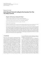
Supposing a perfect synchronism and no additional
noise, Figure 14 shows various simulation results of demod-
ulated constellations using the proposed heterodyne archi-
tecture for high-speed MPSK/QAM signals: 100 Mbps for
QPSK, 200 Mbps for 8PSK and 16 QAM, and 400 Mbps for
16PSK.
As seen, all clusters of demodulated constellations are
very well positioned and individualized. Due to the differ-
ential approach and the multiport design, the DC o ffset rep-
resented by the distance between the central point and the
origin is almost zero.
Figure 15 shows the demodulation results of a 16 QAM
signal for a low signal to noise ratio of 5 dB (a white noise
was added in the transmission path). Simulation results show
that all clusters remain well individualized and well posi-
tioned in the I/Q complex plan. Furthermore, signal process-
ing techniques will allow to obtain improved demodulation
results.
As known, a millimeter-wave oscillator does not have ex-
cellent frequency stability and is difficult to be controlled. If
the difference between the carrier and the local oscillator is
not exactly equal to IF, the demodulated constellation turns
clockwise or anti-clockwise, depending on the sign of this
6 EURASIP Journal on Wireless Communications and Networking
05E81E71.5E 72E72.5E 73E73.5E 7
Time (s)
1.5
1
0.5
0
0.5
1
1.5
Out I (V)
(a)
05E81E71.5E 72E72.5E 73E73.5E 7
Time (s)
1.5
1
0.5
0
0.5
1
1.5
Out Q (V)
(b)
Figure 13: Demodulation results of 16 QAM signal.
difference [9]. Figure 16 shows a 16 QAM constellation in
the case of 45
phase error of synchronism of the mil limeter-
wave oscillator. However, these frequency/phase errors can be
successfully compensated using signal processing techniques.
ThesecondLOmustbedynamicallyadjustedbyacontrol
loop.
Figure 17 shows the BER versus the energy per bit to the
spectr al noise density (Eb/No) for various millimeter-wave
LO frequency errors (no error, 5 MHz, and 25 MHz, resp.).
The frequency/phase error compensation technique of the
second LO in the case of a 100 Mbps QPSK modulated sig-
nal is used. Simulation shows an excellent result for the pro-
posed receiver. The BER is less than 10
6
for an Eb/No ratio
of 12 dB, considering the specified frequency errors of syn-
chronism of the millimeter-wave oscillator.
The heterodyne architecture will allow an increased gain
of the receiver for relatively high range applications com-
pared to the homodyne architecture. Simulation results show
more than 70 dB of the multiport heterodyne receiver overall
gain, compared to 50 dB of gain, reported for the homodyne
receivers [6, 7].
4. CONCLUSIONS
Simulation results of a V-band millimeter-wave multiport
heterodyne receiver have been presented in this paper. The
millimeter-wave frequency conversion is obtained using the
specific properties of the multiport circuit, avoiding the use
of a costly conventional active mixer.
1 0.500.51
I(V)
1
0.5
0
0.5
1
Q(V)
QPSK
(a)
1 0.500.51
I(V)
1
0.5
0
0.5
1
Q(V)
8PSK
(b)
1 0.500.51
I(V)
1
0.5
0
0.5
1
Q(V)
16 PSK
(c)
1.5 0.50.51.5
I(V)
1.5
1
0.5
0
0.5
1
1.5
Q(V)
16 QAM
(d)
Figure 14: Demodulated high-speed MPSK/QAM signals.
1.5 1 0.500.511.5
Out I (V)
1.5
1
0.5
0
0.5
1
1.5
Out Q (V)
Figure 15: Constellation of demodulated 16 QAM signal in pres-
ence of a white noise.
Excellent demodulation results were obtained using
high-speed V-band MPSK/QAM modulated signals. Simu-
lated BER results, in the case of an important millimeter-
wave LO frequency error from synchronism (dynamically
compensated using the second LO), are excellent. Compared
to the direct conversion, due to the heterodyne architecture,
an improved overall gain was obtained.
The proposed multiport heterodyne architecture enables
the design of compact and low-cost wireless millimeter-
wave communication receivers for future high-speed wire-
less communication systems, according to the IEEE 802.15.3c
wireless standard.
S. O. Tatu and E. Moldovan 7
2 1.5 1 0.50 0.51 1.52
Out I (V)
2
1.5
1
0.5
0
0.5
1
1.5
2
Out Q (V)
Figure 16: Constellation of demodulated 16 QAM signal in the
case of 45
phase error of synchronism.
202468101214161820
E
b
/N
o
(dB)
1E
16
1E
15
1E
14
1E
13
1E
12
1E
11
1E
10
1E
9
1E
8
1E
7
1E
6
1E
5
1E
4
1E
3
1E
2
1E
1
1
BER
No error
5MHz
25 MHz
Figure 17: BER simulation results for various errors of synchro-
nism of the millimeter-wave oscillator.
ACKNOWLEDGMENT
The financial support of the National Science Engineer ing
Research Council (NSERC) of Canada is gratefully acknowl-
edged.
REFERENCES
[1] P. Smulders, “Exploiting the 60 GHz band for local wire-
less multimedia access: prospects and future directions,” IEEE
Communications Magazine, vol. 40, no. 1, pp. 140–147, 2002.
[2] J. Wenger and J. Splettstoesser, “K
a
- and V-band MMIC com-
ponents for personal communication networks,” in Proceed-
ings of IEEE MTT-S International Microwave Symposium Di-
gest, vol. 2, pp. 491–494, San Francisco, Calif, USA, June 1996.
[3] A. Nesic, I. Radnovic, and V. Brankovic, “Ultra-wide band
printed antenna array for 60 GHz frequency range,” in Pro-
ceedings of IEEE Antennas and Propagation Society Interna-
tional Symposium Digest, vol. 2, pp. 1272–1275, Montreal,
Quebec, Canada, July 1997.
[4] K. S. Ang, M. Chongcheawchamnan, and I. D. Robertson,
“Monolithic resistive mixers for 60 GHz direct conversion
receivers,” in Proceedings of IEEE Radio Frequency Integrated
Circuits Symposium, Digest of Papers (RFIC ’00), pp. 35–38,
Boston, Mass, USA, June 2000.
[5] T. Brabetz and V. Fusco, “Six-port receiver MMIC for V-band
MBS applications,” in Proceedings of the 11th Gallium Arsenide
Applications Symposium (GAAS ’03), pp. 97–99, Munich, Ger-
many, October 2003.
[6] S. O. Tatu, E. Moldovan, K. Wu, and R. G. Bosisio, “A new
direct millimeter-wave six-port receiver,” IEEE Transactions on
Microwave Theory and Techniques, vol. 49, no. 12, pp. 2517–
2522, 2001.
[7]S.O.Tatu,E.Moldovan,G.Brehm,K.Wu,andR.G.Bosi-
sio, “Ka-band direct digital receiver,” IEEE Transactions on Mi-
crowave Theory and Techniques, vol. 50, no. 11, pp. 2436–2442,
2002.
[8] S. O. Tatu, E. Moldovan, K. Wu, R. G. Bosisio, and T. A.
Denidni, “Ka-band analog front-end for software-defined di-
rect co n v ersion re ceiver,” IEEE Transactions on Microwave The-
ory and Techniques, vol. 53, no. 9, pp. 2768–2776, 2005.
[9] S. O. Tatu and T. A. Denidni, “Millimeter-wave six-port het-
erodyne receiver concept,” in Proceedings of IEEE Microwave
Theory and Techniques Symposium Digest, pp. 1999–2002, San
Francisco, Calif, USA, June 2006, Conference CD, IEEE Cata-
logue Number 06CH37734C.
[10] S. O. Tatu and E. Moldovan, “Alternative millimeter-wave
communication receivers in six-port technology,” in Proceed-
ings of Canadian Conference on Electrical and Computer Engi-
neering (CCECE ’06), Ottawa, Canada, May 2006.