Báo cáo hóa học: " Research Article 60 GHz Indoor Propagation Studies for Wireless Communications Based on a Ray-Tracing Method" docx
Bạn đang xem bản rút gọn của tài liệu. Xem và tải ngay bản đầy đủ của tài liệu tại đây (1.15 MB, 6 trang )
Hindawi Publishing Corporation
EURASIP Journal on Wireless Communications and Networking
Volume 2007, Article ID 73928, 6 pages
doi:10.1155/2007/73928
Research Article
60 GHz Indoor Propagation Studies for Wireless
Communications Based on a Ray-Tracing Method
C P. Lim, M. Lee, R. J. Burkholder, J. L. Volakis, and R. J. Marhefka
ElectroScience Laboratory, Department of Electrical and Computer Engineering, Ohio State University,
1320 Kinnear Road, Columbus, OH 43212, USA
Received 28 April 2006; Revised 13 November 2006; Accepted 13 November 2006
Recommended by Chia-Chin Chong
This paper demonstrates a ray-tracing method for modeling indoor propagation channels at 60 GHz. A validation of the ray-
tracing model with our in-house measurement is also presented. Based on the validated model, the multipath channel parameter
such as root mean square (RMS) delay spread and the fading statistics at millimeter wave frequencies are easily extracted. As
such, the proposed ray-tracing method can provide vital information pertaining to the fading condition in a site-specific indoor
environment.
Copyright © 2007 C P. Lim et al. This is an open access article distributed under the Creative Commons Attribution License,
which permits unrestricted use, distribution, and reproduction in any medium, provided the original work is properly cited.
1. INTRODUCTION
Increasing demand of real-time high-speed applications calls
for wireless local area network (LAN) operating in the
60 GHz band as part of the 4th generation (4G) system. The
60 GHz band has spiked great interest [1–7] because of its
large bandwidth (7 GHz) al located for future dense wireless
local communications, particularly as relates to large wireless
LAN bridges, and wireless high-quality video-conferencing.
To establish such links, wireless systems which exploit time,
frequency, and spatial multiplexing may be required. Design
of these communication systems involves space-time coding,
adaptive antennas, and rake reception which rely strongly
on the characterization of the propagation channel. Previ-
ous work in channel characterizations at these millimeter
(mm) wave frequencies have depended on measurements
[2, 8–11]. However, measurements can be expensive (espe-
cially in the mm-wave band) as compared to electromagnetic
(EM) modeling approaches. Since rigorous numerical meth-
ods are ruled out due to the very short wavelength at mm
waves, we consider high-frequency asymptotic approaches
such as ray-tracing (RT) method for modeling the chan-
nels. RT methods have the capability to solve electrically large
problems relatively fast and, as such, they become an obvious
candidate for the extraction of channel parameters. In this
paper, we compare the channel parameters based on the RT
model with in-house collected measurements, and measure-
ments obtained from [8]. Subsequently, we provide results
for the fading statistics of the received power in two t ypical
indoor propagation channels, namely, within a room and in
ahallway.
The paper is organized as follows. The next section pre-
sents the validation of the ray-tracing model using measure-
ments in the 2-3 GHz band. Section 3 describes the EM mod-
eling of the room and hallway, and the simulation setup. Ex-
traction of the channel parameters and modeling of the fad-
ing statistics are presented in Section 4. Section 5 concludes
the paper.
2. VALIDATION OF THE RAY-TRACING MODEL
WITH MEASUREMENTS
The numerical electromagnetic code-basic scattering code
(NEC-BSC) [12], which is based on 3-dimensional (3D)
ray-tracing technique, utilizes the uniform asymptotic con-
cepts formulated in terms of the uniform geometrical the-
ory of diffraction (UTD) [13, 14]. As such, UTD is ideal
for understanding the high-frequency response of signal in
a complex environment whereby the basic structural fea-
tures (that are crucial for accuracy) of that complex environ-
ment are necessary for modeling. In doing so, this allows for
the use of ray optical techniques for obtaining the incident,
reflected, and diffracted rays, contributed from these vari-
ous basic structures. As a result, the reflected and diffraction
fields are subsequently determined using the UTD solutions
2 EURASIP Journal on Wireless Communications and Networking
Empty room
Bow-tie antenna
Locations where
measurements taken
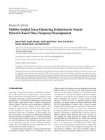
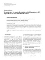
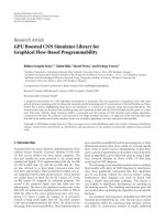
Figure 1: Photograph of the empty room where the measurements
were conducted. The inset shows some of the measuring locations.
which consist of the individual rays that are summed with
the geometrical optics in the far zone of the scatterer. As
we know, the rays from a given scatterer tend to interact
with other nearby objects, resulting into higher-order rays.
As such, NEC-BSC was built to take care of all these high-
order interactions, but not all high-order contributions are
significant. Therefore, one can also choose to include only
dominant contributions in NEC-BSC. Given all these, NEC-
BSC is appropriate in this 60 GHz propagation study and it
is employed to obtain power delay profiles (PDPs) for the in-
door propagation channel. As a first step, we proceed to vali-
date the ray-tracing model with measurements for the indoor
propagation channel considered in this paper.
2.1. Measurement setup
The measurement setup consisted of a network analyzer
(i.e., Agilent E8362B), a pair of 180
◦
hybrid couplers, and
a pair of identical bow-tie antennas (denoted as Antenna
1 and Antenna 2). The bow-tie antennas were designed
to have a center frequency of 2.5 GHz, with fanning an-
gle 45
◦
and 1 GHz bandwidth sufficient for this measure-
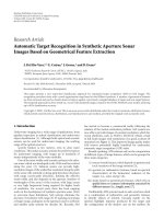
ment. An empty room was chosen (see Figure 1) whose di-
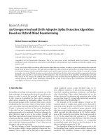
mensions are depicted in Figure 2. Specifically, the room
is of length 7.72 m, width 5.84 m, and height 2.82 m. An-
tenna1, operating as a transmitter, was positioned at (0.94 m,
0.76 m) and at a height of 2.24 m. Antenna 2, serving as
a receiver, was placed at 18 different locations inside the
room (standing at the height of 1.12 m) for measurements.
The detailed position of these 18 locations is depicted in
Figure 2. For consistency, four measurements were taken
at each of these locations and the average of these four
measurements was used as the result. For each measure-
ment, a total of 1601 frequency points (i.e., S
21
)between
2 GHz and 3 GHz was used, resulting in a f requency step of
0.625 MHz. This frequency resolution implied a maximum
excess delay of about 1600 ns and a temporal resolution of
1 ns (because of the 1 GHz bandwidth). We remark that a
signal-to-noise ratio (SNR) of at least 20 dB was maintained
throughout all measurements (via averaging during data
sampling).
2.2. Simulations
For our simulations, the NEC-BSC was used. We computed
the response at the same 1601 continuous wave (CW) tones
evenly spaced between 2 GHz and 3 GHz as done with the
measurements. For these calculations, the direct and re-
flected rays up to tenth order (from the walls, ceiling, and
floor) were included. The walls, floor, and ceiling were char-
acterized by relative dielectric constant
r
= 4.22 − j0.02
whereas the walls were of thickness 14.5 cm. The relative di-
electric constant was taken from the detailed study of mate-
rial characterization (based on measurements) documented
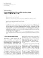
in [15]. Both the transmitting and receiving antennas (i.e.,
Antenna1 and Antenna 2) were modeled in NEC-BSC as hav-
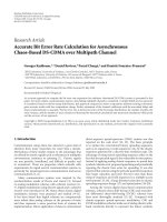
ing a donut antenna pattern as shown in Figure 3. The fig-
ure shows the antenna pattern obtained from Ansoft HFSS
simulation. These antennas (with the same dimensions) were
built and used in our in-house measurements. As such, one
would expect the antenna pattern in the measurements to
be identical to the one obtained in HFSS simulation (refer
to Figure 3). For the propagation study, the similar antenna
pattern was employed in the NEC-BSC simulations. We re-
mark that the simulation time of each location (based on
NEC-BSC) was approximately 139 min using a 1.6 GHz cen-
tral processing unit (CPU) machine.
2.3. Validation results
As is expected, one-to-one mapping of indoor propagation
measurements to simulations is rarely achieved. As such,
one can explore a stochastic way of validating the measure-
ment and simulation data [16]. Specifical ly, we compared the
time-domain multipath channel parameters such as mean
excess delay and root mean square (RMS) delay spread [17].
These parameters are useful in descr ibing the overall char-
acteristics of the multipath profile and are essential in de-
veloping design guidelines for digital wireless communica-
tion systems. These channel parameters are easily extracted
from the power delay profiles (PDPs). To obtain the PDP
at a given receiver location, the 1601 CW tones are trans-
formed to the time domain via an inverse fast Fourier trans-
form (IFFT) procedure. Therefore, each of the 18 measur -
ing locations (see Figure 2) is associated with a PDP and
a set of multipath channel parameters. Of particular im-
portance is the RMS delay spread (σ), which equals to the
square root of the second moment of the PDP [17]. This is
an indicator of the maximum data rate in the wireless chan-
nel and is also directly related to the performance degrada-
tion caused by intersymbol interference (ISI). Given the im-
portance of RMS delay spread, we used this parameter for
comparing the measured and calculated data. As 18 mea-
suring locations were considered here, we built a cumula-
tive distribution function (CDF) for the RMS delay spread
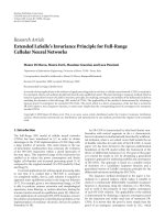
values. Figure 4 shows the measured and simulated RMS de-
lay spread CDFs. Clearly, there is a good agreement between
C P. Lim et al. 3
x
y
0.94 m
0.76 m
T1
Tx height-2.24 m
Rx height-1.12 m
Ceil height-2.82 m
4.27 m
7.72 m
2.84 m
1.42 m
3.86 m 4.83 m
2.9m
1.93 m
0.97 m
2.03 m
0.81 m
4.83 m
3.43 m
5.84 m
R41 R42 R43
R31 R32 R33 R34 R35
R21 R22 R23 R24 R25
R11 R12 R13 R14 R15
Measuring location
Figure 2: The positions of the 18 measuring locations and the transmitting location, all within the classroom of dimensions, length 7.72 m,
width 5.84 m, and height 2.82 m.
y
z
x
Θ
φ
Figure 3: Ansoft HFSS simulation of the bow-tie antennas that were
used for our in-house measurements; on the left is the antenna pat-
tern and on the right is the bow-tie antenna HFSS model.
measurements and simulations, indicating that the NEC-
BSC can be employed for predicting the multipath channel
parameters. As we know, NEC-BSC was formulated based
on UTD concepts which are par ticularly ideal for high-
frequency simulations. As such, one would anticipate when
the ray-tracing modeling was appropriate at 2-3 GHz, it
would also be valid at 60 GHz propagation modeling (since
NEC-BSC employs high-frequency asymptotic approxima-
tions). Next, we proceed with a study at 60 GHz based on
the NEC-BSC.
0
0.2
0.4
0.6
0.8
1
P (RMS delay < abscissa)
0 50 100 150
RMS delay spread (ns)
Simulation
Measurement
Figure 4: Comparison of measured and simulated RMS delay
spread CDFs in the empty room; the solid line denotes the RMS
delay spread obtained from our simulations; the dotted line repre-
sents the measured RMS delay spread.
3. MODELING OF ROOM AND HALLWAY
For our 60 GHz propagation studies, of particular inter-
est was the effect of wall configuration on the channel
parameters and the fading statistics. Thus, we considered two
4 EURASIP Journal on Wireless Communications and Networking
7
4.3
8.4
Ceilings lifted up for illustration
x
y
Transmitter
1
1
7
R13
4.2
3.5
R14
1
1
R11 R12 1
1
0.5
0.5
8.4
(a)
17.4
4.3
54.7
Ceilings lifted up for illustration
x
y
Transmitter
5.8
2.9
8.7
0.526.98.510 0.5
1.4
R24 R23 R22 R21
34.718
54.7
2
(b)
Figure 5: (a) 3D view of the room and its floorplan used for the 60 GHz simulations. (b) 3D view of the hallway and its floorplan. (All
dimensions are in m.)
configurations: (1) a room and (2) a hallway. The dimensions
of the room are depicted in Figure 5(a) and the dimensions
of the hallway are depicted in Figure 5(b). The room has
length 8.4 m, width 7.0 m, and height 4.3 m, whereas the hall-
way has length 54.7 m, width 2.9 m, and height 4.3 m. The
walls, floor, and ceiling are 14.5 cm thick characterized by a
relative dielectric
r
= 4.22− j0.02. For propagation analysis,
we chose a horn antenna as the transmitter with a theoreti-
cal half power beamwidths (HPBW) of 12
◦
in azimuth a nd
9.5
◦
in elevation. The receiving antennas were considered to
have a donut antenna pattern (as shown in Figure 3). We
remark that all receiver positions had a line-of-sight (LOS)
path to the transmitter. Specifically, four receiving locations
for both the room and hallway, namely, R11-R14 and R21-
R24 were sampled (see Figure 5). At these locations, channel
parameters and fading statistics were extracted as described
in Section 4.
For the simulations, the NEC-BSC was set to analyze
the propagation response using 1601 continuous wave (CW)
tones evenly spaced between 59 GHz and 61 GHz, which re-
sults in a frequency sweep with 1.25 MHz steps. As a re-
sult, the frequency resolution had a maximum excess delay
of about 166.66 ns and a temporal resolution of 500 ps (be-
cause of 2 GHz bandwidth). In the simulations, the direct
and reflected rays up to tenth and seventh order from the
walls, ceiling, and floor were included for the room and hall-
way, respectively. Here, our interest is the extraction of the
multipath channel parameter (i.e., RMS delay spread). As
such, the 1601 CW tones are transformed to time domain
to obtain the channel response (i.e., PDP) at each receiver
location. We note that the simulation times for each receiv-
ing location are approximately 67 min and 142 min for the
Table 1: RMS delay spread of room and hallway as shown in
Figure 5.
Rx location
Room
Rx location
Hallway
σ [ns] σ [ns]
R11-(7.4,6.0,1.6) 31.20 R21-(44.2,10.1,1.6) 58.15
R12-(1.0,6.0,1.6) 24.85 R22-(35.7,10.1,1.6) 65.32
R13-(7.4,1.0,1.6) 51.28 R23-(27.4,10.1,1.6) 51.88
R14-(4.2,3.5,1.6) 36.26 R24-(54.2,10.1,1.6) 57.44
room and hallway, respectively, using a 1.6 GHz CPU ma-
chine.
4. CHANNEL PARAMETERS AND FADING MODEL
Next, we proceed to extract the multipath channel parameter
(i.e., RMS delay spread σ) at 60 GHz. Table 1 shows the RMS
delay spread at the various receiving locations for both the
room and the hallway. When the receiving antenna is placed
at different locations, the delay spread ranges from 24.85 ns
to 51.28 ns for the room and from 51.88 ns to 65.32 nsec for
the hallway. The simulated delay spreads are in agreement
with the measurement results in [8]. In the case of [8], the de-
lay spreads for indoor 60 GHz channels range from 15 ns to
45 ns for small rooms and between 30 ns and 70 ns for large
indoor environments. This also implies that the ray-tracing
method can be used to predict the multipath channel param-
eters at the mm-wave frequencies.
As is well known, indoor propagation involves interac-
tions among furniture, walls, or other objects. Because of
C P. Lim et al. 5
0
0.2
0.4
0.6
0.8
1
10 50 510
R11
Room
(a)
0
0.2
0.4
0.6
0.8
1
15 10 50 510
R21
Hallway
(b)
0
0.2
0.4
0.6
0.8
1
15 10 50 510
R12
(c)
0
0.2
0.4
0.6
0.8
1
15 10 50 510
R22
(d)
0
0.2
0.4
0.6
0.8
1
15 10 50 510
R13
(e)
0
0.2
0.4
0.6
0.8
1
15 10 50 51015
R23
(f)
0
0.2
0.4
0.6
0.8
1
15 10 50 51015
R14
Weilbull CDF
Simulations
(g)
0
0.2
0.4
0.6
0.8
1
10 50 5
R24
Weilbull CDF
Simulations
(h)
Figure 6: Cumulative distributive function (CDF) computed from the received power over mean power in Figure 5.ThedotsareCDFof
the simulations of received power over mean power at R11-R14 and R21-24 and the depicted solid lines come from the best-fitted Weibull
distribution.
these multipath, signals arrive at the receiver with different
phases, causing fading. This fading can be obtained statis-
tically from the PDPs by first developing a c umulative dis-
tributive function (CDF) based on the probability of receiv-
ing energies above a predetermined threshold level. Next, we
look for the best-fit distribution for the observed CDF (by
means of maximum likelihood estimation). In this analy-
sis, we chose the Weibull distribution (which has also been
used for ultra-wideband indoor propagation [18]) for fit-
ting the data. The Weibull probability density function can
6 EURASIP Journal on Wireless Communications and Networking
be written as
p(r)
=
⎧
⎪
⎪
⎨
⎪
⎪
⎩
ba
−b
r
b−1
exp
−
r
a
b
for 0 ≤ r ≤∞
0forr<0,
(1)
where a and b, respectively, are the scale and the shape pa-
rameters chosen to fit the simulations.
To check the fitting of the observed and estimated
Weibull data, we performed a null hypothesis testing, H
0
:
(observed data
= fitted Weibull) versus the alternative hy-
pothesis H
A
: (observed data = fitted Weibull) by using the
Kolmogorov-Smirnov (KS) goodness-of-fit test. To ensure a
good fit within a reasonable tolerance, the significant level was
kept within 5%. In both the room and the hallway studies, it
is clearly shown in Figure 6 that the CDFs at receiving lo-
cations (i.e., R11-R14 and R21-R24) have a good agreement
with the Weibull distribution. We remark that the fitness of
our simulations to other CDFs, specifically the Rayleigh CDF,
can be found in [19, 20].
5. CONCLUSION
Based on the 3D ray-tracing method, we extracted statistical
parameters (i.e, RMS delay spread) for indoor site-specific
environments of different configurations. We found that the
fading statistics of these indoor environments were charac-
terized by a Weibull distribution. Accurate prediction of such
statistics is vital in determining the channel capacity, and this
has been shown in [21]. In conclusion, it has been demon-
strated that the r ay-tracing methods can be used for channel
parameter extractions, particularly at 60 GHz band.
ACKNOWLEDGMENTS
The authors would like to thank the editor and the anony-
mous reviewers for their valuable comments and suggestions.
REFERENCES
[1] P. Smulders, “Exploiting the 60 GHz band for local wire-
less multimedia access: prospects and future directions,” IEEE
Communications Magazine, vol. 40, no. 1, pp. 140–147, 2002.
[2] H. Xu, V. Kukshya, and T. S. Rappaport, “Spatial and temporal
characteristics of 60-GHZ indoor channels,” IEEE Journal on
Selected Areas in Communications, vol. 20, no. 3, pp. 620–630,
2002.
[3] T. Manabe, Y. Miura, and T. Ihara, “Effects of antenna direc-
tivity and polarization on indoor multipath propagation char-
acteristics at 60 GHz,” IEEE Journal on Selected Areas in Com-
munications, vol. 14, no. 3, pp. 441–448, 1996.
[4]A.M.HammoudehandG.Allen,“Millimetricwavelengths
radiowave propagation for line-of-sight indoor microcellu-
lar mobile communications,” IEEE Transactions on Vehicular
Technology, vol. 44, no. 3, pp. 449–460, 1995.
[5] S. Collonge, G. Zaharia, and G. El Zein, “Influence of the hu-
man activity on wide-band characteristics of the 60 GHz in-
door radio channel,” IEEE Transactions on Wireless Communi-
cations, vol. 3, no. 6, pp. 2396–2406, 2004.
[6] F. Giannetti, M. Luise, and R. Reggiannini, “Mobile and per-
sonal communications in the 60 GHz band: a survey,” Wireless
Personal Communications, vol. 10, no. 2, pp. 207–243, 1999.
[7] S. K. Yong and C. C. Chong, “An overview of multi-gigabit
wireless through millimeter wave technology: potentials and
technical challenges,” to appear in EURASIP Journal on Wire-
less Communications and Networking.
[8] P. F. M. Smulders and L. M. Correia, “Characterisation of
propagation in 60 GHz radio channels,” Electronics and Com-
munication Engineering Journal, vol. 9, no. 2, pp. 73–80, 1997.
[9] A.Hammoudeh,D.A.Scammell,andM.G.S
´
anchez, “Mea-
surements and analysis of the indoor wideband millimeter
wave wireless radio channel and frequency diversity charac-
terization,” IEEE Transactions on Antennas and Propagation,
vol. 51, no. 10 II, pp. 2974–2986, 2003.
[10] N. Moraitis and P. Constantinou, “Indoor channel measure-
ments and characterization at 60 GHz for wireless local area
network applications,” IEEE Transactions on Antennas and
Propagation, vol. 52, no. 12, pp. 3180–3189, 2004.
[11] T. Zwick, T. J. Beukema, and H. Nam, “Wideband channel
sounder with measurements and model for the 60 GHz in-
door radio channel,” IEEE Transactions on Vehicular Technol-
ogy, vol. 54, no. 4, pp. 1266–1277, 2005.
[12] R. J. Marhefka, “Numerical electromagnetics code - basic scat-
tering code (NEC-BSC Version 4.2), User’s Manual,” Tech.
Rep. (Preliminary), ElectroScience Laboratory, The Ohio State
University, Columbus, Ohio, USA, October 2000.
[13] R G. Kouyoumjian and P. H. Pathak, “A uniform geometrical
theory of diffraction for an edge in a perfectly conducting sur-
face,” Proceedings of the IEEE, vol. 62, no. 11, pp. 1448–1461,
1974.
[14] P. H. Pathak, W. D. Burnside, and R. J. Marhefka, “A Uniform
GTD analysis of the diffraction of electromagnetic waves by
a smooth convex surface,” IEEE Transactions on Antennas and
Propagation, vol. 28, no. 5, pp. 631–642, 1980.
[15] A. H. Muqaibel, “Characterization of ultra wideband com-
munication channels,” Ph.D. dissertation, Virginia Polytech-
nic Institute and State University, Blacksburg, Va, USA, 2003.
[16] C C. Chong, Y E. Kim, S. K. Yong, and S S. Lee, “Statistical
characterization of the UWB propagation channel in indoor
residential environment,” Wireless Communications and Mo-
bile Computing, vol. 5, no. 5, pp. 503–512, 2005, special issue
on Ultrawideband for Wireless Communications.
[17] T. S. Rappaport, Wireless Communications: Principles and Prac-
tice, Prentice-Hall, Upper Saddle River, NJ, USA, 1996.
[18] C C. Chong and S. K. Yong, “A generic statistical-based UWB
channel model for high-rise apartments,”
IEEE Transactions
on Antennas and Propagation, vol. 53, no. 8, part 1, pp. 2389–
2399, 2005.
[19] R. J M. Cramer, R. A. Scholtz, and M. Z. Win, “Evaluation of
an ultra-wide-band propagation channel,” IEEE Transactions
on Antennas and Propagation, vol. 50, no. 5, pp. 561–570, 2002.
[20] C P.Lim,R.J.Burkholder,J.L.Volakis,andR.J.Marhefka,
“Propagation modeling of indoor wireless communications
at 60GHz,” in Proceedings of IEEE AP-S International Sym-
posium and USUC/URSI National Radio Science Meeting and
AMEREM Meeting, pp. 2149–2152, Albuquerque, NM, USA,
July 2006.
[21] C P. Lim, J. L. Volakis, K. Sertel, R. W. Kindt, and A.
Anastasopoulos, “Indoor propagation models based on rigor-
ous methods for site-specific multipath environments,” IEEE
Transactions on Antennas and Propagation,vol.54,no.6,pp.
1718–1725, 2006.