Báo cáo hóa học: " Research Article Low-Complexity Multiple Description Coding of Video Based on 3D Block Transforms" ppt
Bạn đang xem bản rút gọn của tài liệu. Xem và tải ngay bản đầy đủ của tài liệu tại đây (957.51 KB, 11 trang )
Hindawi Publishing Corporation
EURASIP Journal on Embedded Systems
Volume 2007, Article ID 38631, 11 pages
doi:10.1155/2007/38631
Research Article
Low-Complexity Multiple Description Coding of
Video Based on 3D Block Transforms
Andrey Norkin, Atanas Gotchev, Karen Egiazarian, and Jaakko Astola
Institute of Signal Processing, Tampere University of Technology, P.O. Box 553, 33101 Tampere, Finland
Received 28 July 2006; Revised 10 January 2007; Accepted 16 January 2007
Recommended by Noel Oconnor
The paper presents a multiple description (MD) video coder based on three-dimensional (3D) transforms. Two balanced descrip-
tions are created from a video sequence. In the encoder, video sequence is represented in a form of coarse sequence approximation
(shaper) included in both descriptions and residual sequence (details) which is split between two descriptions. The shaper is ob-
tained by block-wise pruned 3D-DCT. The residual sequence is coded by 3D-DCT or hybrid, LOT+DCT, 3D-transform. The
coding scheme is targeted to mobile devices. It has low computational complexity and improved robustness of t ransmission over
unreliable networks. The coder is able to work at very low redundancies. The coding scheme is simple, yet it outperforms some
MD coders based on motion-compensated prediction, especially in the low-redundancy region. The margin is up to 3 dB for re-
construction from one description.
Copyright © 2007 Andrey Norkin et al. This is an open access article distributed under the Creative Commons Attribution License,
which permits unrestricted use, distribution, and reproduction in any medium, provided the original work is properly cited.
1. INTRODUCTION
Nowadays, video is more often being encoded in mobile
devices and transmitted over less reliable wireless chan-
nels. Traditionally, the objective in video coding has been
to achieve high compression, which was attained with the
cost of increasing encoding complexity. However, portable
devices, such as camera phones, still lack enough computa-
tional power and are energy-consumption constrained. Be-
sides, a highly compressed video sequence is more vulnera-
ble to transmission errors, which are often present in wireless
networks due to multipath fading, shadowing, and environ-
mental noise. Thus, there is a need of a low-complexity video
coder with acceptable compression efficiency and strong
error-resilience capabilities.
Lower computational complexity in tr ansform-based
video coders can be achieved by properly addressing the mo-
tion estimation problem, as it is the most complex part of
such coders. For the case of high and moderate frame rates
ensuring smooth motion, motion-compensated (MC) pre-
diction can be replaced by a proper transform along the tem-
poral axis to handle the temporal correlation between frames
in the video sequence. Thus, the decorrelating transform
adds one more dimension, becoming a 3D one, and if a low
complexity algorithm for such a transform exists, savings in
overall complexity and power consumption can be expected
compared to traditional video coders [1–4]. Discrete cosine
transform (DCT) has been favored for its very efficient 1D
implementations. As DCT is a separable transform, efficient
implementations of 3D-DCT can be achieved too [2, 3, 5].
Previous research on this topic shows that simple (baseline)
3D-DCT video encoder is three to four times faster than the
optimized H.263 encoder [6],forthepriceofsomecompres-
sion efficiency loss, quite acceptable for portable devices [7].
A 3D-DCT video coder is also advantageous in terms
of error resilience. In MC-based coders, the decoding error
would propagate further into subsequent frames until the
error is corrected by an intracoded frame. The error could
also spread over the bigger frame area because of motion-
compensated prediction. Unlike MC-based coders, 3D-DCT
video coders enjoy no error propagation in the subsequent
frames. Therefore, we have chosen the 3D-DCT video coding
approach for designing a low-complexity video coder with
strong error resilience.
A well-known approach addressing the source-channel
robustness problem is so-called multiple description cod-
ing (MDC) [8]. Multiple encoded bitstreams, called descrip-
tions, are generated from the source information. They are
correlated and have similar importance. The descriptions are
independently decodable at the basic quality level and, when
several descriptions are reconstructed together, improved
2 EURASIP Journal on Embedded Systems
3D-DCT
16
× 16 × 16
3D-IDCT
16
× 16 × 16
Transform
8
× 8 × 8
Deblock
filter
+
−
Video
sequence
Thres-
holding
Zero-
padding
Blocks
splitting
Q
s
IQ
s
Q
r
Entropy
coding
Entropy
coding
Entropy
coding
X
s
X
1
X
2
Description 1
Description 2
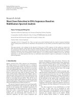
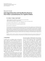
Figure 1: Encoder scheme.
quality is obtained. The advantages of MDC are strength-
ened when MDC is connected with multipath (multichan-
nel) transport [9]. In this case, each bitstream (description) is
sent to the receiver over a separate independent path (chan-
nel), which increases the probability of receiving at least one
description.
Recently, a great number of multiple description (MD)
video coders have appeared, most of them based on MC pre-
diction. However, MC-based MD video coders risk having a
mismatch between the prediction loops in the encoder and
decoder when one description is lost. The mismatch could
propagate further in the consequent frames if not corrected.
In order to prevent this problem, three separate prediction
loops are used at the encoder [10] to control the mismatch.
Another solution is to use a separate prediction loop for
every description [11, 12]. However, both approaches de-
crease the compression efficiency and the approach in [10]
also leads to increased computational complexity and possi-
bly to increased power consumption. A good review of MDC
approaches to video coding is given in [13]. A number of
MD and error-resilient video coders based on 3D transforms
(e.g., wavelets, lapped orthogonal transforms (LOT), DCT)
have been proposed [14–17].
In this work, we investigate a two-stage multiple de-
scription coder based on 3D transforms, denoted by 3D-
2sMDC. This coder does not exploit motion compensation
as initially proposed in [18]. Using 3D transform instead of
motion compensated prediction reduces the computational
complexity of the coder, meanwhile eliminating the problem
of mismatch between the encoder and decoder. The proposed
MD video coder is a gener alization of our 2-stage image MD
coding approach [19] to coding of video sequences [18]. De-
signing the coder, we are targeting balanced computational
load between the encoder and decoder. The coder should be
able to work at a very low redundancy introduced by MD
coding and be competitive with MD video coders based on
motion-compensated prediction.
The paper is organized as fol lows. Section 2 overviews the
encoding and decoding processes in general while Section 3
describes each block of the proposed scheme in detail.
Section 4 presents the analysis of the proposed scheme and
Section 5 discusses its computational complexity. Section 6
offers a packetization strategy; Section 7 presents the simula-
tion results; while Section 8 concludes the paper.
2. GENERAL CODING SCHEME
2.1. Encoder operation
In our scheme, a video sequence is coded in two stages as
shown in Figure 1. In the first stage (dashed rectang le), a
coarse sequence approximation, called shaper, is obtained
and included in both descriptions. The second stage pro-
duces enhancement information, which has higher bitrate
and is split between two descriptions. The idea of the method
is to get a coarse signal approximation which is the best pos-
sible for the given bitrate while decorrelating the residual se-
quence as much as possible.
The operation of the proposed encoder is described in the
following. First, a sequence of frames is split into groups of 16
frames. Each group is split into 3D cubes of size 16
× 16 × 16.
3D-DCT is applied to each cube. The lower-frequency DCT
coefficients in the 8
× 8 × 8 cube are coarsely quantized with
quantization step Q
s
and entropy-coded (see Figure 2(a))
composing the shaper, other coefficients are set to zero. In-
verse quantization is applied to these coefficients followed
by the inverse 3D-DCT. An optional deblocking filter serves
to remove the block edges in spatial domain. Then, the se-
quence reconstructed from the shaper is subtracted from the
original sequence to get the residual sequence.
The residual sequence is coded by a 3D block transform
and transform coefficients are finely quantized with a uni-
form quantization step ( Q
r
), split into two parts in a manner
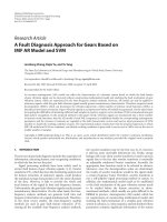
shown in Figure 2(b), and entropy-coded. One part together
with the shaper forms Description 1, while the second part
combined again with the shaper forms Description 2.Thus,
each description consists of the shaper and half of the trans-
form volumes of the residual sequence.
Andrey Norkin et al. 3
DC
8
8
8
16
16
16
(a)
t
8
8
8
(b)
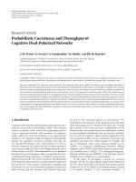
Figure 2: Coding patterns: (a) 3D-D CT cube for shaper coding:
only coefficients in the gray volumes are coded, other coefficients
are set to zero; (b) split pattern for volumes of a residual sequence:
“gray”-Description 1; “white”-Description 2.
The shaper is included in both descriptions to facilitate
successful reconstruction when one description is lost. Thus,
the redundancy of the proposed coder is only determined by
the shaper quality, which is controlled by the shaper quan-
tization step Q
s
. A larger quantization step corresponds to
lower level of redundancy and lower quality of side recon-
struction (reconstruction from only one description). Alter-
natively, a smaller quantization step results in higher-quality
side reconstruction. The quality of the two-channel recon-
struction is controlled by the quantization step Q
r
used in
the coding of the residual sequence. As the residual vol-
umes are divided into two equal parts, the encoder pro-
duces balanced descriptions both in terms of PSNR and bi-
trate.
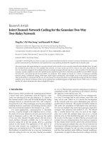
2.2. Decoder operation
The decoder (see Figure 3) operates as follows. When the de-
coder receives two descriptions, it extracts the shaper (X
s
)
from one of the descriptions. Then, the shaper is entropy-
decoded and inverse quantization is applied. The 8
× 8 × 8
volume of coefficients is zero-padded to the size 16
× 16× 16,
and inverse DCT is applied. The deblocking filter is applied
if it was applied in the encoder.
In case of central reconstruction (reconstruction from
two descriptions), each part of the residual sequence (X
1
and
X
2
) is extracted from the corresponding description a nd en-
tropy decoded. Then, volumes of the corresponding descrip-
tions are decoded and combined together as in Figure 2(b).
The inverse quantization and i nverse transform (IDCT or
Hybrid inverse transform ) are applied to coefficients and the
residual sequence is added to the shaper to obtain the recon-
struction of the original sequence.
We term the reconstruction from one description, for
example, Description 1,asside reconstruction (reconstruc-
tion from Description 2 is symmetrical). The side decoder
scheme can be obtained from Figure 3 if the content of the
dashed rectangle is removed. In this case, the shaper is recon-
structed from its available copy in Description 1. The residual
sequence, however, has only half of the coefficient volumes
(X
1
). The missing volumes X
2
are simply filled with zeros. Af-
ter that, the decoding process is identical to that of the central
reconstruction. As the residual sequence has only half of the
coefficient volumes, the side reconstruction has lower, how-
ever, still acceptable quality. For example, sequence “silent
voice” coded at 64.5 kbps with 10% redundancy can be re-
constructed with PSNR
= 31.49 dB from two descriptions,
and 26.91 dB from one description (see Table 2).
3. DETAILED SYSTEM DESCRIPTION
3.1. The coarse sequence approximation
The idea of the first coding stage is to concentrate as much
information as possible into the shaper within strict bitrate
constraints. We would also like to reduce artifacts and dis-
tortions appearing in the reconstructed coarse approxima-
tion. The idea is to reduce spatial and temporal resolutions
of the coarse sequence approximation in order to code it
more efficiently with lower bitrate [20]. Then, the original
resolution sequence can be reconstructed by interpolation
as a post-processing step. A good interpolation and deci-
mation method would concentrate more information in the
coarse approximation and correspondingly make the resid-
ual signal closer to white noise. A computationally inexpen-
sive approach is to embed interpolation in the 3D trans-
form.
The downscaling factor for the shaper was chosen equal
to two in both spatial and temporal directions. The proposed
scheme is able to use other downscaling factors equal to pow-
ers of two. However, the downscaling factor two has been
chosen as the one producing the best results for QCIF and
CIF resolutions. To reduce computational complexity, we
combine downsampling with forward transform (and back-
ward transform with interpolation). Thus, the original se-
quence is split into volumes of size 16
× 16 × 16, and 3D-
DCT is applied to each volume. Pruned DCT is used in this
stage that allows to reduce computational complexity (see
Figure 2(a)). The transform size of 16
× 16 × 16 has been
chosen as a compromise between the compression efficiency
and computational complexity.
Only 8
× 8× 8 cubes of low-frequency coefficients in each
16
× 16 × 16 coefficient volume are used; other coefficients
are set to zero (see Figure 2(a)). The AC coefficients of the
8
× 8 × 8 cube are uniformly quantized with quantization
step Q
s
.DCcoefficients are quantized with the quantization
step Q
DC
.
In the 8
× 8 × 8 volume, we use coefficient scanning de-
scribed in [21], which is similar to a 2D zigzag scan. Although
there exist more advanced types of quantization and scan-
ning of 3D volumes [1, 22], we have found that simple scan-
ning performs quite well. An optional deblocking filter may
be used to eliminate the blocking ar tifacts caused by quanti-
zation and coefficient thresholding.
The DC coefficients of the transformed shaper volumes
are coded by DPCM prediction. The DC coefficient of the
volume is predicted from the DC coefficient of the tempo-
rally preceding volume. As the shaper is included in both de-
scriptions, there is no mismatch between the states of the en-
coder and decoder when one description is lost.
4 EURASIP Journal on Embedded Systems
3D-IDCT
16
× 16 × 16
Description 1
Description 2
X
s
X
1
X
2
X
s
Entropy
decoding
Entropy
decoding
Entropy
decoding
IQ
s
Zero-
padding
Deblock
filter
Blocks
filling
IQ
r
Inverse
transform
8
× 8 × 8
+
Reconstructed
sequence
Figure 3: Decoder scheme. Central reconstruction. Side reconstruction (Description 1) when the content of the dashed rectangle is removed.
First, the DC coefficient prediction errors and the AC co-
efficients undergo zero run-length (RL) encoding. It com-
bines runs of successive zeros and the follow ing nonzero co-
efficients into two-tuples where the first number is the num-
ber of leading zeros, and the second number is the absolute
value of the first nonzero coefficient following the zero-run.
Variable-length encoding is implemented as a standard
Huffman encoder similar to the one in H.263 [6]. The code-
book has the size 100 and is calculated for the two tuples
which are the output of RL-coding. All values exceeding the
range of the codebook are encoded with an “escape” code fol-
lowed by the actual value. Two different codebooks are used:
one for coding the shaper and another for coding the residual
sequence.
3.2. Residual sequence coding
The residual sequence is obtained by subtracting the recon-
structed shaper from the original sequence. As the residual
sequence consists of high-frequency details, we do not add
any redundancy at this stage. The residual sequence is split
into groups of 8 frames in such a way that two groups of
8 frames correspond to one group of 16 frames obtained
from the coarse sequence approximation. Each group of 8
frames undergoes block 3D transform. The transform coef-
ficients are uniformly quantized with the quantization step
Q
r
and split between two descriptions in a pattern show n in
Figure 2(b).
Two di fferent transforms are used in this work to code
the residual sequence. The first transform is 3D-DCT and the
second is a hybrid transform. The latter consists of the lapped
orthogonal transform (LOT) [23] in vertical and horizontal
directions, and DCT in temporal direction. Both DCT and
the hybrid transform produce 8
× 8 × 8volumesofcoeffi-
cients, which are split between the two descriptions. Using
LOT in spatial domain smoothes blocking artifacts when re-
constructing from one description. In this case, LOT spa-
tially spreads the error caused by loosing transform coeffi-
cient blocks. Although LOT could be applied in the tempo-
ral direction to reduce blocking artifacts in temporal domain
too, we avoid using it because of additional delay it intro-
duces in the encoding and decoding processes.
As will be demonstrated in Section 7, the hybrid trans-
form outperforms DCT in terms of PSNR and visual quality.
Moreover, using LOT in spatial dimensions gives better vi-
sual results compared to DCT. However, blocking artifacts
introduced by coarse coding of the shaper are not completely
concealed by the residual sequence coded with the hybrid
transform. These artifacts impede efficient compression of
the residual sequence by the hybrid transform. Therefore, the
deblocking filter is applied to the reconstructed shaper (see
Figure 1) prior to subtracting it from the original sequence.
In the experiments, we use the deblocking filter from H.263+
standard [6].
In the residual sequence coding, the transform coeffi-
cients are uniformly quantized with the quantization step Q
r
.
DC prediction is not used in the second stage to avoid the
mismatch between the states of the encoder and decoder if
one description is lost. The scanning of coefficients is 3D-
zigzag scanning [21]. The entropy coding is RL coding fol-
lowed by Huffman coding with a codebook different from
the one used in coding the coarse sequence approximation.
4. SCHEME ANALYSIS
4.1. Redundancy and reconstruction quality
Denote by D
0
the central distortion (distortion when recon-
structing from two descriptions), and by D
1
and D
2
the side
distortions (distortions when reconstructing from only one
description). In case of balanced descriptions, D
1
= D
2
.De-
note as D
s
the distortion of the video sequence reconstructed
only from the shaper. Consider 3D-DCT coding of the resid-
ual sequence. The side distortion D
1
is formed by the blocks,
half of which are coded with the distor tion D
0
, and half with
the shaper distortion D
s
.Hereweassumethatallblocksof
Description 1 have the same expected distort ion as blocks of
Description 2. Consequently,
D
1
=
1
2
D
s
+ D
0
. (1)
Expression (1) can also be used in case the hybrid transform
is used for coding the residual. As LOT is by definition an or-
thogonal transform, mean-squared error distortion in spatial
domain is equal to the distortion in the transform domain.
Andrey Norkin et al. 5
The side distortion in the transform domain is determined by
loosing half of the transform coefficient blocks. Thus, expres-
sion (1) is also valid for hybrid transform. It is obvious that
D
s
depends on the bitrate R
s
allocated to the shaper. Then,
we can write (1)as
D
1
R
s
, R
r
=
1
2
D
s
R
s
+ D
0
R
r
, R
s
,(2)
where R
r
is the bitrate allocated for coding the residual se-
quence and R
s
is the bitrate allocated to the shaper. For higher
bitrates, D
s
(R
s
) D
0
(R
r
), and D
1
mostly depends on R
s
.
The redundancy ρ of the proposed scheme is the bitrate
allocated to the shaper, ρ
= R
s
. The shaper bitrate R
s
and
the side reconstruction distortion D
1
depend on the quanti-
zation step Q
s
and the characteristics of the video sequence.
The central reconstruction distortion D
0
is mostly deter-
mined by the quantization step Q
r
.
Thus, the encoder has two control parameters: Q
s
and Q
r
.
By changing Q
r
, the encoder controls the central distortion.
By changing Q
s
, the encoder controls the redundancy and the
side distortion.
4.2. Optimization
The proposed scheme can be optimized for changing channel
behavior. Denote by p the probability of the packet loss and
by R the target bitrate. Then, in case of balanced descriptions
we have to minimize
2p(1
− p)D
1
+(1− p)
2
D
0
(3)
subject to
2R
s
+ R
r
≤ R. (4)
Taking into consideration (1), expression (3) can be tr ans-
formed to the unconstrained minimization task
J
R
s
, R
r
=
p(1 − p)
D
s
R
s
+ D
0
R
s
, R
r
+(1− p)
2
D
0
R
s
, R
r
+ λ
2R
s
+ R
r
− R
.
(5)
It is not feasible to find the distortion-rate functions D
0
(R
s
,
R
r
)andD
s
(R
s
) in real-time to solve the optimization task.
Instead, the distortion-rate (D-R) function of a 3D coder can
be modeled as
D(R)
= b2
−aR
− c,(6)
where a, b,andc are parameters, which depend on the char-
acteristics of the video sequence. Hence,
D
s
R
s
=
b2
−aR
s
− c. (7)
Assuming that the source is successively refinable in regard
to the squared-error distortion measure (this is true, e.g ., for
i.i.d. Gaussian source [24]) we can write
D
0
R
s
, R
r
=
b2
−a(R
s
+R
r
)
− c. (8)
Then, substituting (7)and(8) into (5) and differentiating the
resulting Lagrangian with respect to R
s
, R
f
,andλ,wecan
find a closed form solution of the optimization task (5). The
obtained optimal values of bitrates R
s
and R
r
are
R
∗
s
=
1
2
R +
1
2a
log
2
(p),
R
∗
r
=−
1
a
log
2
(p),
(9)
where R
∗
s
and R
∗
r
are rates of the shaper and the residual se-
quence, respectively.
Hence, the optimal redundancy ρ
∗
of the proposed
scheme under above assumptions is
ρ
∗
= R
∗
s
=
1
2
R +
1
2a
log
2
(p). (10)
The optimal redundancy ρ
∗
depends on the target bitrate R,
the probability of packet loss p, and parameter a of the source
D-R function. It does not depend on D-R parameters b and
c.Wehavefoundthatparametera usually takes similar val-
ues for video sequences with the same resolution and frame
rates. Thus, one does not need to estimate a in real-time. In-
stead,onecanuseatypicalvalueofa to perform optimal bit
allocation during encoding. For example, sequences with CIF
resolution and 30 frames per second usually have the value of
a between 34 and 44 for bitrates under 1.4 bits per pixel.
One notices that for values R and p such that R
≤
−
(1/a)log
2
(p), the optimal redundancy ρ
∗
is zero or neg-
ative. For these values of R and p, the encoder should not use
MDC. Instead, single description coding should be used. It
is seen from (10) that the upper limit for redundancy is R/2,
which is obtained for p
= 1. That means that all the bits are
allocated to the shaper, which is duplicated in both descrip-
tions.
5. COMPUTATIONAL COMPLEXITY
To perform a 3D-DCT of an N
× N × N cube, one has to per-
form 3N
2
one-dimensional DCTs of size N.However,ifone
needs only the N/2
× N/2 × N/2 low-frequency coefficients,
as in the case of the shaper coding, a smaller amount of DCTs
need to be computed. Three stages of separable row-column-
frame (RCF) transform require [N
2
+1/2N
2
+1/4N
2
] =
1.75N
2
DCTs for one cube. The same is true for the inverse
transform.
The encoder needs only the 8 lowest coefficients of 1D-
DCT. For this reason, we use pruned DCT as in [25]. The
computation of the 8 lowest coefficients of pruned DCT II
[26] of size 16 requires 24 multiplications and 61 additions
[25]. That gives 2.625 multiplications and 6.672 additions
per point and brings substantial reduction in computational
complexity. For comparison, full separable DCT II ( decima-
tion in frequency (DIF) algorithm) [26] of size 16 would re-
quire 6 multiplications and 15.188 additions per point.
The operation count for different 3D-DCT schemes is
provided in Tabl e 1 . The adopted “pruned” algorithm is
compared to fast 3D vector-radix decimation-in-frequency
DCT (3D VR DCT) [5] and row-column-frame (RCF) ap-
proach, where 1D-DCT is computed by DIF algorithm [26].
One can see that the adopted “pruned” algorithm has the
6 EURASIP Journal on Embedded Systems
Table 1: Operations count for 3D-DCT II. Comparison of algorithms.
Transform
Pruned 3D VR RCF 3D VR RCF
16 × 16 × 16 16 × 16 × 16 16 × 16 × 16 8 × 8 × 88× 8 × 8
Mults/point 2.625 3.5 6 2.625 4.5
Adds/point
6.672 15.188 15.188 10.875 10.875
Mults+adds/point
9.297 18.688 21.188 13.5 15.375
lowest computational complexity. In terms of operations per
pixel, partial DCT 16
× 16 × 16 is less computationally ex-
pensive than full 8
× 8 × 8 DCT used to code the residual
sequence.
In [7], a baseline 3D-DCT encoder is compared to the
optimized H.263 encoder [27]. It was found [7] that base-
line 3D-DCT encoder is up to four times faster than the
optimized H.263 encoder. In the baseline 3D-DCT encoder
[7], DCT was implemented by RCF approach, which gives
15.375 operations/point. In our scheme, forward pruned 3D-
DCT for the shaper requires only 9.3 op/point. Adding the
inverse transform, one gets 18.6 op/points. The 8
× 8 × 8
DCT of the residual sequence can be implemented by 3D
VR DCT [5], which requires 13.5 op/point. Thus, the overall
complexity of the transforms used in the proposed encoder
is estimated as 32.1 op/point, that is about twice higher than
the complexity of the transforms used in baseline 3D-DCT
(15.375 op/point).
The overall computational complexity of the encoder in-
cludes quantization and entropy coding of the shaper coef-
ficients. However, the number of coefficients coded in the
shaper is eight times lower than the number of coefficients
in the residual sequence as only 512 lower DCT coefficients
in each 16
× 16 × 16 block are coded. Thus, quantization and
entropy coding of the shap er would take about 8 times less
computations than quantization and entropy coding of the
residual sequence. Thus, we estimate that the overall com-
plexity of the proposed encoder is not more than twice the
complexity of baseline 3D-DCT [7]. This means that the
proposed coder has up to two times lower-computational
complexity than the optimized H.263 [27]. The difference in
computational complexity between the proposed coder and
H.263+ with scalability (providing error resilience) is even
bigger. However, the proposed coder has single description
performance similar or even higher than H.263+ [6]with
SNR scalability, as shown in Section 7.
6. PACKETIZATION AND TRANSMISSION
The bitstream of the proposed video coder is packetized as
follows. A g roup of pictures (16 frames) is split into 3D-
volumesofsize16
× 16 × 16. One packet should contain one
or more shaper volumes, which gives 512 entropy-coded co-
efficients (due to thresholding).
In case of single description coding, one shaper volume
is followed by eight spatially corresponding volumes of the
residual sequence, which have the size of 8
× 8 × 8. In case
of multiple description coding, a packet from Description 1
contains a shaper volume and four residual volumes taken
in the pattern shown in Figure 2(b). Description 2 contains
the same shaper volume and four residual volumes, which
are not included into Description 1. If the size of such a block
(one shaper volume and four residual volumes) is small, sev-
eral blocks are packed into one packet.
The proposed coder uses DPCM prediction of DC co-
efficients in the shaper volumes. The DC coefficient is pre-
dicted from the DC coefficient of the temporally preceding
volume. If both descriptions containing the same shaper vol-
ume are lost, DC coefficient is estimated as the previous DC
coefficient in the same spatial location or as an average of
DC coefficients of the spatially adjacent volumes. This con-
cealment may introduce mismatch in DPCM loop between
the encoder and decoder. However, the mismatch does not
spread out of the border of this block. The mismatch is cor-
rected by the DC coefficient u pdate which can be requested
over a feedback channel or may be done periodically.
To further improve the robustness against burst errors,
the bitstream can be reordered in a way that descriptions cor-
responding to one 3D volume are transmitted in the pack-
ets which are not consecutive. It will decrease the probabil-
ity that both descriptions are lost due to consequent packet
losses. Another solution to improve the error resilience is to
send the packets of Description 1 over one link, and packets
from Description 2 over another link.
7. SIMULATION RESULTS
This section presents the comparison of the proposed MD
coder with other MD coders. The experiments are performed
onsequences“Tempete”(CIF,30fps,10s),“silentvoice”
(QCIF, 15 fps, 10 s), and “Coastguard” (CIF, 30 fps). We mea-
sure the reconstruction quality by using the peak signal-
to-noise ratio (PSNR). The distortion is average luminance
PSNR over time, all color components are coded. We com-
pare our scheme mainly with H.263-based coders as our
goal is low-complexity encoding. Apparently, the proposed
scheme cannot compete with H.264 in terms of compression
performance. H owever, H.264 encoders are much more com-
plex.
7.1. Single description performance
Figure 4 plots PSNR versus bitrate for the sequence “Tem-
pete.” The compared coders are single description coders.
“3D-2stage” coder is a single-description variety of the coder
described above. The shaper is sent only once, and the
residual sequence is sent in a single description. “3D-DCT”
is a simple 3D-DCT coder described in [1, 7]. “H.263”
is a Telenor implementation of H.263. “H.263-SNR” is an
H.263+ with SNR scalability, implemented at the University
Andrey Norkin et al. 7
24
26
28
30
32
34
PSNR (dB)
0 500 1000 1500 2000 2500
3D-2stage
3D-DCT
H.263
H.263-SNR
Bitrate (kbps)
Figure 4: Sequence “Tempete,” single description coding.
of British Columbia [28, 29]. One can see that H.263 coder
outperforms other coders. Our 3D-2stage has approximately
the same performance as H.263+ with SNR scalability and
its PSNR is half to one dB lower than that of H.263+. Simple
3D-DCT coder showed the worst performance.
Figure 5 shows PSNR of the first 100 frames of “Tempete”
sequence. The sequence is encoded to target bitrate 450 kbps.
Figure 5 demonstrates that 3D-DCT coding exhibits tempo-
ral degradation of quality on the borders of 8-frame blocks.
These temporal artifacts are caused by block-wise DCT and
perceived like abrupt movements. These artifacts can be effi-
ciently concealed with postprocessing on the decoder side. In
this experiment, we applied MPEG-4 deblocking filter [30]
to block borders in temporal domain. As a result, temporal
artifacts are smoothed. The perceived quality of the video
sequence has also improved. Some specialized methods for
deblocking in temporal domain can be applied as in [31].
Postprocessing in temporal and spatial domains can also im-
prove reconstruction quality in case of description loss. In
the following experiments, we do not use postprocessing
in order to have fair comparison with other MDC meth-
ods.
7.2. Performance of different residual coding methods
In the following, we compare the performance of MD coders
in terms of side reconstruction distortion, w h ile they have
the same central distortion. Three variants of the proposed
3D-2sMDC coder are compared. These MD coders use dif-
ferent schemes for coding the residual sequence. “Scheme
1” is the 2-stage coder, which uses hybrid transform for the
residual sequence coding and the deblocking filtering of the
shaper. “Scheme 2” employs DCT for coding the residual se-
quence. “Scheme 3” is similar to “Scheme 2” except that it
25.5
26
26.5
27
27.5
28
28.5
PSNR (dB)
0 20 40 60 80 100
3D-2stage
3D-2stage postprocessing
H.263
H.263-SNR
Frames
Figure 5: Sequence “ Tempete” coded at 450 kbps, single description
coding.
uses the deblocking filter (see Figure 1). We have compared
these schemes with simple MD coder based on 3D-DCT and
MDSQ [32]. MDSQ is applied to the first N coefficients of
8
× 8 × 8 3D-DCT cubes. Then, MDSQ indices are sent to
corresponding descriptions, and the rest of 512
− N coeffi-
cients are split between two descriptions (even coefficients
go to Description 1 and odd coefficients to Description 2).
Figure 6 shows the result of side reconstruction for the
reference sequence “Tempete.” The average central distortion
(reconstruction from both descriptions) is fixed for all en-
coders, D
0
= 28.3 dB. The mean side distortion (reconstruc-
tion from one description) versus bitrate is compared. One
can see that “Scheme 1” outperforms other coders, especially
in the low-redundancy region. One can also see that the de-
blocking filtering applied to the shaper (“Scheme 3”) does
not give much advantage for the coder using 3D-DCT for
coding the residual sequence. However, the deblocking fil-
tering of the shaper is necessary in “Scheme 1” as it consid-
erably enhances visual quality. The deblocking filtering re-
quires twice less operations comparing to the sequence of the
same format in H.263+ because the block size in the shaper
is twice larger than that in H.263+. All the three variants of
our coder outperform the “3D-MDSQ” coder to the extent
of 2 dB.
7.3. Network performance of the proposed method
Figure 7 shows performance of the proposed coder in net-
work environment with error bursts. In this experiment,
bursty packet loss behavior is simulated by a two-state
Markov model. These two states are G (good) when pack-
ets are correctly received and B (bad) when packets are either
lost or delayed. This model is ful ly described by transition
probabilities p
BG
from state B to state G and p
GB
fromGtoB.
8 EURASIP Journal on Embedded Systems
23.5
24
24.5
25
25.5
26
26.5
27
27.5
PSNR (dB)
800 1000 1200 1400
Scheme 1
Scheme 2
Scheme 3
Simple MDSQ
Bitrate (kbps)
Figure 6: Sequence “Tempete,” 3D-2sMDC, mean side reconstruc-
tion. D
0
≈ 28.3dB.
24
25
26
27
28
PSNR (dB)
0 20 40 60 80 100
3D-2sMDC (Scheme 1)
3D-2sMDC (Scheme 1) postprocessing
SDC no losses
Frames
Figure 7: Network performance, packet loss rate 10%. Sequence
“Tempete,” coded at 450 kbps. Comparison of 3D-2sMDC and 3D-
2sMDC with posfiltering. Performance of single description coder
without losses is given as a reference.
The model can also be described by average loss probability
P
B
= Pr(B) = p
GB
/(p
GB
+ p
BG
) and the average burst length
L
B
= 1/p
BG
.
In the following experiment, the sequence “Tempete”
(CIF, 30 fps) has been coded to bitrate 450 kbps into pack-
ets not exceeding the size of 1000 bytes for one packet. The
coded sequence is transmitted over two channels modeled by
two-state Markov models with P
B
= 0.1andL
B
= 5. Packet
losses in Channel 1 are uncorrelated with errors in Channel 2.
Packets corresponding to Description 1 are transmitted over
Channel 1, and packets corresponding to Description 2 are
transmitted over Channel 2. Two channels are used to unsure
uncorrelated losses of Description 1 and Description 2. Sim-
ilar results can be achieved by interleaving packets (descrip-
tions) corresponding to the same spatial locations. When
both descriptions are lost, error concealment described in
Section 6 is used. Optimal redundancy for “Tempete” se-
quence estimated by (10) for bitrate 450 kbps (0.148 bpp) is
21%.
Figure 7 shows network performance of 3D-2sMDC and
3D-2sMDC with postrocessing (temporal deblocking). The
performance of a single description 3D-2stage coder with
postprocessing in a lossless environment is a lso given in
Figure 7 as a reference. One can see that using MDC for er-
ror resilience helps to maintain an acceptable level of quality
when transmitting over network with packet losses.
7.4. Comparison with other MD coders
The next set of experiments is performed on the first 16
frames of the reference sequence “Coastguard” (CIF, 30 fps).
The first coder is the proposed 3D-2sMDC coder Scheme 1.
The “H.263 spatial” method exploits H.263+ [29] to generate
layered bitstream. The base layer is included in both descrip-
tions while the enhancement layer is split between two de-
scriptions on a GOB basis. The “H.263 SNR” is similar to the
previous method with the difference that it uses SNR scala-
bility to create two layers.
Figure 8 plots the single description distortion versus bi-
trate of the “Coastguard” sequence for the three coders de-
scribed above. The average central distortion is D
0
= 28.5dB.
One can see that 3D-2stage method outperforms the two
other methods.
The results indicate that the proposed MD coder based
on3DtransformsoutperformssimpleMDcodersbasedon
H.263+ and the coder based on MDSQ and 3D-DCT. For
the coder with SNR scalability, we were not able to get the
bitrates as low as we have got with our “3D-2stage” method.
Another set of experiments is performed on the reference
sequence “Silent voice” (QCIF, 15 fps). The proposed 3D-
2sMDC coder is compared w ith MDTC coder that uses three
prediction loops in the encoder [10, 33]. The 3D-2sMDC
coder exploits “Scheme 1” as in the previous set of experi-
ments. The rate-distortion performance of these two coders
is shown in Figure 9. The PSNR of two-description recon-
struction of 3D-2sMDC coder is D
0
= 31.47 − 31.57 dB and
central distortion of MDTC coder is D
0
= 31.49 dB.
The results show that the proposed 3D-2sMDC coder
outperforms the MDTC coder, especially in a low-
redundancy region. The super ior side reconstruction per-
formance of our coder could be explained by the following.
MC-based multiple description video coder has to control
the mismatch between the encoder and decoder. It could be
done, for example, by explicitly coding the mismatch signal,
as it is done in [10, 33]. In opposite, MD coder based on 3D
transforms does not need to code the residual signal, thus,
Andrey Norkin et al. 9
24
25
26
27
28
PSNR (dB)
400 500 600 700 800
3D-2sMDC (Scheme 1)
H.263-spatial
H.263-SNR
Bitrate (kbps)
Figure 8: Sequence “Coastguard,” mean side reconstruction. D
0
≈
28.5dB.
25
26
27
28
29
30
PSNR (dB)
60 70 80 90 100 110
3D-2sMDC (Scheme 1)
MDTC
Bitrate (kbps)
Figure 9: Sequence “Silent voice,” mean side reconstruction. D
0
≈
31.53 dB.
gaining advantage of very low redundancies (see Table 2 ).
The redundancy in Table 2 is calculated as the additional bi-
trate for MD coder comparing to the single description 2-
stage coder based on 3D transforms.
A drawback of our coder is relatively high delay. High de-
lays are common for coders exploiting 3D transforms (e.g.,
coders based on 3D-DCT or 3D-wavelets). Waiting for 16
frames to apply 3D transform introduces additional delay
of slightly more than half a second for the frame rate 30 fps
and about one second for 15 fps. The proposed coder also
needs larger memory than MC-based video coder, as it is re-
quired to keep the 16 frames in the buffer before applying
Table 2: Reconstruction results. Sequence “Silent voice.”
Central PSNR Mean side PSNR Bitrate Redundancy
(dB)
(dB) (kbps) (%)
31.49 26.91 64.5 9.8
31.51
27.34 65.5 11.4
31.51
27.83 66.8 13.7
31.57
28.47 70.3 19.6
31.52
29.05 74.2 26.3
31.47
29.54 81.2 38.2
31.53
29.97 89.2 51.8
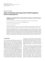
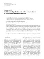
(a)Reconstructionfrombothdescriptions,D
0
= 28.52
(b) Reconstruction from Description 1, D
1
= 24.73
Figure 10: Sequence “Tempete,” frame 13.
the DCT. This property is common for most of 3D trans-
form video coders. We suppose that most of modern mo-
bile devices have enough memory to perform the encod-
ing.
Figure 10 shows frame 13 of the reference sequence Tem-
pete reconstructed from both descriptions (Figure 10(a))
and from Description 1 alone (Figure 10(b)). The sequence
is coded by 3D-2sMDC (Scheme 1) encoder to bitrate R
=
880 kbps. One can see that although the image reconstructed
from one description has some distortions caused by loss of
transform coefficient volumes of the residual sequence, the
overall pic ture is smooth and pleasant to the eye.
10 EURASIP Journal on Embedded Systems
8. CONCLUSION
We have proposed an MDC scheme for coding of video
which does not use motion-compensated prediction. The
coder exploits 3D transforms to remove correlation in video
sequence. The coding process is done in two stages: the first
stage produces coarse sequence approximation (shaper) try-
ing to fit as much information as possible in the limited
bit budget. The second stage encodes the residual sequence,
which is the difference between the original sequence and the
shaper-reconstructed one. The shap er is obtained by pruned
3D-DCT, and the residual signal is coded by 3D-DCT or hy-
brid 3D transform. The redundancy is introduced by includ-
ing the shaper in both descriptions. The amount of redun-
dancy is easily controlled by the shaper quantization step.
The scheme can also be easily optimized for suboptimal bit
allocation. This optimization can run in real time during the
encoding process.
The proposed MD v ideo coder has low computational
complexity, which makes it suitable for mobile devices with
low computational power and limited battery life. The coder
has been shown to outperform MDTC video coder and some
simple MD coders based on H.263+. The coder performs
especially well in a low-redundancy region. The encoder
is also less computationally expensive than the H.263 en-
coder.
ACKNOWLEDGMENT
This work is supported by the Academy of Finland, Project
no. 213462 (Finnish Centre of Excellence program (2006–
2011)).
REFERENCES
[1] R. K. Chan and M. C. Lee, “3D-DCT quantization as a com-
pression technique for video sequences,” in Proceedings of
the Annual International Conference on Virtual Systems and
Multimedia (VSMM ’97), pp. 188–196, Geneva, Switzerland,
September 1997.
[2] S. Saponara, L. Fanucci, and P. Terreni, “Low-power VLSI ar-
chitectures for 3D discrete cosine transform (DCT),” in Pro-
ceedings of the 46th IEEE International Midwest Symposium on
Circuits and Systems (MWSCAS ’03), vol. 3, pp. 1567–1570,
Cairo, Egypt, December 2003.
[3] A. Burg, R. Keller, J. Wassner, N. Felber, and W. Fichtner, “A
3D-DCT real-time video compression system for low com-
plexity sing le-chip VLSI implementation,” in Proceedings of
theMobileMultimediaConference(MoMuC’00), p. 1B-5-1,
Tokyo, Japan, November 2000.
[4] M. Bakr and A. E. Salama, “Implementation of 3D-DCT based
video encoder/decoder system,” in Proceedings of the 45th IEEE
Midwest Symposium on Circuits and Systems (MWSCAS ’02),
vol. 2, pp. 13–16, Tulsa, Okla, USA, August 2002.
[5] S. Boussakta and H. O. Alshibami, “Fast algorithm for the 3-D
DCT-II,” IEEE Transactions on Signal Processing, vol. 52, no. 4,
pp. 992–1001, 2004.
[6] ITU-T, Video coding for low bitrate communication. ITU-T
Recommendation, Draft on H.263v2, 1999.
[7] J. J. Koivusaari and J. H. Takala, “Simplified three-dimensional
discrete cosine transform based video codec,” in Multimedia
on Mobile Devices, vol. 5684 of Proceedings of SPIE, pp. 11–21,
San Jose, Calif, USA, January 2005.
[8] V. K. Goyal, “Multiple description coding: compression meets
the network,” IEEE Signal Processing Magazine, vol. 18, no. 5,
pp. 74–93, 2001.
[9] J. G. Apostolopoulos and S. J. Wee, “Unbalanced multiple de-
scription video communication using path diversity,” in Pro-
ceedings of IEEE International Conference on Image Processing
(ICIP ’01), vol. 1, pp. 966–969, Thessaloniki, Greece, October
2001.
[10] A. R. Reibman, H. Jafarkhani, Y. Wang, M. T. Orchard, and
R. Puri, “Multiple description coding for video using motion
compensated prediction,” in Proceedings of IEEE International
Conference on Image Processing (ICIP ’99), vol. 3, pp. 837–841,
Kobe, Japan, October 1999.
[11] J. G. Apostolopoulos, “Error-resilient video compression
through the use of multiple states,” in Proceedings of IEEE In-
ternational Conference on Image Processing (ICIP ’00), vol. 3,
pp. 352–355, Vancouver, BC, Canada, September 2000.
[12] V. Vaishampayan and S. A. John, “Balanced interframe mul-
tiple description video compression,” in Proceedings of IEEE
International Conference on Image Processing (ICIP ’99), vol. 3,
pp. 812–816, Kobe, Japan, October 1999.
[13] Y. Wang, A. R. Reibman, and S. Lin, “Multiple description cod-
ing for video delivery,” Proceedings of the IEEE, vol. 93, no. 1,
pp. 57–70, 2005.
[14]H.Man,R.L.deQueiroz,andM.J.T.Smith,“Three-
dimensional subband coding techniques for wireless video
communications,” IEEE Transactions on Circuits and Systems
for Video Technology, vol. 12, no. 6, pp. 386–397, 2002.
[15] J. Kim, R. M. Mersereau, and Y. Altunbasak, “Error-resilient
image and video transmission over the Internet using un-
equal error protection,” IEEE Transactions on Image Processing,
vol. 12, no. 2, pp. 121–131, 2003.
[16] S. Somasundaram and K. P. Subbalakshmi, “3-D multiple de-
scription video coding for packet switched networks,” in Pro-
ceedings of IEEE International Conference on Multimedia and
Expo (ICME ’03), vol. 1, pp. 589–592, Baltimore, Md, USA,
July 2003.
[17] M. Yu, Z. Wenqin, G. Jiang, and Z. Yin, “An approach to 3D
scalable multiple description video coding with content deliv-
ery networks,” in Proceedings of IEEE International Workshop
on VLSI Design and Video Technology (IWVDVT ’05)
, pp. 191–
194, Suzhou, China, May 2005.
[18] A. Norkin, A. Gotchev, K. Egiazarian, and J. Astola, “A low-
complexity multiple description video coder based on 3D-
transforms,” in Proceedings of the 14th European Signal Pro-
cessing Conference (EUSIPCO ’06), Florence, Italy, September
2006.
[19] A. Norkin, A. Gotchev, K. Egiazarian, and J. Astola, “Two-stage
multiple description image coders: analysis and comparative
study,” Signal Processing: Image Communication, vol. 21, no. 8,
pp. 609–625, 2006.
[20] A. M. Bruckstein, M. Elad, and R. Kimmel, “Down-scaling
for better transform compression,” IEEE Transactions on Im-
age Processing, vol. 12, no. 9, pp. 1132–1144, 2003.
[21] B L. Yeo and B. Liu, “Volume rendering of DCT-based com-
pressed 3D scalar data,” IEEE Transactions on Visualization and
Computer Graphics, vol. 1, no. 1, pp. 29–43, 1995.
Andrey Norkin et al. 11
[22] N. Bozinovic and J. Konrad, “Motion analysis in 3D DCT do-
main and its application to video coding,” Signal Processing:
Image Communication, vol. 20, no. 6, pp. 510–528, 2005.
[23] H. S. Malvar and D. H. Staelin, “The LOT: transform cod-
ing without blocking effects,” IEEE Transactions on Acoustics,
Speech, and Signal Processing, vol. 37, no. 4, pp. 553–559, 1989.
[24] W. H. R. Equitz and T. M. Cover, “Successive refinement of in-
formation,” IEEE Transactions on Information Theory, vol. 37,
no. 2, pp. 269–275, 1991.
[25] A. N. Skodras, “Fast discrete cosine transform pruning,” IEEE
Transactions on Signal Processing, vol. 42, no. 7, pp. 1833–1837,
1994.
[26] K. Rao and R. Yip, Discrete Cosine Transform: Algorithms, Ad-
vantages, Applications, Academic Press, London, UK, 1990.
[27] K. Yu, J. Lv, J. Li, and S. Li, “Practical real-time video codec for
mobile devices,” in Proceedings of IEEE International Confer-
ence on Multimedia and Expo (ICME ’03), vol. 3, pp. 509–512,
Baltimore, Md, USA, July 2003.
[28] G. Cote, B. Erol, M. Gallant, and F. Kossentini, “H.263+: video
coding at low bitrates,” IEEE Transactions on Circuits and Sys-
tems for Video Technology, vol. 8, no. 7, pp. 849–866, 1998.
[29] L. Roberts, “TMN 8 (h.263+) encoder/decoder, version 3.0,”
1997, Signal Processing and Multimedia Laboratory, Univiver-
sity of British Columbia, Vancouver, BC, Canada, May, 1997.
[30]S.D.Kim,J.Yi,H.M.Kim,andJ.B.Ra,“Adeblockingfil-
ter with two separate modes in block-based video coding,”
IEEE Transactions on Circuits and Systems for Video Technol-
ogy, vol. 9, no. 1, pp. 156–160, 1999.
[31] D. Rusanovskyy and K. Egiazarian, “Post-processing for three-
dimensional discrete cosine transform based video coding,”
in Proceedings of the 7th International Conference on Advanced
Concepts for Intelligent Vision Systems (ACIVS ’05), pp. 618–
625, Antwerp, Belgium, September 2005.
[32] V. Vaishampayan, “Design of multiple description scalar
quantizers,” IEEE Transactions on Information Theory, vol. 39,
no. 3, pp. 821–834, 1993.
[33] A. R. Reibman, H. Jafarkhani, Y. Wang, M. T. Orchard, and
R. Puri, “Multiple-description video coding using motion-
compensated temporal prediction,” IEEE Transactions on Cir-
cuits and Systems for Video Technology, vol. 12, no. 3, pp. 193–
204, 2002.