Báo cáo hóa học: " Research Article Collaborative Image Coding and Transmission over Wireless Sensor Networks" potx
Bạn đang xem bản rút gọn của tài liệu. Xem và tải ngay bản đầy đủ của tài liệu tại đây (1.06 MB, 9 trang )
Hindawi Publishing Corporation
EURASIP Journal on Advances in Signal Processing
Volume 2007, Article ID 70481, 9 pages
doi:10.1155/2007/70481
Research Article
Collaborative Image Coding and Transmission
over Wireless Sensor Networks
Min Wu
1
and Chang Wen Chen
2
1
MAKO Surgical Corporation, Fort Lauderdale, FL 33317, USA
2
Department of Electrical and Computer Engineering, Florida Institute of Technology (FIT), Melbourne FL32901, USA
Received 6 February 2006; Revised 3 August 2006; Accepted 13 August 2006
Recommended by Chun-Shien Lu
The imaging sensors are able to provide intuitive visual information for quick recognition and decision. However, imaging sensors
usually generate vast amount of data. Therefore, processing and coding of image data collected in a sensor network for the purpose
of energy efficient transmission poses a significant technical challenge. In particular, multiple sensors may be collecting similar
visual information simultaneously. We propose in this paper a novel collaborative image coding and transmission scheme to
minimize the energy for data transmission. First, we apply a shape matching method to coarsely register images to find out maximal
overlap to exploit the spatial correlation between images acquired from neighboring sensors. For a given image sequence, we
transmit background image only once. A lightweight and efficient background subtraction method is employed to detect targets.
Only the regions of target and their spatial locations are transmitted to the monitoring center. The whole image can then be
reconstructed by fusing the background and the target images as well as their spatial locations. Experimental results show that the
energy for image transmission can indeed be greatly reduced with collaborative image coding and transmission.
Copyright © 2007 M. Wu and C. W. Chen. This is an open access article distributed under the Creative Commons Attribution
License, which permits unrestricted use, distribution, and reproduction in any medium, provided the original work is properly
cited.
1. INTRODUCTION
Networked microsensor technology is becoming one of the
key technologies for the 21st century. Such sensor networks
are often designed to perform tasks such as detecting, classi-
fying, localizing, and tracking of one or more targets in the
sensor fields [1, 2]. Among all types of sensors, the imag-
ing sensors are able to provide intuitive visual information
for quick recognition and decision. However, imaging sen-
sors usually generate vast amount of image data. Therefore,
for battery-powered sensors, the transmission of image data
collected in a sensor network presents the most challenging
problem.
A number of research efforts are currently under way to
address the issues on collaborative signal and information
processing in distributed microsensor networks [3–6]. Prad-
han et al. proposed a distributed coding framework to realize
the coding gain of correlated data from Slepian-Wolf coding
theorem in information theory [3]. Ideally, no information
needs to be exchanged among correlated sensors during the
encoding process. At the decoder, data can be recovered by
reaping the full benefit of the correlation between neighbor-
ing sensor data. A very simple example is given to demon-
strate the feasibility of this coding framework. Many re-
searches are moving forward to distributed image and video
coding based on Wyner-Ziv theorem which is an extension to
lossy coding from Slepian-Wolf theorem [7–9]. Pradhan pro-
posed a syndrome-based multimedia coding [10]. Girod pre-
sented distributed video coding using turbo code [8]. How-
ever, the quality of reconstructed video is limited by the ac-
curacy of the prediction as side information from motion es-
timation at the decoding side. Girod also applied Wyner-Ziv
coding to distributed image compression for large camera ar-
rays [9]. To acquire a good estimate for the Wyner-Ziv coded
views, conventional cameras have to be interspersed among
sensor nodes.
Wagner et al. proposed another distributed image com-
pression scheme for sensor network [6] that is different
from the Slepian-Wolf and Wyner-Ziv coding. They use im-
age matching method to register correlated views to iden-
tify maximal overlap, and send the low-resolution over-
lapped areas to the receiver. At the receiver, super-resolution
recovery techniques are applied to reconstruct a high-
resolution version of the overlapped areas. In their work,
2 EURASIP Journal on Advances in Signal Processing
they only exploit spatial redundancy among the images. The
super-resolution overlap recovery requires multiple frames
of low-resolution overlap. Thus the imag ing sensors need
to be deployed very densely to accommodate such tech-
nique.
In this paper, we propose to build a collaborative im-
age coding and transmission system over distributed wire-
less sensor network. We consider exploiting both spatial
and temporal correlations among the sensor images to re-
duce overall energy consumption on data transmission and
processing. In our system, we assume that image sensors
transmit collected image data to the monitoring center via
multiple hops. Sensor nodes on the route to the moni-
toring center could access image data collected from pre-
vious hops. This assumption conforms to many energy-
efficient MAC protocols, such as data centric, hierarchical,
and location-based protocols [11].Sincesensornodehas
very limited processing power, image processing algorithm
perferably will be lightweighted and efficient and suitable
for these practical applications. To exploit the spatial corre-
lation between neighboring sensor images, a shape match-
ing method [12] is applied to find out maximal overlapped
areas. The shape matching algorithm is operated on a very
small number of the feature points, hence the computa-
tional complexity can be greatly reduced. A transformation
is then generated according to the matching result. We code
the original image and the difference between the reference
image and the transformed image. Then we transmit the
coded bit stream together with the transformation param-
eters.
In our intended application as surveillance, we assume
that the imaging sensors and their background scenes re-
main stationary over the entire image acquisition process. To
exploit the temporal correlation among images in the same
sensor, we transfer background image only once during any
triggered event and transmit images when one or more tar-
gets are detected. A simple background subtraction method
that is robust to global illumination change is applied to de-
tect targets. Whenever targets a re detected, only the regions
of targets and their spatial locations are transmitted to the
monitoring center. At the monitoring center, the whole im-
age can be reconstructed by fusing the background and the
target areas.
Since it has been proven that the power consumption for
data processing is much less than that for data communica-
tion, we expect that energy saving from reduced data com-
munication will significantly outweight the additional en-
ergy consumption from additional image matching and pro-
cessing. Experimental results show that the energy for image
transmission can indeed be greatly reduced with collabora-
tive image coding.
The rest of this paper is organized as follows. In Section 2,
we describe in detail our approach to the proposed collabo-
rative image coding and transmission over distributed wire-
less sensor networks. Experimental results are presented in
Section 3 to confirm the energy efficiency of the proposed ap-
proach. Section 4 concludes this paper with a summary and
some discussions.
Transmission route 2
Transmission route 1
Node 1
Node 2
Node 3
Node 4
Node 5
Node 6
Remote
header
Targe t
Camera direction
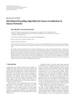
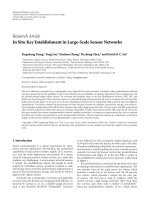
Figure 1: Diagram of sensor network.
2. THE PROPOSED APPROACH
2.1. Exploiting spatial correlation via image matching
In this work, we address the problem that imaging sensors
are relatively densely deployed for surveillance as shown in
Figure 1. Images in neighboring sensors are assumed spa-
tially correlated with typical overlaps as shown by the top
images in Figure 5. Transmitting the whole images indepen-
dently means that the image data received by the monitoring
center wil l have significant redundancy among images col-
lected from neighboring sensors. Data transmission in this
fashion will significantly shorten the sensor’s life time due to
unnecessary waste in the limited transmission power. This
makes local on-board data compression a more energy effi-
cient choice in low bandwidth lossy sensor networks [13]. We
can reduce the spatial redundancy between the neighboring
sensors so as to minimize the energy for transmission. No-
tice that we assume that sensor nodes communication is a
multi-hop fashion from sensor nodes to the monitoring cen-
ter. After one sensor sends its image to its neighboring sensor
along the route to the monitoring center, an image matching
method [12] can be applied to find out the maximal overlap
between the image acquired by the current sensor and the
image received from the previous hop. We adopt a computa-
tionally lightweight scheme to exploit the spatial correlation
between two neighboring images. This technique allows for
effective description of similar images in terms of only their
critical feature points via a shape descriptor known as shape
context. The shape context is a description of the coarse dis-
tribution of the gray scale in a neighboring area centered on
a given feature point. As this method uses a small set of im-
age feature points, it is preferrable for imaging sensors with
limited battery resource and computational capability.
The proposed image matching scheme is robust and
suitable for implementation in a energy constrained sensor
network. When an image is sent to a neighboring sensor,
the neighboring sensor computes registrations between the
transmitted image and the image taken by the neighboring
sensor. The transmitted image is referred to as original im-
age; the image taken by the neighboring sensor is referred
to as reference image. For simplicity, the dominant edges
on both images are extracted from the downsampled im-
ages. Any standard edge detection algorithm, such as Sobel
M. Wu and C. W. Chen 3
(a)
Angle
Log (r)
(b)
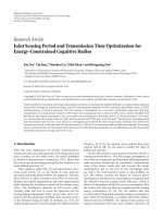
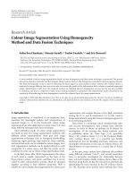
Figure 2: log-polar histogram bins and a shape context for one feature point.
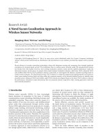
(a) (b)
Figure 3: Feature point sets extracted from two neigboring images.
operator, can be employed in this step. In the detection of
dominant edges, a threshold for edge detection algorithm is
selected so that only a presetted number of edge points are
detected for this threshold. The feature points are then ex-
tracted from the edge points such that the feature points are
evenly spaced along the edges. Then, in both feature point
sets, for each point a shape context is computed. The shape
context is a coarse histogr a m description oper ated on feature
point set [12]. The histogram is determined by the number
of feature points located in the bins shown in Figure 2(a). For
a feature point p
i
on the shape, the histogram h
i
is calculated
as
h
i
(k) = #
q = p
i
:
q − p
i
∈
bin(k)
,(1)
where q is feature point and k is the index of bins. The bins
are centered on the feature point and uniform in log-polar
space, making the descriptor more sensitive to positions of
nearby points than farther away points. Figure 2(b) shows a
shape context on one feature point in Figure 3. After two sets
of shape contexts are extracted from two correlated images, a
bipartite graph matching is employed to find the best one-to-
one match between two sets of points. The cost of matching
two points on two shapes is defined as
C
i, j
= C
p
i
, q
j
=
1
2
K
k=1
h
i
(k) − h
j
(k)
2
h
i
(k)+h
j
(k)
,(2)
where p
i
is a feature point in one image, and q
j
is a fea-
ture point in the other image. We minimize the total cost of
matching to find the best one-to-one match:
H
=
i, j
C
p
i
, q
j
. (3)
Once the correspondence of two shapes is obtained. The
correspondence of arbitrary pixels on two images is defined
as a plane transform that is defined as
f (x, y)
= a
1
+ a
x
x + a
y
y. (4)
4 EURASIP Journal on Advances in Signal Processing
From the finite set of correspondences between points on
two shapes, the coefficients of a are estimated by least mean
square solution:
Pa
= v,(5)
where f (x
i
, y
i
) = v
i
is corresponding locations when p
i
=
(x
i
, y
i
). a is a vector (a
1
, a
x
, a
y
). P is a matrix of coordinates
of the feature points:
P
=
⎛
⎜
⎝
1 x
1
y
1
:: :
1 x
n
y
n
⎞
⎟
⎠
. (6)
The regist rations allow us to identify the largest region
of overlap as described above. Once we get the coefficients a
through (5), we use two separate functions shown in (7)to
model a coordinate tr ansform to generate a warped image,
T(x, y)
=
f
x
(x, y), f
y
(x, y)
. (7)
The warped image has the best match with the reference
image, and this means that the two images have the maximal
overlap. We code the original image and the difference be-
tween the reference image and the warped image. Then we
transmit the coded bit stream together with the transforma-
tion parameters a to the next neighboring senor along the
route to the monitoring center. This will reduce the energy
on communication compared with transmitting two images
independently.
2.2. Exploiting temporal correlation via
background subtraction
In our research, we assume that the sensor network is in-
tended for surveillance. An event driven strategy can be
adopted for energy efficient deployment [14, 15]. In this case,
the sensors can be put into “sleep” state if no target has
been detected via nonimaging sensor [15, 16]. Once a tar-
get is detected by a nonimaging sensor, the imaging sensors
will wake up to work and the imaging sensor-based target
tracking stage will begin. We assume that the imaging sen-
sors and background scene remain relatively stationary dur-
ing the tracking stage. To further save energy consumption,
scene change detection can be implemented such that if the
scene does not change, sensor should not transmit image to
the monitoring center. When one or more targets are de-
tected, the imaging sensor will locate the target areas on the
image and transmit only the target areas together with their
spatial locations to the monitoring center. This will further
reduce the energy consumption on communication at the
cost of increasing signal processing energy on target detec-
tion. At the monitoring center, the image is reconstructed by
fusing the background and the target areas.
We adopt background subtraction method to detect tar-
get. This is a lightweight and efficient way for target detec-
tion. A number of background subtraction methods have
been proposed in recent years [17–20]. The basic idea of
background subtraction algorithm can be briefly described
as computing the color or intensities of pixels in the incom-
ing image and reference image. Significant differences in the
intensities from reference image were attributed to the tar-
gets. The intensity-based subtract ion is sensitive to the il-
lumination changes, because illumination changes increase
the deviation of the background pixels from the original
captured background images. Mittal and Huttenlocher pro-
posed a model to represent pixels in the scene [18]. They
constructed a background model to detect moving objects
in video sequences. Javed et al. proposed a hierarchical ap-
proach for robust background subtraction [17]. They also
used a statistical model to classify pixels whether belonging
to foreground or background.
As the imaging sensor has limited signal processing
power, lightweight and efficient target detection is desirable
in the application. To deal with the illumination changes, we
could update background at a short time interval to keep the
illumination changes under a fixed threshold. However, this
will increase the burden of image transmission. Another so-
lution is employing background subtraction in gradient im-
age. The basic idea is that any foreground region that corre-
sponds to an actual object will have high values of gradient-
basedbackgrounddifference at its boundaries; any slow il-
lumination changes could be eliminated in gradient image.
The g radients are calculated from the gray level image. Let
I be the current image and Δ be the gradient feature vector
of its gray levels. We use Δ
=
Δ
m
, Δ
d
as a feature vector
for gradient-based background differencing, where Δ
m
is the
gradient magnitude, that is,
d
2
x
+ d
2
y
and Δ
d
is the gradient
direction, that is, tan
−1
(d
y
/d
x
). For any region R
a
that corre-
sponds to some foreground objects in the scene, there will be
a high gradient at ∂R
a
on the image I,where∂R
a
is the set
of boundary pixels (i, j)ofregionR
a
. Thus it is reasonable
to assume that Δ will have high deviation from the gradient
background model at the boundar y pixels. For each newly
captured image, gradient magnitude and the direction values
are computed. If for a certain gradient vector, the difference
from the background gradient vector is greater than a prese-
lected threshold, the pixel belongs to foreground, otherwise,
it belongs to background.
We should point out that there are two types of errors
in the target detection step. The first type is missing target.
In this case, there is a target in the image, but the system is
unable to detect it. The second type is erroneous target de-
tection. In this case, the system detects a “target” that is not
a true target. In background subtraction, most detection er-
rors are the second type of errors. When such a detection er-
ror occurs in the process, the sensor transmits a freak target
to the monitoring center. At the monitoring center, this type
of error will not influence the monitoring and surveillance
task since it can be easily recognized as a detection error. The
freak target may be due to the variation of background scene
or abrupt illumination change.
2.3. Collaborative image coding
In this system, we assume that each sensor has a processor
to acquire images and perform background subtraction, and
M. Wu and C. W. Chen 5
feature-based image matching. Both spatial and temporal
correlations have been exploited, and three types of images
are generated: whole original image, difference image, and
small scale target area image. The goal of the collaborative
image coding is to reduce the transmission power consump-
tion of this imaging sensor network.
Images are distributedly compressed in an efficient and
timely manner. There are many choices to compress all three
types of images. The state-of-the-art coding methods include
SPIHT, JPEG2000, and H.264 intra-mode. Since wireless
channels are highly error pone in sensor network, and sen-
sor images are captured in very low frequency, fully scalable
image coding is very desirable in the sensor network appli-
cation. H.264 intra-mode has high coding efficient and low
complexity by using integer transform and intra-prediction
mode. However, it does not provide progressive coding that is
desirable for error prone channel in sensor network. SPIHT
provides high coding efficiency in a fully progressive fash-
ion: images can be reconstructed with any length of received
encoded bit stream. We use SPIHT algorithm to compress
all three types of images: whole image, difference image, and
small scale target area image.
At the monitoring center, the original image and the dif-
ference between the reference image and the warped im-
age are first decoded. Transforming original image using
transformation parameters generates the warped image. The
warped image plus the difference from the reference image
will generate the image from the neighboring sensor. The re-
constructed target image will fuse with the background im-
age to generate the image for the purpose of surveillance.
2.4. Collaborative image transmission
Consider the sensor network shown in Figure 1, the goal for
collaborative image transmission is to reduce the transmis-
sion energy, or equivalently, reducing the total data amount,
while maintaining adequate quality of the reconstruction
from all image sensors within the cluster. At the beginning,
each sensor tr ansmits its background scene only once to the
monitoring center. The gradient vectors are also computed
on background image and saved as the reference. Each sensor
takes pictures at a fixed interval. The background subtraction
method described above is employed on each captured im-
age. Whenever one or more targets are detected, the target
areas and their spatial locations are t ransmitted to the mon-
itoring center. At the monitoring center, the receiver is able
to reconstruct the whole image by fusing the background
data with target image as well as its spatial locations infor-
mation. The procedure of collaborative image transmission
in Figure 1 can be summarized as follows.
(1) Transmission operations.
(a) Transmit the background of the target along the
route of sensor 1, sensor 2, sensor 3, and remote
sensor and another route of sensor 4, sensor 5,
sensor 6, and remote sensor, respectively.
(b) At sensors 2, 3, 5, and 6 apply the algorithm
in Section 2.1 to remove spatial redundancy be-
NN-1 N-2 3 2 1
(a)
NN-1 N/2 + 1 N/2 2 1
(b)
Figure 4: Two routing schemes.
tween images in sensors 1 and 2, sensors 2 and 3,
sensors 4 and 5, and sensors 5 and 6, respectively.
(c) At each sensor, whenever a target is detected by
applying the algorithm in Section 2.2 on a new
captured image, the extracted target area and its
spatial location are transmitted to the remote
sensor along the same route.
(2) Reconstruction operations at the monitoring center.
(a) Restore the backg round image transmitted from
each sensor.
(b) Reconstruct sensor images by fusing background
and target area as well as its spatial location each
time after target image and its spatial location are
received.
In summary, only one full background image needs to be
transmitted from each sensor. Whenever targets are detected,
only target area and its spatial location need to be transmitted
to the monitoring center. At the monitoring center, the whole
image can be reconstructed by the fusion of the background
data and the target as well as its spatial location.
Since a distributed sensor network has multiple paths
from the source to the destination, different routings may
result in different network performance, such as delay and
network life. Figure 4 shows two simple routing schemes.
Suppose that in both schemes each sensor captures one im-
age a nd transmits to the monitoring center. We denote ith
original image with I
i
, the difference between image i and
the wrapped image i
− 1withD
i,i−1
, image matching be-
tween image i and image i
− 1withM
i,i−1
.InFigure 4(a),
6 EURASIP Journal on Advances in Signal Processing
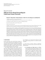
(a) (b)
(c)
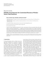
Figure 5: Two neighboring images and their warping difference.
sensor 1 encodes I
1
, and transmits to sensor 2, sensor 2
decodes I
1
, performs image matching M
2,1
,andencodes
D
2,1
. Sensor N decodes I
1
, D
2,1
, D
3,2
, , D
N−1,N−2
,performs
image matching M
N,N−1
,encodesD
N,N−1
, and transmits
I
1
, D
2,1
, D
3,2
, , D
N,N−1
. Figure 4(b) shows another scheme,
image 1 and N reach monitoring center via N/2 hops. For
simplicity, we ignore the subscripts in calculating the total
number of operations in image processing and transmission.
With collaborative image processing, in total Figure 4(a) en-
codes I+(N
−1)×D,decodes(N −1)×I+(N−1)(N−2)/2×D,
performs (N
−1)×M, and transmits N ×I +N(N −1)/2×D.
Figure 4(b) encodes 2
×I +(N −2)×D,decodes(N −2)×I +
(N
− 2)(N − 4)/4 × D,performs(N − 2) × M, and transmits
N
× I +(N +1)(N − 1)/4 × D.
Without collaborative image processing, Figure 4(a) en-
codes N
× I and transmits (N +1)N/2 × I; Figure 4(b) en-
codes N
× I and transmits (N +2)N/4 × I. The evaluation of
energy consumption will be addressed in next section. With
collaborative image processing, apparently, Figure 4(b) has
less image operations and fewer bits in transmission. Also
in Figure 4(a) sensor N consumes much more energy than
that of sensor 1, this unbalance in energy drain will reduce
the overall network lifetime. This analysis helps to choose the
topology of sensor network and routing. The total number of
hops will be as smal l as possible.
3. EXPERIMENTAL RESULTS
The experiment is conducted on the imaging sensors de-
ployed as shown in Figure 1. The average distance between
the neighboring sensors is 10 meters. The size of each im-
age taken by imaging sensor is 384
× 288. Intel StrongARM
SA 1110 and National Semiconductor LMX 3162 are used as
processor and transceiver, respectively, in sensor node. LMX
3162 works in 2.4 GHz unlicensed band. The transmission
power is 80 mJ when sending data. The tr ansmission rate
is 1 Mbps. We only consider the application layer in sensor
communication. Two sensor transmission routes are shown
in Figure 1. One route is from sensor 1, sensor 2, sensor 3, to
the remote sensor. The other route is from sensor 4, sensor
5, sensor 6, to the remote sensor. Each sensor is deployed to
monitor traffic condition on a road.
3.1. Image matching to exploit spatial correlation
Two views of a scene taken from different sensors are shown
as in the top two images in Figure 5.Fortyfivefeature
points are extracted from the dominant edges on two images.
Figure 3 shows feature points extracted from the top two im-
ages in Figure 5. Figure 5(a) is used as original image, and
Figure 5(b) is used as reference image. After bipartite graph
M. Wu and C. W. Chen 7
(a) (b)
(c) (d)
Figure 6: Result of background subtraction.
matching, we obtain best one-to-one pair match of the two
sets of feature points. Following the shape context registra-
tion process, we obtain transform parameters a from (5). A
warped image is generated by transforming Figure 5(a). The
difference image of the warped image and the reference im-
age is shown in Figure 5(c). The maximal overlap is identi-
fied and the coding cost is reduced. Then we only transmit
the original image and the difference image together with the
warping transform parameters to the monitoring centering
to reduce energy on transmission.
3.2. Background subtraction to exploit
temporal correlation
The top two images in Figure 6 are taken by the same sen-
sor. Figure 6(a) is the background that is to be transmitted
to the monitoring center. When a new image is captured
in the same sensor, the background subtraction algorithm
described in Section 2.2 is employed for target detection.
Figure 6(b) is captured with a target, a car, on it. Figure 6(c)
is the result of the background subtraction. The car is suc-
cessfully detected. At the same time, some small areas of the
tree movement are also detected. Those areas can be viewed
as noise and will be eliminated by a size filter. The detected
areas with small size are considered as noises. Figure 6(d)
shows the result after applying size filter. Only the car is left
on this image. The sensor then transmits only a rectangle
block containing this target area to the monitoring center.
3.3. Energy saving in collaborative
image transmission
The energy saving on background subtraction is dependent
on the size of the targets and how often the targets are de-
tected. The energy saving on the image matching is depen-
dent on the ratio of overlaps. In this experiment, we con-
sider the case that each sensor transmits its background a nd
the detected target area shown in Figure 6 to the monitor-
ing center. In this case, the target is in the area of 48
× 36,
which is 1/64 of the entire image. When calculating the total
energy consumption in additional image processing intro-
duced in this collaborative image transmission, we adopt the
unit energy consumptions of an m-bits addition and multi-
plication operation as E
add
= 3.3 × 10
−5
mmW/MHz and
E
mult
= 3.7 × 10
−5
m
3
mW/MHz, assuming that SA 1110
works on 206 MHz. Table 1 shows the energy consumption
on transmission, processing on image registration, as well
as the additional processing in background subtraction. The
8 EURASIP Journal on Advances in Signal Processing
Table 1: Energy consumption comparison with and without the
proposed collaborative image t ransmission scheme.
W collaboration W/O collaboration
Energy on image
0.577 1.7
transmission (J)
Additional energy for
0.222 —
image registration
Additional energy for
0.006 —
background subtraction
Total energy consumption 0.805 1.7
Energy saving 53% —
saving in transmission energy due to reduced data transmis-
sion is about 1.1 J, while the additional energy consumption
due to the increase in collaborative processing is about 0.23 J.
Taking both types of energy consumption into consideration,
we find that the total energy can be saved 53% by the pro-
posed collaborative image transmission scheme.
4. SUMMARY AND DISCUSSION
In this paper, we described a novel collaborative image trans-
mission scheme for wireless sensor networks. In our applica-
tion, we consider exploiting both spatial and temporal cor-
relations to save overall energy consumption on data trans-
mission and processing. To exploit the spatial correlation be-
tween images in neighboring imaging sensors, after one im-
age is transmitted to its neighboring imaging sensor along
the route, we employ the image matching method involv-
ing image feature points to roughly register images in order
to find out the maximal overlap. Then, we warp the orig-
inal image and code the original image and the difference
between the reference and the warped image. This will sig-
nificantly reduce transmission energy comparing with trans-
mitting two individual images independently. To exploit the
temporal correlation between images in each sensor, we em-
ploy background subtraction algorithm on gradient image to
detect target. We only transmit background image from each
sensor to the monitoring center once. Whenever one or more
targets are detected, only the regions of targets and their spa-
tial locations are transmitted to the monitoring center. At the
monitoring center, the whole image can b e reconstructed by
fusing the background and the target image as well as its spa-
tial location. Experimental results show that the transmission
energycanbegreatlyreduced.Fortheexamplewepresented
in this paper, the total energy, including both processing en-
ergy and transmission energy, has been saved 53%.
This is the first attempt to apply collaborative signal
processing principles to imaging sensor networks. The vast
amount of image data these sensors collect and the intrin-
sic characteristics of these images pose significant challenge
in how to efficiently compress and transport the sensor
data wirelessly via multi-hop routing to a monitoring cen-
ter with an acceptable quality-of-service guarantee. Because
such a sensor network is usually severely constrained by
battery power and processing capability, there are potential
trade-offs that need to be carefully studied so that the over-
all system energy consumption can be minimized while still
maintaining an acceptable image quality, for instant, recog-
nition and decision at the remote monitoring center to carry
out its surveillance tasks.
We would like to point out that the proposed scheme is
designed for the application that neighbouring sensor images
have high correspondance. Current typical scenario for such
application can often be found in the outdoor environment.
Therefore, we considered lighting changes in the outdoor en-
vironment during the day and proposed periodic update of
background reference images. When the proposed algorithm
is applied to indoor applications, additional attention on per-
spective distort ion is needed to ensure that the correlation of
the background remains sufficiently high to adopt the pro-
posed scheme. With the increase of the processing power of
sensor nodes, we will develop more complex algorithm to
deal with the complicated cases in which the imaged scene
presents foreground and background objects so as to avoid
the possibility to compensate one image w ith respect to an-
other with the transformation defined in (7).
ACKNOWLEDGMENT
This research is supported by FIT Allen Henry Endowment
Fund.
REFERENCES
[1] D. Estrin, L. Girod, G. Pottie, and M. Srivastava, “Instrument-
ing the world with wireless sensor networks,” in Proceedings of
IEEE International Conference on Acoustics, Speech and Signal
Processing (ICASSP ’01), vol. 4, pp. 2033–2036, Salt Lake City,
Utah, USA, May 2001.
[2] C. Savarese, J. M. Rabaey, and J. Beutel, “Locationing in dis-
tributed ad-hoc wireless sensor networks,” in Proceedings of
IEEE International Conference on Acoustics, Speech and Signal
Processing (ICASSP ’01), vol. 4, pp. 2037–2040, Salt Lake City,
Utah, USA, May 2001.
[3] S. S. Pradhan, J. Kusuma, and K. Ramchandr an, “Distr ibuted
compression in a dense microsensor network,” IEEE Signal
Processing Magazine, vol. 19, no. 2, pp. 51–60, 2002.
[4] D. Li, K. D. Wong, Y. H. Hu, and A. M. Sayeed, “Detection,
classification, and tracking of targets,” IEEE Signal Processing
Magazine, vol. 19, no. 2, pp. 17–29, 2002.
[5] Y. J. Zhao, R. Govindan, and D. Estrin, “Residual energy scan
for monitoring sensor networks,” in Proceedings of IEEE Wire-
less Communications and Networking Conference (WCNC ’02),
vol. 1, pp. 356–362, Orlando, Fla, USA, March 2002.
[6] R. Wagner, R. Nowak, and R. Baraniuk, “Distributed image
compression for sensor networks using correspondence anal-
ysis and super-resolution,” in Proceedings of IEEE Internat ional
Conference on Image Processing (ICIP ’03), vol. 1, pp. 597–600,
Barcelona, Spain, September 2003.
[7] A. D. Liveris, Z. Xiong, and C. N. Georghiades, “A distributed
source coding technique for correlated images using turbo-
codes,” IEEE Communications Letters, vol. 6, no. 9, pp. 379–
381, 2002.
M. Wu and C. W. Chen 9
[8] B. Girod, A. Aaron, S. Rane, and D. Rebollo-Monedero, “Dis-
tributed video coding,” Proceedings of the IEEE,vol.93,no.1,
pp. 71–83, 2005, IEEE special issues on advances in video cod-
ing and delivery, 2004.
[9] X. Z hu, A. Aaron, and B. Girod, “Distributed compression for
largecameraarrays,”inProceedings of IEEE Workshop on Sta-
tistical Signal Processing (SSP ’03), pp. 30–33, St. Louis, Mo,
USA, September-October 2003.
[10] R. Puri and K. Ramchandran, “PRISM: a video coding
architecture based on distributed compression principles,”
Tech. Rep. UCB/ERL M03/6, EECS Department, University
of California, Berkeley, Calif, USA, 2003, s.
berkeley.edu/ kannanr/PRISM/.
[11] K. Akkaya and M. Younis, “A survey on routing protocols for
wireless sensor networks,” Ad Hoc Networks, vol. 3, no. 3, pp.
325–349, 2005.
[12] S. Belongie, J. Malik, and J. Puzicha, “Shape matching and ob-
ject recognition using shape contexts,” IEEE Transactions on
Pattern Analysis and Machine Intelligence, vol. 24, no. 4, pp.
509–522, 2002.
[13] R. Bhargava, H. Kargupta, and M. Powers, “Energy consump-
tion in data analysis for on-board and distributed applica-
tions,” in Proceedings of the ICML Workshop on Machine Learn-
ing Technologies for Autonomous Space Applications, Washing-
ton, DC, USA, August 2003.
[14] K. Akkaya and M. Younis, “An energy-aware QoS routing
protocolforwirelesssensornetworks,”inProceedings of the
23rd International Conference on Distributed Computing Sys-
tems Workshops (ICDCSW ’03), pp. 710–715, Providence, RI,
USA, May 2003.
[15] A. Mainwaring, J. Polastre, R. Szewczyk, D. Culler, and J. An-
derson, “Wireless sensor networks for habitat monitoring,”
in Proceedings of the ACM International Workshop on Wireless
Sensor Networks and Applications (WSNA ’02), pp. 88–97, At-
lanta, Ga, USA, September 2002.
[16] W. Ye, J. Heidemann, and D. Estrin, “An energy-efficient MAC
protocolforwirelesssensornetworks,”inProceedings of the
21st Annual Joint Conference of the IEEE Computer and Com-
munications Societies (INFOCOM ’02), vol. 3, pp. 1567–1576,
New York, NY, USA, June 2002.
[17] O. Javed, K. Shafique, and M. Shah, “A hierarchical approach
to robust background subtraction using color and gradient in-
formation,” in Proceedings of IEEE Workshop on Motion and
Video Computing (MOTION ’02), pp. 22–28, Orlando, Fla,
USA, December 2002.
[18] A. Mittal and D. Huttenlocher, “Scene modeling for wide area
surveillance and image synthesis,” in Proceedings of IEEE Con-
ference on Computer Vision and Pattern Recognition (CVPR
’00), vol. 2, pp. 160–167, Hilton Head Island, SC, USA, June
2000.
[19] A. Monnet, A. Mittal, N. Paragios, and V. Ramesh, “Back-
ground modeling and subt raction of dynamic scenes,” in Pro-
ceedings of IEEE Conference on Computer Vision and Pattern
Recognition (CVPR ’00), Hilton Head Island, SC, USA, June
2000.
[20] Y. Ivanov, A. Bobick, and J. Liu, “Fast lighting independent
background subtraction,” International Journal of Computer
Vision, vol. 37, no. 2, pp. 199–207, 2000.
Min Wu received his B.S. degree from Ts-
inghua University in 1993, M.S. degree from
University of Science and Technology of
China, in 1997, and Ph.D. degree from De-
partment of Electrical and Computer En-
gineering, University of Missouri-Columbia
in 2005. He served as Lecturer with the De-
partment of Automation, University of Sci-
ence and Technology of China, from 1997
to 2000. In 2005, he joined MAKO Surgical
Corp. at Fort Lauderdale, FL, as senior software engineer. His cur-
rent research interests are focused on biomedical image processing,
wireless image/video transmission, and wireless sensor network.
He is a member of Sigma Xi and IEEE, and was named one of the
three finalists for 2003 Association for the Advancement of Medical
Instrumentation (AAMI) Young Investigator Competition.
Chang Wen Chen received the B.S. degree
from University of Science and Technology
of China in 1983, M.S.E.E. degree from Uni-
versity of Southern California, Los Angeles,
in 1986, and Ph.D. degree from University
of Illinois at Urbana-Champaign, in 1992.
He has been Allen S. Henry Distinguished
Professor in the Department of Electrical
and Computer Engineering at the Florida
Institute of Technology since July 2003. Pre-
viously, he was on the faculty at the University of Missouri-
Columbia and at the University of Rochester. From 2000 to 2002, he
served as the Head of Interactive Media Group at the David Sarnoff
Research Laboratories in Princeton, NJ. He has received a number
of awards including the Sigma Xi Excellence in Graduate Research
Mentoring Award in 2003. He was elected an IEEE Fellow in 2004.
He has been the Editor-in-Chief for IEEE trans. Circuits and Systems
for Video Technology (T-CSVT) since January 2006. He has been
an Editor for a number of journals, including Proceedings of IEEE,
IEEE trans. Multimedia, IEEE T-CSVT, IEEE Multimedia, Journal of
Visual Communication and Image Representation. He served as the
the Chair of the Technical Program Committee for ICME 2006 held
in Toronto, Canada in July 2006.