Báo cáo hóa học: " Software-Defined Radio—Basics and Evolution to Cognitive Radio" pptx
Bạn đang xem bản rút gọn của tài liệu. Xem và tải ngay bản đầy đủ của tài liệu tại đây (621.08 KB, 9 trang )
EURASIP Journal on Wireless Communications and Networking 2005:3, 275–283
c
2005 Friedrich K. Jondral
Software-Defined Radio—Basics and Evolution
to Cognitive Radio
Friedrich K. Jondral
Universit
¨
at Karlsruhe (TH), Institut f
¨
ur Nachrichtentechnik, D-76128 Karlsruhe, Germany
Email:
Received 24 February 2005; Revised 4 April 2005
We provide a brief overview over the development of software-defined or reconfigurable radio systems. The need for software-
defined radios is underlined and the most important notions used for such reconfigurable transceivers are thoroughly defined.
The role of standards in radio development is emphasized and the usage of transmission mode parameters in the construction
of software-defined radios is described. The software communications architecture is introduced as an example for a framework
that allows an object-oriented development of software-defined radios. Cognitive radios are introduced as the next step in radio
systems’ evolution. The need for cognitive radios is exemplified by a comparison of present and advanced spectrum management
strategies.
Keywords and phrases: software-defined radio, reconfigurable transceiver, mobile communication standards, cognitive radio,
advanced spectrum management.
1. INTRODUCTION
Reconfigurability in radio development is not such a new
technique as one might think. Already during the 1980s re-
configurable receivers were developed for radio intelligence
in the short wave range. These receivers included interesting
features like automatic recognition of the modulation mode
of a received signal or bit stream analysis. Reconfigurability
became familiar to many radio developers with the publica-
tion of the special issue on software radios of the IEEE Com-
munication Magazine in April 1995.
Werefertoatransceiverasasoftware radio (SR) if its
communication functions are realized as programs running
on a suitable processor. Based on the same hardware, differ-
ent transmitter/receiver algorithms, which usually describe
transmission standards, are implemented in software. An SR
transceiver comprises all the layers of a communication sys-
tem. The discussion in this paper, however, mainly concerns
the physical layer (PHY).
The baseband signal processing of a digital radio (DR) is
invariably implemented on a digital processor. An ideal SR
directly samples the antenna output. A software-defined ra-
dio (SDR) is a practical version of an SR: the received signals
are sampled after a suitable band selec tion filter. One remark
This is an open access article distributed under the Creative Commons
Attribution License, which permits unrestricted use, distribution, and
reproduction in any medium, provided the original work is properly cited.
concerning the relation between SRs and SDRs is necessary at
this point: it is often argued that an SDR is a presently realiz-
able version of an SR since state-of-the-art analog-to-digital
(A/D) converters that can be employed in SRs are not avail-
able today. This argument, although it is correct, may lead to
the completely wrong conclusion that an SR which directly
digitizes the antenna output should be a major goal of future
developments. Fact is that the digitization of an unnecessary
huge bandwidth filled with many different signals of which
only a small part is determined for reception is neither tech-
nologically nor commercially desirable.
1
However, there is no
reason for a receiver to extremely o versample the desired sig-
nals while respecting extraordinary dynamic range require-
ments for the undesired in-band signals at the same time.
Furthermore, the largest portion of the generated digital in-
formation, which stems from all undesired in-band signals,
is filtered out in the first digital signal processing step.
A cognitive radio (CR) is an SDR that additionally senses
its environment, tracks changes, and reacts upon its findings.
A CR is an autonomous unit in a communications environ-
ment that frequently exchanges information with the net-
works it is able to access as well as with other CRs. From our
point of view, a CR is a refined SDR while this again repre-
sents a refined DR.
1
This is not an argument against the employment of multichannel or
wideband receivers.
276 EURASIP Journal on Wireless Communications and Networking
ReceiveTran s mit
Radio
frequency
(RF)
Analog-to-digital
conversion
(A/D)
Baseband
processing
Data
processing
Control
(parameterization)
Radio front end
To u s e r
From user
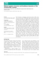
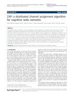
Figure 1: SDR transceiver.
According to its operational area an SDR can be
(i) a multiband system which is supporting more than one
frequency band used by a wireless standard (e.g., GSM
900, GSM 1800, GSM 1900),
(ii) a multistandard system that is supporting more than
one standard. Multistandard systems can work within
one standard family (e.g., UTRA-FDD, UTRA-TDD
for UMTS) or across different networks (e.g., DECT,
GSM, UMTS, WLAN),
(iii) a multiservice system which provides different services
(e.g., telephony, data, video streaming),
(iv) a multichannel system that supports two or more in-
dependent transmission and reception channels at the
same time.
Our present discussion is on multimode systems which are
combinations of multiband and multistandard systems.
The SDR approach allows different levels of reconfigura-
tion within a t ransceiver.
(i) Commissioning: the configuration of the system is
done once at the time of product shipping, when the
costumer has asked for a dedicated mode (standard or
band). This is not a true reconfiguration.
(ii) Reconfiguration with downtime: reconfiguration is only
done a few times during product lifetime, for example,
when the network infrastructure changes. The recon-
figuration will take some time, where the transceiver is
switched off. This may include the exchange of com-
ponents.
(iii) Reconfiguration on a per call basis: reconfiguration is
a highly dynamic process that works on a per call de-
cision. That means no downtime is acceptable. Only
parts of the whole system (e.g., front-end, digital base-
band processing) can be rebooted.
(iv) Reconfiguration per timeslot: reconfiguration can even
be done during a call.
Figure 1 shows an SDR transceiver that differs from a
conventional transceiver only by the fact that it can be recon-
figured via a control bus supplying the processing units with
the parameters which describe the desired standard. Such
a configuration, called a parameter-controlled (PaC) SDR,
guarantees that the transmission can be changed instanta-
neously if necessary (e.g., for interstandard handover).
The rest of this paper is org a nized as follows. In Section 2
we take a look at the most important wireless transmis-
sion standards currently used in Europe and specify their
main parameters. Section 3 provides an overview of design
approaches for mobile SDR terminals, especially over PaC-
SDRs. In Section 4 the software communications architec-
ture (SCA), as it is used in the US Joint Tactical Radio System
(JTRS), is introduced. The notion of cognitive radio (CR)
is discussed in Section 5 and the need for a modified spec-
trum management in at least some major portions of the
electromagnetic spectrum is underlined in Section 6. Finally,
in Section 7 we propose the development of technology cen-
tric CRs as a first step towards terminals that may sense their
environment a nd react upon their findings. Conclusions are
drawn in Section 8.
2. MOBILE COMMUNICATION STANDARDS
Standards are used to publicly establish transmission meth-
ods that serve specific applications employable for mass mar-
kets. The presently most important mobile communication
standards used in Europe are briefly described in the follow-
ing paragraphs.
Personal area networks
Bluetooth is a short distance network connecting por table
devices, for example, it enables links between computers,
mobile phones or connectivity to the internet.
Cordless phone
DECT (digital enhanced cordless telecommunications) pro-
vides a cordless connection of handsets to the fixed telephone
system for in-house applications. Its channel access mode is
FDMA/TDMA and it uses TDD. The modulation mode of
DECT is Gaussian minimum shift keying (GMSK) with a
bandwidth (B) time (T) product of BT
= 0.5. The transmis-
sion is protected only by a cyclic redundancy check (CRC).
Wireless local area networks
Today, IEEE 802.11b instal lations are the most widely used
in Europe. Also, IEEE 802.11a systems are in operation. If
IEEE.11a is to be implemented into an SDR, it should be
recognized that its modulation mode is OFDM. It should
be pointed out here that there are major efforts towards the
development of joint UMTS/WLAN systems which use the
SDR approach.
Cellular systems
GSM (global system for mobile communication) is presently
the most successful mobile communication standard world-
wide. Channel access is done via FDMA/TDMA and GSM
uses FDD/TDD. The modulation mode of GSM is GMSK
with a bandwidth time product of BT
= 0.3. Error correction
coding is done by applying CRC as well as a convolutional
code. GSM was originally planned to be a voice communi-
cation system, but with its enhancements HSCSD, GPRS, or
EDGE, it served more and more as a data system, too. In Eu-
rope, GSM systems are operating in the 900 MHz (GSM 900)
SDR—Basics and Evolution to Cognitive Radio 277
800 900 1000 1100 1200 1300 1400 1500 1600
890
915
935
960
1600 1700 1800 1900 2000 2100 2200 2300 2400 2500
1710
1785
1805
1880
1920
1980
2010
2025
2110
2170
2483.5
5100 5200 5300 5400 5500 5600 5700 5800 5900
5150
5350
5470
5725
GSM
DECT
UTRA-TDD
UTRA-FDD
MSS
ISM
WLAN
f (MHz)···
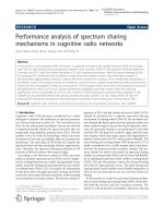
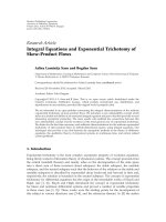
Figure 2: Mobile spectr um in Europe.
as well as in the 1800 MHz (GSM 1800) bands. The North
American equivalent of GSM is IS-136. Also, GSM 1900 as
well as IS-95, a second-generation CDMA system, are widely
used in the US. UMTS (universal mobile telecommunication
system) is the European version of the third-generation fam-
ily of standards within IMT-2000. One of the differences with
respect to second-generation systems is that third-generation
systems are mainly developed for data (multimedia) trans-
mission. UMTS applies two air interfaces: UTRA-FDD and
UTRA-TDD according to the duplex modes used. The chan-
nel access mode is CDMA. CRC, convolutional codes, as well
as turb o codes [1] are employed for error protection. The
basic data modulation is QPSK. Furthermore, it should be
mentioned that one mobile user within an UTRA-FDD cell
can occupy up to seven channels (one control and six trans-
port channels) simultaneously.
Figure 2 gives an overview o ver the present spectrum al-
location for mobile communications in Europe. Besides the
spectra of the standards mentioned above, also the spectra
allocated to mobile satellite system (MSS) as well as to indus-
trial, scientific, and medical (ISM) applications are specified.
The arrows within some of the bands indicate whether uplink
(mobile to base station) or downlink (base station to mobile)
trafficissupported.
In connection with mobile communications, some addi-
tional groups of standards have to be discussed.
Professional mobile radio
PMR standards are developed for police, firefighters, and
other administrative applications. The main difference to cel-
lular systems is that they allow direct handheld to hand-
held communication. The main PMR systems in Europe are
TETRA (recommended by ETSI) and TETRAPOL.
Location and navigation
One important feature of mobile terminals is their ability to
determine their own location as well as to track location in-
formation. Today many location-dependent services rely on
the global positioning system (GPS). Currently the European
satellite location and navigation system Galileo is u nder de-
velopment.
Digital broadcast
There is a possibility that digital broadcast systems may be
used as downstreaming media within future mobile commu-
nication infrastructures. The main developments in Europe
in this area are digital audio broadcast (DAB) and digital
video broadcast (DVB).
To have a sound basis for the description of a PaC-SDR
that can be switched between different standards, the most
important parameters of selected air interfaces are summa-
rized in Table 1.
3. MOBILE SDR TERMINALS
The general structure of a PaC-SDR terminal was already
given in Figure 1. Now we are going to look into the PaC-SDR
transceiver structure in a more detailed way. The main pro-
cessing modules of an SDR terminal a re the radio front-end,
the baseband processing, and the data processing. Since a lot
of information about baseband processing can be found in
the literature [2, 3] and since data processing is out of the
scope of this paper, we are going to focus on the front-end
here.
The receiver branch tr ansforms the analog RF antenna
signal into its digital complex baseband representation.
278 EURASIP Journal on Wireless Communications and Networking
Table 1: Parameters of selected air interfaces.
Bluetooth DECT GSM UTRA-FDD
Frequency range 2.4 GHz (ISM band) 1900 MHz 900, 1800, 1900 MHz 2 GHz
Channel bandwidth 1 MHz 1728 kHz 200 kHz 5 MHz
Access mode
TDMA
FDMA/TDMA FDMA/TDMA
Direct sequence (DS)
CDMA
Duplex mode TDD TDD FDD FDD
Users per carrier frequency 8 maximum 12 8 —
Modulation
FH sync. to master station,
GMSK GMSK
QPSK
GFSK with modulation
index between 0.28 and 0.35
Error correction code — No (CRC) CRC, convolutional CRC, convolutional, turbo
Bit (chip) rate 1 Mbps 1152 kbps 270.833 kbps 3.840 Mchip/s
Number of bits (chips)/burst
(slot)
625
480 (DECT P32)
156.25
2560
Frame duration — 10 ms 4.615 ms 10 ms
Number of bursts
(slots)/frame
—
24
815
Burst (slot) duration 0.625 ms 0.417 ms 0.577 ms 0.667 ms
Maximum cell radius 5–10 m (1 mW Tx power) 300 m 36 km (10 km) Few km
Spreading sequences
—— —
User specific OVSF codes,
call specific scrambling
Spreading factor
—— —
2
k
(k = 2, 3, , 8), 512
for downlink only
Bit (chip) pulse shaping
Gauss (BT = 0.5) Gauss (BT = 0.5) Gauss (BT = 0 .3)
Root-raised cosine,
filter roll-off factor 0.22
Net data rate 1 Mbps 26 kbps 13 kbps 8 kbps to 2 Mbps
Evolutionary concepts UWB — GPRS, HSCSD, EDGE HSDPA
Comparable systems — PHS, PACS, WACS IS-136, PDC UMTS-TDD. Cdma2000
TETRA IEEE 802.11a GPS DVB-T
Frequency range 400 MHz 5.5 GHz 1200, 1500 MHz VHF, UHF
Channel bandwidth 25 kHz 20 MHz — 7 (VHF) or 8 MHz (UHF)
Access mode
TDMA
FDMA/TDMA
Direct sequence spread
spectrum
FDMA
Duplex mode FDD/TDD Half duplex — —
Users/carrier
4
———
frequency
Modulation
Π/4-DQPSK
OFDM with subcarrier
BPSK, QPSK
OFDM with subcarrier
modulation modulation
BPSK/QPSK/16QAM/64QAM QPSK/16QAM/64QAM
Error correction code CRC, Reed-Muller, RCPC Convolutional — Reed-Solomon, convolutional
Bit (chip) rate 36 kbps 6/9/12/18/24/36/48/54Mbps 50bps
9.143 Msamples/s for an
8 MHz channel
Number of bits (chips)
510 (255 symbols)
52 modulated symbols per
—
2k mode: 2048 + guard int.
per burst (slot) OFDM symbol 8k mode: 8192 + guard int.
Frame duration 56.67 ms Packets of several 100 µs 15 s (7500 bit) 68 OFDM symbols
Number of bursts
4
Variable 5 subframes
68
(slots) per frame
Burst (slot) duration
14.167 ms
1OFDMsymbolof3.3 µs+
30 s
2k mode: 224 µs+guardtime
0.8 µs guard time 8k mode: 896 µs+guardtime
Maximum cell radius — Some 10 m — —
Spreading sequences — — Gold or PRN code —
Spreading factor — — 1023 or 10 230 —
Bit (chip) pulse Root-raised cosine,
——
Rectangular, other filtering
shaping filter roll-off factor 0.35 possible
Net data rate Up to 28.8 kbps Up to 25 Mbps — 49.8–131.67 Mbps
Evolutionary concepts — IEEE 802.11n Galileo —
Comparable systems TETRAPOL HiperLAN/2 GLONASS DAB
SDR—Basics and Evolution to Cognitive Radio 279
RF
∼
×
RF
∼
−
π
2
×
∼
∼
A/D
A/D
I/Q balancing
Sampling rate adaptation
Inphase
component
Quadrature
component
Parameter control
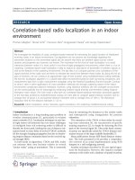
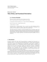
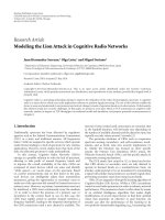
Figure 3: SDR/CR receiver front-end.
Figure 3 shows how it works: coming from the antenna, the
RF signal is first bandpass filtered and then amplified. Fol-
lowing a two-way signal splitter, the next step is an analog
mixing with the local ly generated RF frequency in the in-
phase (I) path and with the same frequency phase shifted by
−π/2 in the quadrature (Q) path. Afterwards, the I and Q
components of the signal are lowpass filtered and A/D con-
verted. The sampling rate of the A/D converters should be
fixed for all signals and has to be chosen in such a way that the
conditions of Shannon’s sampling theorem are fulfilled for
the broadest signal to be processed. Before the sampling rate
can be adapted to the signal’s standard, the impairments of
the two-branch signal processing that come from the analog
mixers and filters as well as from the A/D converters them-
selves have to be corrected [4].
The reason for the Sampling rate adaptation is that the
signal processor should work at the minimum possible rate.
For a given standard, this minimum sampling rate depends
on f
c
= 1/T
c
, the sy mbol or chip rate, respectively. Usually a
sampling rate of f
s
= 4 f
c
is sufficient for the subsequent sig-
nal processing where, after the precise synchronization, the
sampling rate may be reduced once more by a factor of 4.
If the fraction of the sampling rates at the adaptor’s output
and input is rational (or may be sufficiently close approxi-
mated by a rational number), the sampling r ate adaptation
can be implemented by an increasing of the sampling rate
followed by an interpolation lowpass filter and a decreasing
of the sampling rate. If the interpolation lowpass is imple-
mented by an FIR filter, the impulse response usually be-
comes quite long. The solution is to take the up and down
sampling into account within the filter process. Since the up-
sampled signal is usually generated by the insertion of zeros,
the processing of these zeros can be omitted within the fil-
ter. This leads to the polyphase structure of Figure 4.Because
different input/output ratios have to be realized for differ-
ent standards, the number of filter coefficients that must be
stored may become large. If necessary, a direct computation
of the filter coefficients can be more efficient than their ad-
vance storage [5]. After the sampling rate adaptation, the sig-
nal is processed within the complex baseband unit (demod-
ulation and decoding). The SDR data processing within the
higher protocol layers [6] is not considered in the present pa-
per.
z
−1
z
−1
z
−1
···
···
···
···
×× × ×
++ +
g
j
g
J+ j
g
2J+ j
g
(L−1)J+ j
Figure 4: Polyphase filter for sampling rate adaptation.
The SDR transmitter branch consists of the procedures
inverse to that of the receiver branch. That is, the signal to be
transmitted is generated as a complex baseband signal, from
which, for example, the real part is taken to be shifted to the
(transmission) RF.
For SDRs, reconfigurability means that the radio is able
to process signals of different standards or even signals that
are not standardized but exist in specific applications. One
method to implement reconfigurability is parameterization
of standards. We look at a communication standard as a set
of documents that comprehensively describe all functions of
a radio system in such a way that a manufacturer can de-
velop terminals or infrastructure equipment on this basis.
Standardization is one necessary condition to make a com-
munication system successful on the market, as exemplified
by GSM. Standardization pertains to all kinds of communi-
cation systems, that is, especial ly to personal, local, cellular,
or global wireless networks. Of course, a standard has to con-
tain precise descriptions of all the functions of the system.
Especially for a mobile system, both the air interface and the
protocol stack have to be specified. Parameterization means
that every standard is looked upon as one member of a family
of standards [7]. The signal processing structure of the fam-
ily is then developed in such a way that this structure may be
switched by parameters to realize the different standards.
When developing an SDR, one has to pay attention to the
fact that there are substantial differences between the second-
generation FDMA/TDMA standards (GSM or IS-136), the
third-generation CDMA standards (UMTS or cdma2000),
and the OFDM-modulated WLAN standards (IEEE 802.11a
or HiperLAN/2) (cf. Tabl e 1). Within UMTS, spreading at
the transmitter and despreading at the receiver have to be
realized. IFFT and FFT operations are necessary for WLAN
transceivers. Aside from such fundamental differences, sim-
ilarities among communication standards are predominant.
For example, when looking at the signal processing chains,
we remark that the error correction codes of all the second-
generation standards are very similar: a combination of a
block code for the most important bits and a convolutional
code for the larger part of the voice bits is applied. Channel
coding for data transmission is done by a powerful convolu-
tional code. UTRA, as a third-generation air interface, offers
net data rates of up to 2 Mbps and guarantees BERs, of up
to 10
−6
for specific applications. To reach these BERs turbo
codes are employed for data transmission. Of course, within
an SDR al l these procedures have to be integrated into a gen-
eral encoding/decoding structure. Also a common modula-
tor/demodulator structure has to be specified. Solutions to
these tasks are given, for example, in [2, 3, 7].
280 EURASIP Journal on Wireless Communications and Networking
4. THE SOFTWARE COMMUNICATIONS
ARCHITECTURE
The Joint Tactical Radio System (JTRS) represents the fu-
ture (mobile) communications infrastructure of the US joint
forces. Introducing JTRS stands for an essential step towards
the unification of radio communication systems, the trans-
parency of services, and the exchangeability of components.
The development of the JTRS is accompanied and supervised
by the US forces’ Joint Program Office (JPO).
Development, production, and delivery continue to be
the tasks of competing industrial communications software
and hardware suppliers. An important new asp ect added by
the JTRS set-up is that the suppliers are guided to aim for
a most perfect interchangeability of components due to the
supervision function of the JPO. The tool used by the JPO is
the software communications architecture (SCA) [8], an open
framework that prescribes the developing engineers how the
hardware or software blocks have to act together within the
JTRS. The communication devices emerging from this phi-
losophy are clearly SDRs.
A major group of suppliers and developers of communi-
cation software and hardware founded the SDR Forum [9]to
promote their interests. The importance of the SDR Forum,
however, reaches well beyond the application of SDRs in the
JTRS. This is underlined by the SDR Forum membership of
European and Asian industrial and research institutions that
usually are mainly interested in the evolution of commercial
mobile communication networks.
The SCA describes how waveforms aretobeimplemented
onto appropriate hardware devices. A waveform is defined
by the determination of the lower three layers (network,
data link, physical) of the ISO/OSI model. Therefore, wave-
form is a synonym of standard or air interface. Based on
the waveform definition, a transmission method is com-
pletely determined. The definition of a waveform, there-
fore, lays down the modulation, coding, access, and duplex
modes as well as the protocol structure of the transmission
method.
The SCA defines the software structure of an SDR that
may be usable within the JTRS. The underlying hardware
as well as the software is described in object-oriented terms.
Moreover, the structures of application program interfaces
(APIs) and of the securit y environment are described. Each
component has to be documented in a generally accessible
form.
The JTRS operating environment (OE) defined in the
SCA consists of three main components:
(i) a real-time operating system,
(ii) a real-time request broker,
(iii) the SCA core framework.
When developing an SCA compliant radio device the
supplier gets the operating system and the CORBA middle-
ware from the commercial market. The core framework as
well as the waveform is developed by him or he also gets it
from the market or (in future) it may be contributed by the
JPO.
The SCA is the description of an open architecture with
distributed components. It strictly separates applications
(waveforms) from the processing platform (hardware, oper-
ating system, object request broker, core framework). It seg-
ments the application functions and defines common inter-
faces for the management and the employment of software
components. It defines common services and makes use of
APIs to support the portability of hardware and software
components and of applications.
The connections between the applications and the core
framework within the SCA are given by the APIs. Standard-
ized APIs are essential in assuring the portability of applica-
tions as well as for the exchangeability of devices. APIs guar-
antee that application and service progra ms may commu-
nicate with one another, independent of the operating sys-
tem and the programming language used. APIs are waveform
specific since uniform APIs for all waveforms would be inef-
ficient for implementations with bounded resources. There-
fore, the goal is to have a standard set of APIs for each wave-
form. The single APIs are essential ly given by the layers of the
ISO/OSI model.
(i) A PHY API supports initialization and configuration
of the system in non-real-time. In real-time it takes care of
the transformation of symbols (or bits) to RF in the t rans-
mitter branch. In the receiver branch it transforms RF signals
to symbols (bits).
(ii) A MAC API supports all the MAC functions of the
ISO/OSI layer model (e.g., timeslot control in TDMA or FEC
control).
(iii) An LLC API makes available an interface for the
waveform’s link layer performance (according to the ISO/OSI
layer model: data link services) on component level.
(iv) A network API makes available an interface for the
waveform’s network performance on component level.
(v) A security API serves for the integration of data secu-
rity procedures (INFOSEC, TRANSEC).
(vi) An input/output API supports the input and output
of audio, video, or other data.
The security relevant SCA aspects are written down in the
SCA securit y supplement [8]. The SCA security functions and
algorithms are of course defined with respect to the military
security requirements of JTRS.
5. USER CENTRIC AND TECHNOLOGY CENTRIC
COGNITIVE RADIO PROPERTIES
The description of CR given by Mitola and Maguire in their
seminal paper [10] mainly focuses on the radio knowledge
representation language (RKRL). CR is looked upon as a small
part of the physical world using and providing information
over very different time scales. Equipped with var ious sen-
sors, a CR acquires knowledge from its environment. Em-
ploying software agents, it accesses data bases and contacts
other sources of information. In this context, CR seems to
become the indispensable electronic aid of its owner. Read-
ing [10] leads to the impression that a CR must be a complex
device that helps to overcome all problems of everyday life, all
the same whether they are recognized by the CR’s owner or
SDR—Basics and Evolution to Cognitive Radio 281
not. Of course, these visions as well as the recognition cycle for
CRs in [11] are strongly intended to stimulate new research
and development. For a more pragmatic point of view, how-
ever, we approach CR in a different way.
The properties of CRs may be divided into two groups:
(i) user centric properties that comprise support func-
tions like finding the address of a n appropriate restau-
rant or a movie theater, recommendation of a travel
route, or supervision of appointments,
(ii) technology centric properties like spectrum monitor-
ing, localization, and tracking, awareness of processing
capabilities for the partitioning or the scheduling of
processes, information gathering, and knowledge pro-
cessing.
From our point of view, many of the user centric proper-
ties can be implemented by using queries to data bases. This
type of intelligence can be kept in the networks and activated
by calls. In transceiver development, much more difficult de-
sign choices need to be made to realize the wanted technol-
ogy centric properties of a CR. Therefore, we concentrate on
the latter in the following sections.
6. THE NEED FOR ADVANCED SPECTRUM
MANAGEMENT
Today, spectrum is regulated by governmental agencies. Spec-
trum is assigned to users or licensed to them on a long-
term basis normally for huge regions like countries. Doing
this, resources are wasted, because large-frequency regions
are used very sporadically. The vision is to assign appropriate
resourcestoendusersonlyaslongastheyareneededfora
geographical ly bounded region, that is, a personal, local, re-
gional, or global cell. The spectrum access is then organized
by the network, that is, by the users. First examples for self-
regulation in mobile radio communications are to be found
in the ISM (2400–2483.5 MHz) and in the WLAN (5150–
5350 MHz and 5470–5725 MHz) bands.
Future advanced spectrum management will comprise
[12] the following.
(i) Spect rum reallocation: the reallocation of bandwidth
from government or other long-standing users to new
services such as mobile communications, broadband
internet access, and video distribution.
(ii) Spectrum leases: the relaxation of the technical and
commercial limitations on existing licensees to use
their spectrum for new or hybrid (e.g., satellite and
terrestrial) services and granting most mobile radio li-
censees the right to lease their spectrum to third par-
ties.
(iii) Spectrum sharing: the allocation of an unprecedented
amount of spectrum that could be used for unlicensed
or shared services.
If we look upon the users’ behavior in an FDMA/TDMA
system over the time/frequency plane (cf. Figure 5), we
may find out that a considerable part of the area remains
f
0
f
u
Frequency
0
Time
Figure 5: FDMA/TDMA signals over the time/frequency plane,
spectrum pool.
unused [12, 13]. This unused area marks the pool from
which frequencies can be allocated to secondary users (SUs),
for example, in a hotspot. In the following we denote the
FDMA/TDMA users as primary users (PUs). In order to
make the implementation of the SUs’ system into the PUs’
system feasible, two main assumptions should be fulfilled:
(i) the PUs’ system is not disturbed by the SUs’ system,
(ii) the PUs’ system remains unchanged (i.e., all signal
processing that has to be done to avoid disturbances
of the PUs communications must be implemented in
the SUs’ system).
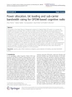
Now we assume that the transmission method within the
SUs’ system is OFDM. Figure 6 gives a brief overview over an
OFDM transmitter: the sequential data stream is converted
to a parallel stream, the vectors of which are interpreted as
signals in the frequency domain. By applying an inverse fast
Fourier transform (IFFT), these data are tra nsformed into
the time domain and sent over the air on a set of orthogonal
carriers with separation ∆ f on the frequency axis. If some
carriers should not be used, it is necessar y to transmit zeros
on these carriers. This is the strategy to protect the PUs’ sys-
tem from disturbances originating from the SUs’ system. In
order to make the SUs’ system work, the following problems
have to be solved.
(i) The reliable detection of upcoming PUs’ signals
within an extremely short time interval. (This means that
the detection has to be performed with a very high detection
probability ensuring a moderate false alarm probability.)
(ii) The consideration of hidden stations.
(iii) The signaling of the present transmission situation
in the PUs’ system to all stations of the SUs’ system such that
these do not use the frequencies occupied by the PUs.
The solutions to these problems have recently been found
[13]. The keywords for these solutions are distributed detec-
tion, boosting of the detection results and combining them
in the hotspot’s access point to an occupancy vector, and dis-
tributing the occupancy vector to all mobile stations in the
hotspot.
282 EURASIP Journal on Wireless Communications and Networking
Bit
sequence
1
m
.
.
.
1
m
.
.
.
1
m
.
.
.
Cod
Cod
Cod
Serial-to-parallel conversion
IDFT (IFFT)
Parallel-to-serial conversion
D/A
RF-
Mod.
(a)
∆ f
f
−3
f
−2
f
−1
f
0
f
1
f
2
f
3
f
······
(b)
Figure 6: OFDM. (a) Transmitter. (b) Spectrum.
The central point in our present discussion is that the SUs
system’s transceivers have in some sense to act like CRs. They
have to sense their spect ral neighborhood for PUs’ signals
and to react upon their findings.
7. TECHNOLOGY CENTRIC COGNITIVE RADIO
In a more advanced spectrum sharing system, CRs have to
apply more advanced algorithms. If a portion of the spec-
trum may be accessed by any access mode, the following
procedure becomes imaginable: starting from the transmis-
sion demand of its user, the CR decides about the data rate,
the transmission mode, and therefore about the bandwidth
of the transmission. Afterwards it has to find an appropri-
ate resource for its transmission. This presumes that the CR
knows where it is (self-location), what it is able to do (self-
awareness), and where the reachable base stations are. To get
more information about possible interferences it should, for
example, be able to detect signals active in adjacent frequency
bands and to recognize their transmission standards [14].
Summing up, a CR should have implemented the follow-
ing technologies (possibly among others):
(i) location sensors (e.g., GPS or Galileo);
(ii) equipment to monitor its spectral environment in an
intelligent
2
way;
2
Intelligent means that searching for usable frequency bands is not done
by just scanning the whole spectrum.
Control
SDR
core
Spectrum
monitoring
Localization
Information and knowledge processing
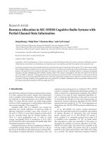
Figure 7: Technology centric cognitive radio.
(iii) in order to track the location’s or the spectral env iron-
ment’s developments, learning and reasoning algorithms have
to be implemented;
(iv) when complying with a communications etiquette, it
has to listen before talk as well as to prevent the disturbance
of hidden stations;
(v) in order to be fair it has to compromise its own de-
mands with the demands of other users, most probably in
making decisions in a competitive environment using the re-
sults of game theory [15];
(vi) it has to keep its owner informed via a highly sophis-
ticated man-machine interface.
A first block diagram of a technology centric CR is given
in Figure 7. One of the most important decisions that have to
be made in an open access environment is whether a control
channel is to be implemented or not. The most challenging
development is that of the information and knowledge pro-
cessing.
8. CONCLUSIONS
Standardization of a transmission mode is necessary to en-
sure its success on the market. From standards we can learn
about the main parameters of a system and, by comparing
different standards, we may conclude about similarities and
dissimilarities within their signal processing chains. Keep-
ing this knowledge in mind, we are able to construct PaC-
SDRs. A far more general setup is given by the SCA which is
a fr amework for the reconfigurablity of transceivers and for
the portability of waveforms from one hardware platform to
another. Starting from SDRs, the next step in the evolution
of intelligent transmission devices leads to CRs that may be
looked upon as a small part of the physical world using and
providing information over very different time scales. Since
this approach seems to be very futuristic, we take a look at
the urgent problem of efficient spectrum usage. In order to
introduce advanced spectrum management procedures (e.g.,
spectrum pooling), the employment of CRs that at least are
able to monitor their electromagnetic environments and to
track their own locations is necessary. Therefore, the devel-
opment of technology centric CRs is proposed here as a first
step towards general CRs.
SDR—Basics and Evolution to Cognitive Radio 283
ACKNOWLEDGMENT
The author gratefully acknowledges the influence that the 6th
European Framework’s Integrated Project End-to-End Recon-
figurability (E
2
R) as well as the Software-Defined Radio Fo-
rum have on his present work.
REFERENCES
[1] C.HeegardandS.B.Wicker,Turbo Coding,KluwerAcademic,
Boston, Mass, USA, 1999.
[2] F. K. Jondral, “Parametrization—a technique for SDR imple-
mentation,” in Software Defined Radio—Enabling Technolo-
gies, W. Tuttlebee, Ed., pp. 232–256, John Wiley & Sons, Lon-
don, UK, 2002.
[3] A. Wiesler and F. K. Jondral, “A software radio for second-and
third-generation mobile systems,” IEEE Trans. Veh. Technol.,
vol. 51, no. 4, pp. 738–748, 2002.
[4] P. Rykaczewski, D. Pienkowski, R. Circa, and B. Steinke, “Sig-
nal path optimization in software defined radio systems,”
IEEE Trans. Microwave Theory Tech., vol. 53, no. 3, pp. 1056–
1064, 2005.
[5] T. Hentschel and G. Fettweis, “Sample rate conversion for
software radio,” IEEE Commun. Mag., vol. 38, no. 8, pp. 142–
150, 2000.
[6] M. Sieber, “Design of a generic protocol stack for an adaptive
terminal,” in Proc. 1st Karlsruhe Workshop on Software Radios,
pp. 31–34, Institut f
¨
ur Nachrichtentechnik, Universit
¨
at Karl-
sruhe (T H), Karlsruhe, Germany, March 2000.
[7] F. K. Jondral, R. Machauer, and A. Wiesler, Software Radio—
Adaptivit
¨
at durch Parametrisierung, J. Schlembach Fachverlag,
Weil der Stadt, Germany, 2002.
[8] “Software communications architecture specification,
jtrs-5000sca v3.0,” Joint Tactical Radio System (JTRS)
Joint Program Office, August 2004, available online on
.
[9] “Software Defined Radio Forum,” available online on
.
[10] J. Mitola III and G. Q. Maguire, “Cognitive radio: making
software radios more personal,” IEEE Pers. Commun., vol. 6,
no. 4, pp. 13–18, 1999.
[11] J. Mitola III, “Cognitive radio: an integrated agent architec-
ture for software defined radio,” Ph.D. dissertation, Computer
Communication System Laboratory, Department of Telein-
formatics, Royal Institute of Technology (KTH), Stockholm,
Sweden, May 2000.
[12] G. Staple and K. Werbach, “The end of spectrum scarcity,”
IEEE Spectr., vol. 41, no. 3, pp. 48–52, 2004.
[13] T. A. Weiss and F. K. Jondral, “Spectrum pooling: an inno-
vative strategy for the enhancement of spectrum efficiency,”
IEEE Commun. Mag., vol. 42, no. 3, pp. 8–14, 2004.
[14] M.
¨
Oner and F. K. Jondral, “Air interface recognition for a
software radio system exploiting cyclostationarity,” in Proc.
15th IEEE International Symposium on Personal, Indoor and
Mobile Radio Communications (PIMRC ’04), vol. 3, pp. 1947–
1951, Barcelona, Spain, September 2004.
[15] J. Neel, J. Reed, and R. Gilles, “The role of game theory in
the analysis of software radio networks,” in Proc. Software De-
fined Radio Forum Technical Conference and Product Exhibi-
tion (SDR ’02), vol. 2, pp. NP–3–02, San Diego, Calif, USA,
November 2002.
[16] J. Mitola III, Software Radio Architecture: Object-Oriented Ap-
proaches to Wireless Systems Engineering ,JohnWiley&Sons,
New York, NY, USA, 2000.
[17] J. Mitola III and Z. Zvonar, Eds., Software Radio Technologies:
Selected Readings, John Wiley & Sons, New York, NY, USA,
2000.
[18] J. Mitola III and W. Tuttlebee, Eds., Software Defined Radio:
Origins, Drivers and International Perspectives, John Wiley &
Sons, Chichester, UK, 2002.
[19] W. Tuttlebee, Ed., Software Defined Radio: Enabling Technolo-
gies, John Wiley & Sons, Chichester, UK, 2002.
[20] M. Dillinger, K. Madani, and N. Alonistioti, Eds., Software De-
fined Radio: Architectures, Systems and Functions,JohnWiley
& Sons, Chichester, UK, 2003.
[21] J. Reed, Software Radio—a Modern Approach to Radio Engi-
neering, Prentice-Hall, Upper Saddle River, NJ, USA, 2002.
[22] H. Harada and R. Prasad, Simulation and Software Radio for
Mobile Communications, Artech House, Boston, Mass, USA,
2002.
[23] S. Haykin, “Cognitive radio: brain-empowered wireless com-
munications,” IEEE J. Select. Areas Commun.,vol.23,no.2,
pp. 201–220, 2005.
Friedrich K. Jondral received a Diploma
and a Doctoral degree in mathematics from
the Technische Universit
¨
at Braunschweig,
Germany, in 1975 and 1979, respectively.
During the winter semester 1977/78, he was
a Visiting Researcher in the Department
of Mathematics, Nagoya University, Japan.
From 1979 to 1992, Dr. Jondral was an em-
ployee of AEG-Telefunken (now European
Aeronautic Defence and Space Company
(EADS)), Ulm, Germany, where he held various research and devel-
opment, as well as management positions. Since 1993, Dr. Jondral
has been Full Professor and Head of the Institut f
¨
ur Nachrichten-
technik at the Universit
¨
at Karlsruhe (TH), Germany. There, from
2000 to 2002, he served as the Dean of the Department of Elect ri-
cal Engineering and Information Technology. During the summer
semester of 2004, Dr. Jondral was a Visiting Faculty in the Mobile
and Portable Radio Research Group of Virginia Tech, Blacksburg,
Va. His current research interests are in the fields of ultra-wide-
band communications, software-defined and cognitive radio, sig-
nal analysis, pattern recognition, network capacity optimization,
and dynamic channel allocation. Dr. Jondral is a Senior Member
of the IEEE; he currently serves as an Associate Editor of the IEEE
Communications Letters and as a Member of the Software-Defined
Radio Forum’s Board of Directors.