ASM2 IOT MERIT BTEC FPT
Bạn đang xem bản rút gọn của tài liệu. Xem và tải ngay bản đầy đủ của tài liệu tại đây (4.63 MB, 42 trang )
ASSIGNMENT 2 FRONT SHEET
Qualification BTEC Level 5 HND Diploma in Computing
Unit number and title Unit 43: Internet of Things
Submission date 18/11/2023 Date Received 1st submission 18/11/2023
Re-submission Date Date Received 2nd submission
Student Name Nguyen Thanh Tai Student ID BD00196
Class IT05202 Assessor name Truong Dang Hieu
Student declaration
I certify that the assignment submission is entirely my own work and I fully understand the consequences of plagiarism. I understand that
making a false declaration is a form of malpractice.
Student’s signature
Grading grid
P3 P4 P5 P6 M3 M4 M5 D2
Page | 1
Perfomed Student: Nguyen Thanh Tai
Summative Feedback: Resubmission Feedback:
Grade: Assessor Signature: Date:
Internal Verifier’s Comments:
Signature & Date: Page | 2
Perfomed Student: Nguyen Thanh Tai
TABLE OF CONTENT
Contents
TABLE OF CONTENT ..................................................................................................................................3
LIST OF TABLES .........................................................................................................................................4
LIST OF FIGURE .........................................................................................................................................5
LIST OF THE ACRONYM .............................................................................................................................6
INTRODUCTION ........................................................................................................................................7
Chapter 1: Outline a plan for an appropriate IoT application, using common architecture, frameworks,
tools, hardware and APIs..........................................................................................................................8
3.1 Inves gate architecture, frameworks, tools, hardware and API techniques available to develop
IoT applica ons.(P3).............................................................................................................................8
4.1 Determine a specific problem to solve using IoT.(P4) .................................................................11
4.1.1 Plan an IoT applica on for a specific target end user in the form of a document. ..............11
4.1.2 System Design .......................................................................................................................13
5.1 Select the most appropriate IoT architecture, frameworks, tools, hardware and API techniques
to include in an applica on to solve this problem. (M3) ...................................................................15
5.1.1 Select hardware device .........................................................................................................15
5.1.2 Select control so ware .........................................................................................................18
6.1 Apply selected techniques to create an IoT applica on development plan. (M4)......................19
Chapter 2: Develop an IoT application using any combination of hardware, software, data, platforms
and services. ...........................................................................................................................................27
6.1 Employ an appropriate set of tools to develop a plan into an IoT applica on.(P5) ....................27
6.1.1 Result.....................................................................................................................................27
6.1.2 Source code of the system ....................................................................................................29
7.1 Run end user experiments and examines feedback.(P6).............................................................33
7.1.1 Test opera on. ......................................................................................................................33
7.1.2 user opinion survey. ..............................................................................................................34
8.1 Reconcile and evaluate end user feedback and determine advantages and disadvantages of your
chosen IoT techniques (M5)...............................................................................................................37
9.1 Make mul ple itera ons of your IoT applica on and modify each itera on with enhancements
gathered from user feedback and experimenta on. (D2).................................................................38
CONCLUSION ..........................................................................................................................................40
CRITICAL EVALUATION............................................................................................................................41
REFERENCES............................................................................................................................................ 42
Page | 3
Perfomed Student: Nguyen Thanh Tai
LIST OF TABLES
Page | 4
Perfomed Student: Nguyen Thanh Tai
LIST OF FIGURE
Figure 0.1: Block Diagram...................................................................................................................... 13
Figure 0.2:Algorithm Diagram. .............................................................................................................. 14
Figure 0.3: Arduino................................................................................................................................ 16
Figure 0.4: ESP8266............................................................................................................................... 17
Figure 0.5: Blynk. ................................................................................................................................... 19
Figure 0.6: Project planning. ................................................................................................................. 20
Figure 0.7: Buy equipment. ................................................................................................................... 21
Figure 0.8: Hardware assembly............................................................................................................. 22
Figure 0.9: Write Program..................................................................................................................... 23
Figure 0.10: Power Supplies. ................................................................................................................. 24
Figure 0.11: Select port. ........................................................................................................................ 25
Figure 0.12: Uploads code..................................................................................................................... 25
Figure 0.13: Serial.................................................................................................................................. 25
Figure 0.14: Keypad............................................................................................................................... 26
Figure 0.15: Picture of project (1). ........................................................................................................ 27
Figure 0.16: Picture of project (2). ........................................................................................................ 28
Figure 0.17: Picture of project (3). ........................................................................................................ 28
Figure 0.18: Code of the system(1). ...................................................................................................... 29
Figure 0.19: Code of the system(2). ...................................................................................................... 29
Figure 0.20: Code of the system(3). ...................................................................................................... 30
Figure 0.21: Code of the system(4). ...................................................................................................... 30
Figure 0.22: Code of the system(5). ...................................................................................................... 31
Figure 0.23: Code of the system(6). ...................................................................................................... 31
Figure 0.24: Code of the system(7). ...................................................................................................... 32
Figure 0.25: Code of the system(8). ...................................................................................................... 32
Figure 0.26: Code of the system(10). .................................................................................................... 33
Figure 0.27: Survey (1)........................................................................................................................... 35
Figure 0.28: Survey(2). .......................................................................................................................... 35
Figure 0.29: Survey (3)........................................................................................................................... 35
Figure 0.30: Survey(4). .......................................................................................................................... 36
Figure 0.31: Survey(5). .......................................................................................................................... 36
Figure 0.32: User comment(1); ............................................................................................................. 38
Figure 0.33: User comment(2). ............................................................................................................. 39
Page | 5
Perfomed Student: Nguyen Thanh Tai
IoT LIST OF THE ACRONYM
IoTaaS
API Internet of Things
GPS Internet of Things as a Service
Applica on Programming Interface
Global Posi oning System
Page | 6
Perfomed Student: Nguyen Thanh Tai
INTRODUCTION
Not long ago, the concept of the Internet of Things (IoT) became a familiar part of our daily lives. IoT
represents the connec on of billions of devices, sensors and informa on systems over the Internet,
allowing them to exchange informa on and perform tasks that previously seemed impossible. The
subject of IoT is not only an important step forward in technology development, but also an
opportunity for us to understand how to connect devices and applica ons together to create a smart
and convenient world. . In this course, we will explore the fundamental aspects of IoT, from sensors
and connec vity to data analy cs and prac cal applica ons. We will see that IoT is not just a new field
of technology but also an opportunity to create innova ve and exci ng solu ons for the real world.
IoT has changed the way we interact with our surroundings and brought many benefits in many fields,
from industry, agriculture, healthcare to smart homes and the world of technology. In this course, we
will learn how to build IoT systems, become familiar with the tools and techniques needed to develop
IoT applica ons, and understand how IoT projects can help solve real-world problems. interna onal.
Let's enter the world of IoT together and explore its endless poten al to create future advancement
and innova on.
At the heart of my role is the exci ng challenge of envisioning, planning and developing IoT products,
services and applica ons tailored to our customers' unique needs. Under the guidance of my astute
manager, I embarked on a thrilling journey to create a groundbreaking IoT solu on for a poten al
client.
Page | 7
Perfomed Student: Nguyen Thanh Tai
Chapter 1: Outline a plan for an appropriate IoT application, using
common architecture, frameworks, tools, hardware and APIs.
3.1 Inves gate architecture, frameworks, tools, hardware and API techniques
available to develop IoT applica ons.(P3)
Our idea is an infrared an -the system that takes advantage of cu ng-edge technology to improve security
and protec on. This system detects unlawful movement and intrusions using infrared sensors, promp ng quick
warnings and reac ons. The project is built with the goal of delivering dependable and efficient security, giving
consumers piece of mind. With the use of infrared technology, it provides a strong and sophis cated solu on
for protec ng important assets and premises.
Architectural models
- 3-storey model:
Sensor Floor: At this floor, use infrared sensors to detect the movement of people or objects in the
area to be protected.
Middle Layer (Gateway): Data from the sensor is sent to a Gateway, usually an intermediate IoT device
or network computer, to process and transmit data to the applica on layer.
Applica on Layer: At this layer, there is an IoT applica on dedicated to the an -the system. This
applica on receives data from the Gateway and manages the an -the system, triggers alarms and
sends no fica ons to users.
- 4-storey model:
Sensor Floor: At this floor, infrared sensors are used to detect mo on.
Network Layer: Data from the sensor is sent to an intermediate IoT device or IoT network node (IoT
node). The network layer handles communica on and transfers data to the background layer.
Back-End: Data from the network layer is fed into the IoT data storage system or IoT server. Here, data
is stored, processed and analyzed to determine if there is any suspicious movement.
Applica on Layer: This layer manages and processes data, checks for unwanted mo on events, and
sends alerts to users via mobile apps or through no fica on mechanisms.
FrameWork
To create a complete and efficient IoT system, you can use the following classes:
Sensor layer: This layer contains IoT devices or sensors to collect data from the environment. Chungs I
use infrared sensors to develop the project.
Connec vity Layer: This layer manages how data from the sensor is transmi ed to the IoT system. It
Page | 8
Perfomed Student: Nguyen Thanh Tai
includes a Wi-Fi communica on protocol, and a gateway to collect and transmit data to the network or
cloud.
Analy cs Layer: This layer uses data from the Data layer to perform analysis, extract important
informa on, and create reports or predic ons. It includes data analysis tools, machine learning
algorithms, and data visualiza on.
Product Infrastructure Layer: The Product Infrastructure Layer provides the infrastructure for managing
and controlling IoT devices. It includes device management, firmware updates and remote
configura on. This ensures that the equipment is properly installed and maintained.
Smart Apps Layer: Smart applica on layer includes applica ons that interact with IoT systems. These
applica ons can be web or mobile applica ons, allowing users to monitor and control devices, receive
no fica ons, and access analy cal data.
For crea ng Internet of Things (IoT) applica ons and solu ons, there are numerous frameworks and pla orms
available. These frameworks offer tools, libraries, and services that make IoT crea on and maintenance easier.
Here are several well-known IoT frameworks:
Arduino: Arduino is an open-source hardware and so ware pla orm that is popular for prototyping IoT
devices. It includes a wide range of compa ble sensors and shields, making it easy to build IoT
prototypes.
ESP8266: is a Wi-Fi module with Internet connec vity and is integrated on some embedded boards such
as NodeMCU, Wemos, and ESP-01. The ESP8266 can act as an access point, a client connec ng to
another access point, or both. It is widely used in IoT (Internet of Things) applica ons such as smart
sensors, device control systems, or remote control applica ons. This module is cheap and very easy to
use, along with compa bility with many different types of microcontrollers.
Tools
I use the following tools to make the project
- Infrared Sensor: Used to detect movement.
- IoT Gateway device or Node: Used to collect data from sensors and transmit to the network or pla orm
layer.
- IoT Server or Storage System: Stores and processes data from sensors.
- Mobile device (Smartphone or Tablet): Use to receive alerts and no fica ons from IoT applica ons.
Hardware Page | 9
Several types of Sensors and Output loads :
Perfomed Student: Nguyen Thanh Tai
Sensor: Humidity Sensor, Gas Sensor, Water Sensor, Light Sensor, Mo on Sensor, Touch Sensor,Utralsonic
Sensor, Temperature Sensor,…
Output loads: Led, Servo Motor, Buzzer, Stepper Motor, Relay, GPIO,….
APIs
- Devices and apps in an Internet of Things (IoT) ecosystem communicate and exchange data using an API
(Applica on Programming Interface) set of rules and interfaces. IoT APIs facilitate communica on and
interac on between various IoT system elements, such as sensors, devices, services, and apps.
- In the context of IoT, APIs essen ally specify how informa on is sent and received between devices and
pla orms, as well as how commands and no fica ons can be sent and received. IOT APIs usually offer the ability
to access and manage data gathered from devices as well as remotely manage, control, and monitor them.
- Here are some common APIs:
MQTT (Message Queuing Telemetry Transport): MQTT is a lightweight and powerful communica on
protocol, commonly used for sending messages between devices in IoT environments.
CoAP (Constrained Applica on Protocol): CoAP is a lightweight communica on protocol, op mized for
devices with limited resources. It is commonly used for communica on between IoT devices and servers.
HTTP/HTTPS (HyperText Transfer Protocol/Secure): HTTP and HTTPS protocols are commonly used to
communicate between IoT devices and web service pla orms.
RESTful API (Representa onal State Transfer): RESTful API provides a communica on architecture based on
HTTP methods. It is commonly used to create interfaces between devices and web applica ons.
WebSocket: WebSocket is a protocol that allows devices and servers to communicate in real me. It is
suitable for applica ons that need low latency.
AMQP (Advanced Message Queuing Protocol): AMQP is a standard protocol for communica on between
applica ons and services, o en used in large IoT systems.
Bluetooth APIs: For IoT applica ons that use Bluetooth connec vity, APIs such as the Bluetooth Low Energy
(BLE) API are provided to manage connec vity and communica ons.
- Blynk is an IoT (Internet of Things) pla orm that helps connect and manage smart devices via the internet. Here
are some preliminary characteris cs about Blynk Cloud:
Friendly User Interface: Blynk provides a simple and friendly user interface, helping users easily interact
with their IoT devices.
Mul -Pla orm Support: Blynk supports mul -pla orm, including iOS, Android and web pla orms. This
helps users control and monitor devices from any mobile device with an internet connec on.
Page | 10
Perfomed Student: Nguyen Thanh Tai
Extensive Widgets Library: Blynk offers a wide range of widgets (interface elements) such as bu ons, sliders,
LEDs, charts and more. These widgets help create flexible user interfaces for IoT applica ons.
Easy Device Connec on: Blynk makes it simple to establish connec ons between IoT devices and Blynk
Cloud. Users can use protocols such as MQTT, WebSocket, or Blynk's own protocol to connect their devices.
Security: Blynk supports security measures to ensure data and device safety. This includes the use of
verifica on codes, secure connec ons via HTTPS, and access management.
Project Management: Blynk allows users to create and manage many different IoT projects, each of which
can contain mul ple devices.
Mul -Source Cloud Service Support: Blynk can connect to various cloud services such as Amazon AWS,
Google Cloud, and Microso Azure to store data or deploy extended func ons.
Open Source Code: Blynk's source code is available and open source, allowing users to customize and
expand according to their needs.
4.1 Determine a specific problem to solve using IoT.(P4)
4.1.1 Plan an IoT applica on for a specific target end user in the form of a document.
IoT Applica on Plan: Infrared An -The System
Problem Statement
The s and unauthorized access to homes, offices, and valuable assets are persistent issues affec ng the security
of individuals and organiza ons. To address this problem, we propose the development of an Infrared An -
The System using IoT technology. This system aims to provide an efficient and reliable solu on for detec ng
and preven ng intrusions.
Target and user
Our target end users for this IoT applica on include:
- Homeowners: Individuals who want to enhance the security of their homes, ensuring the safety of their
loved ones and valuable possessions.
- Small Businesses: Small business owners looking for cost-effec ve security solu ons to protect their
offices, stores, and inventory.
- Security Personnel: Security professionals who require advanced tools to monitor and secure large
proper es and facili es.
Solu on Overview
Page | 11
Perfomed Student: Nguyen Thanh Tai
Our IoT applica on will leverage Infrared (PIR) sensors to detect mo on and heat sources within a specific range.
When unauthorized movement or intrusion is detected, the system will trigger alerts and no fica ons to the
end users. The IoT aspect allows for remote monitoring and control, enhancing the overall security and peace
of mind for the users.
Key Features
- Infrared Sensors: U lize IR sensors for precise mo on and heat detec on.
- Internet Connec vity: Connect to the internet to enable remote monitoring and management.
- Real-Time Alerts: Provide real- me alerts through mobile apps or email no fica ons when intrusions
are detected.
- Remote Control: Allow end users to arm or disarm the system remotely using a mobile applica on.
- Data Logging: Record event data and mestamp to maintain a history of security-related events.
System Architecture
The proposed IoT applica on will follow a three- er architecture:
- Device Layer: This layer comprises Infrared sensors and IoT-enabled devices Arduino Uno R3 and
ESP8266.
- Middleware Layer: This layer handles data processing, event detec on, and communica on with end
users via RESTful APIs.
- Applica on Layer: End users interact with the system through a user-friendly mobile applica on or web
interface for remote monitoring and control.
Implementa on Steps
- Hardware Setup: Install Infrared sensors at strategic points in the secured area.
- Connec vity: Establish an internet connec on for the IoT devices.
- Programming: Develop the firmware for the IoT devices, including mo on detec on, data transmission,
and alert genera on.
- API Development: Create RESTful APIs for communica on between IoT devices and the user interface.
- User Interface: Develop user-friendly mobile applica ons and web interfaces for end users.
- Tes ng: Thoroughly test the system to ensure the accurate detec on of intrusions and the reliability of
alerts.
- Deployment: Install the system at the target loca ons and provide user training.
- Maintenance: Monitor the system for ongoing opera on and provide necessary maintenance.
Page | 12
Perfomed Student: Nguyen Thanh Tai
4.1.2 System Design
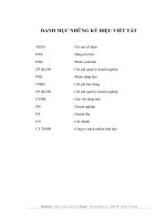
Block Diagram
Figure 0.1: Block Diagram.
In the diagram above, the infrared sensor sends informa on to the Arduino when mo on is detected. The
Arduino will process informa on from the sensor and keypad. If the authen ca on informa on is correct,
Arduino will control other devices such as LED, Buzzer, and Servo Motor. Informa on is also displayed on the
LCD screen.
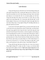
Algorithm Flowchart
Algorithm diagram presents the opera ng process of the infrared an -the IoT project. The process first starts
with boo ng and configuring the devices, then waits for the user to enter the password via the LCD screen and
keypad.
Next, the system checks the entered password and compares it with the previously set password. If the
password is correct, the system enters Standby Mode, where infrared sensors are ac vated to detect movement
in the environment.
Page | 13
Perfomed Student: Nguyen Thanh Tai
When there is a mo on event, the system ac vates an alarm, using LED lights, sound from the horn and displays
a no fica on on the mobile applica on. The user can then iden fy and unlock the door by opera ng the keypad.
This process helps ensure safety and protect assets before the .
Finally, the project will finish one cycle and be ready for the next cycles. Diagram algorithm help helps
understand the system's opera on and is the basis for op mizing and expanding features in the future.
Figure 0.2:Algorithm Diagram. Page | 14
Perfomed Student: Nguyen Thanh Tai
5.1 Select the most appropriate IoT architecture, frameworks, tools, hardware and
API techniques to include in an applica on to solve this problem. (M3)
5.1.1 Select hardware device
Input Device
PIR mo on sensor HC-SR501:
Name: PIR_Sensor
Number of connec on pins: 13(digital)
Keypad:
Name: customKeypad
Number of connec on pins ROWS: 4, 8, 7, 6(digital)
COLS: 5, 4, 3(digital
Connect to ESP8266:
Name: connect_esp
Number of connec on pins: 12(digital)
Execu on equipment
Servo Motor:
Name: Servo_Motor
Number of connec on pins: A0 (Analog)
LED :
Name: Led_Blue
Number of connec on pins: 2 (digital)
Name: Led_Red
Number of connec on pins: 11(digital)
Page | 15
Perfomed Student: Nguyen Thanh Tai
Buzzer:
Name: Buzzer
Number of connec on pins: 10(digital)
Control center
1. Arduino
Choosing Arduino for the infrared an -the IoT project was done for many specific reasons. First, Arduino is a
popular and easy-to-use pla orm that is great for embedded projects like an -the projects. Simplicity in
programming and integra on with other components reduces project complexity, especially when it involves
devices such as infrared sensors, keypads, LCD screens, LEDs, buzzers and servos.
Second, the large community around Arduino provides great documenta on and significant support. This helps
reduce development and troubleshoo ng me through sharing experiences and knowledge. At the same me,
the variety of Arduino versions allows choosing the model that suits the specific requirements of the project.
Arduino also has good compa bility with many different types of addi onal components and modules. In an
an -the project, combining an Arduino with devices such as infrared sensors and servos helps create a secure
and flexible system. This flexibility is important to ensure that the system can adapt to different requirements
and situa ons.
In short, simplicity, popularity, community support, and compa bility are the key reasons that make Arduino
the ideal choice for an infrared an -the IoT project.
Figure 0.3: Arduino
Page | 16
Perfomed Student: Nguyen Thanh Tai
2. ESP8266:
Choosing to use the ESP8266 module in an infrared anti-theft IoT project is especially reasonable and brings many
important advantages. The ESP8266 is a built-in Wi-Fi module, designed for easy integration into IoT projects,
which offers several important benefits.
First, the wireless connectivity of the ESP8266 makes the project more flexible and easier to manage remotely.
This module allows direct access to the project via Wi-Fi, helping users conveniently monitor and control the
system over the network.
Second, the ESP8266 has a compact size and low power consumption, which makes it a suitable choice for
projects that require compactness and energy efficiency. This is important in an anti-theft system, where
maintaining performance without increasing cost and complexity is key.
Third, the ESP8266 has a strong support community and many online references, which helps reduce
development time and problem solving. The popularity of the ESP8266 in the IoT community also provides high
stability and reliability.
In short, the combination of Wi-Fi connectivity, small size, energy efficiency and strong community support are
the key reasons why ESP8266 is the superior choice for anti-virus projects. This thief.
Figure 0.4: ESP8266. Page | 17
Perfomed Student: Nguyen Thanh Tai
5.1.2 Select control so ware
So ware Programming
Name: Arduino IDE 2.2.1.
Version: 2.2.1.
Advantage:
Improved user interface: Provides a new user interface, designed to make the programming process
easier and friendlier.
Support for a variety of boards: Con nue to improve compa bility with a variety of Arduino and other
boards.
Feature updates: New versions o en bring feature improvements, bug fixes, and performance.
The applica on supports control connec on via the Internet
Blynk is a popular and powerful IoT (Internet of Things) pla orm that provides Blynk Cloud to manage and
connect IoT devices. Here are some advantages of Blynk Cloud along with an introduc on to the func onal
components in the interface of Blynk Cloud and the Blynk mobile applica on:
Advantages of Blynk Cloud:
Ease of Use: Blynk Cloud is designed to be simple and easy to use, helping users quickly connect and control IoT
devices.
Secure Connec on: Blynk Cloud provides a secure connec on between devices and mobile applica ons through
secure protocols.
Cross-Pla orm Support: Supports mul ple pla orms and device types, from simple microcontrollers to complex
IoT boards.
Free Cloud Service: Blynk provides a free cloud service to users, helping them quickly deploy their IoT projects
without the need to deploy their own servers.
Blynk Cloud Interface:
Dashboard: Allows users to create and customize dashboards to remotely monitor and control IoT devices.
Project Se ngs: Where users manage general se ngs for the project, including connec on informa on and
opera ng modes. Page | 18
Perfomed Student: Nguyen Thanh Tai
Datastreams: Display and manage data from connected devices.
Blynk App on Mobile:
Virtual Pins: Virtual pins enable interac on between mobile applica ons and IoT devices.
Widgets (Interface Elements): Blynk provides a series of widgets such as bu ons, sliders, clocks, charts, for users
to easily create control interfaces.
Eventor: Allows users to set automated rules and scenarios based on events and device status.
History: Displays a history of events and data from the device.
Figure 0.5: Blynk.
6.1 Apply selected techniques to create an IoT applica on development plan. (M4)
Project Implementa on steps:
Step 1: Project planning
Page | 19
Perfomed Student: Nguyen Thanh Tai
Figure 0.6: Project planning. Page | 20
Perfomed Student: Nguyen Thanh Tai