MECHANICS OF MATERIALS CHAPTER 6 SHEARING STRESSES IN BEAMS AND THIN-WALLED MEMBERS
Bạn đang xem bản rút gọn của tài liệu. Xem và tải ngay bản đầy đủ của tài liệu tại đây (1.66 MB, 30 trang )
CHAPTER MECHANICS OF
6 MATERIALS
Shearing Stresses in
Beams and Thin-
Walled Members
MECHANICS OF MATERIALS
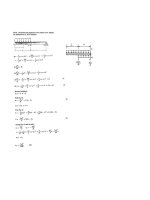
Introduction
Transverse loading applied to beam results in
normal and shearing stresses in transverse
sections.
Distribution of normal and shearing stresses
satisfies ( from equilibrium)
Fx xdA 0 M x y xz z xy dA 0
Fy xydA V
Fz xzdA 0 M y z xdA 0
M z y x M
When shearing stresses are exerted on
vertical faces of an element, equal stresses
exerted on horizontal faces
Longitudinal shearing stresses must exist in
any member subjected to transverse
loading.
46--22
MECHANICS OF MATERIALS
Vertical and Horizontal Shear Stresses
4 -3
MECHANICS OF MATERIALS
Shear Stress in Beams
Two beams glued together
along horizontal surface
When loaded, horizontal
shear stress must develop
along glued surface in
order to prevent sliding
between the beams.
MECHANICS OF MATERIALS
Shear on Horizontal Face of Beam Element
Consider prismatic beam
Equilibrium of element CDC’D’
Fx 0 H D C dA
A
H M D MC y dA
IA
Let, Q y dA
A
M D M C dM x V x
dx
H VQ x
I
q H VQ shear flow
x I
6- 5
MECHANICS OF MATERIALS
Shear on Horizontal Face of Beam Element
Shear flow,
q H VQ shear flow
x I
where
Q y dA
A
first moment of area above y1
I y2dA
A A'
second moment of full cross section
Same result found for lower area
Q Q y dA 0
A1 A2
(first moment of area wrt NA is zero)
q H VQ V (Q) q
x I I
H H
6- 6
MECHANICS OF MATERIALS
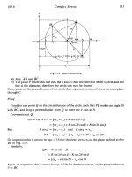
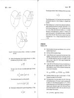
Example 6.1
Beam made of three planks, nailed
together. Spacing between nails is 25
mm. Vertical shear in beam is
V = 500 N. Find shear force in each
nail.
6- 7
MECHANICS OF MATERIALS
Example 6.1
SOLUTION:
Find horizontal force per unit length or
shear flow q on lower surface of
upper plank.
VQ (500N)(120 106 m3)
q
I 16.20 10-6 m4
Q Ay 3704 N m
0.020m 0.100m0.060m Calculate corresponding shear force in
each nail for nail spacing of 25 mm.
120 106 m3
F (0.025m)q (0.025m)(3704 N m
I 112 0.020m0.100m3 F 92.6 N
2[ 112 0.100m0.020m3
0.020m 0.100m0.060m2]
16.20 106 m4
6- 8
MECHANICS OF MATERIALS
Determination of Shearing Stress
Average shearing stress on horizontal face of
element is shearing force on horizontal face
divided by area of horzontal face.
ave H q x VQ x
A A I t x
ave VQ ; tq
It
Note averaging is across dimension t (width)
which is assumed much less than the depth, so
this averaging is allowed.
On upper and lower surfaces of beam, tyx= 0. It
follows that txy= 0 on upper and lower edges of
transverse sections.
If width of beam is comparable or large relative to
depth, the shearing stresses at D’1 and D’2 are
significantly higher than at D, i.e., the above
averaging is not good.
6- 9
MECHANICS OF MATERIALS
Shearing Stresses txy in Common Types of Beams
For a narrow rectangular beam,
VQ 3 V y2
xy 1 2
Ib 2 A c
max 3 V
2A
For I beams
ave VQ
It
max V
Aweb
6- 10
MECHANICS OF MATERIALS
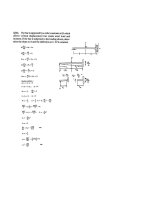
Example 6.2
Timber beam supports three
concentrated loads.
all 12 MPa all 0.8 MPa
Find minimum required depth d of
beam.
6- 11
MECHANICS OF MATERIALS
Example 6.2
Vmax 14.5 kN
M max 10.95 kNm
6- 12
MECHANICS OF MATERIALS
Example 6.2
Determine depth based on allowable normal stress.
all M max
S
61210 Pa 10.95103 Nm
0.015 m d 2
d 0.246 m 246mm
I 112 b d 3 Determine depth based on allowable shear stress.
S I 61 b d 2 all 3 Vmax
c 2A
1 0.09 md 2 0.8106 Pa 3 14500
6
2 0.09 md
0.015 md 2
d 0.322 m 322 mm
Required depth d 322 mm
6- 13
MECHANICS OF MATERIALS
Longitudinal Shear Element of Arbitrary Shape
Have examined distribution of vertical
components txy on transverse section.
Now consider horizontal components
txz .
Consider element defined by curved
surface CDD’C’.
Fx 0 H D C dA
A
So only the integration area is different,
hence result same as before, i.e.,
H VQ x q H VQ
I x I
Will use this for thin walled members
also
6- 14
MECHANICS OF MATERIALS
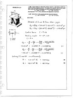
Example 6.3
Square box beam constructed from four
planks. Spacing between nails is 44
mm. Vertical shear force V = 2.5 kN.
Find shearing force in each nail.
6- 15
MECHANICS OF MATERIALS
Example 6.3
SOLUTION:
Determine the shear force per unit
length along each edge of the upper
plank.
VQ 2500 N64296 mm3 N
q 15.6
I 10332 mm 4 mm
f q 7.8 N
2 mm
For the upper plank, edge force per unit length
Q Ay 18mm76 mm47 mm Based on the spacing between nails,
determine the shear force in each
64296 mm3 nail.
For the overall beam cross-section, N
I 1 112 mm4 1 76 mm4 F f 7.8 44 mm
12 12
mm
10332 mm4 F 343.2 N
6- 16
MECHANICS OF MATERIALS
Shearing Stresses in Thin-Walled Members
Shear stress assumed constant through
thickness t, i.e., due to thinnness our
averaging is now accurate/exact.
Consider I-beam with vertical shear V.
Longitudinal shear force on element is
H VQ x
I
Corresponding shear stress is
zx xz H VQ
t x It
Previously had similar expression for
shearing stress web
xy VQ
It
NOTE: xy 0 in the flanges
xz 0 in the web
6- 17
MECHANICS OF MATERIALS
Shearing Stresses in Thin-Walled Members
The variation of shear flow across the
section depends only on the variation of
the first moment.
q t VQ
I
For a box beam, q grows smoothly from
zero at A to a maximum at C and C’ and
then decreases back to zero at E.
The sense of q in the horizontal portions
of the section may be deduced from the
sense in the vertical portions or the
sense of the shear V.
6- 18
MECHANICS OF MATERIALS
Shearing Stresses in Thin-Walled Members
For wide-flange beam, shear flow q
increases symmetrically from zero at A
and A’, reaches a maximum at C and
then decreases to zero at E and E’.
The continuity of the variation in q and
the merging of q from section branches
suggests an analogy to fluid flow.
6- 19
MECHANICS OF MATERIALS
Example 6.4
Q 108 mm19.6 mm122.2 mm
258700 mm3
Shear stress at a,
Vertical shear is 200 kN in a VQ 200103 N258.7 106 m3
W250x101 rolled-steel beam. Find
horizontal shearing stress at a. It 16410 m 0.0196 m
6 4
16.1MPa
6- 20