Introduction to AutoCAD 2011 2D and 3D Design pot
Bạn đang xem bản rút gọn của tài liệu. Xem và tải ngay bản đầy đủ của tài liệu tại đây (35.82 MB, 439 trang )
Introduction to AutoCAD 2011
Introduction to
AutoCAD 2011
2D and 3D Design
Alf Yarwood
AMSTERDAM • BOSTON • HEIDELBERG • LONDON • NEW YORK • OXFORD
PARIS • SAN DIEGO • SAN FRANCISCO • SINGAPORE • SYDNEY • TOKYO
Newnes is an imprint of Elsevier
Newnes is an imprint of Elsevier
The Boulevard, Langford Lane, Kidlington, Oxford OX5 1GB, UK
30 Corporate Drive, Suite 400, Burlington, MA 01803, USA
First edition 2010
Copyright © 2010, Alf Yarwood. Published by Elsevier Ltd. All rights reserved.
The right of Alf Yarwood to be identified as the author of this work has been asserted in accordance
with the Copyright, Designs and Patents Act 1988
No part of this publication may be reproduced, stored in a retrieval system or transmitted in any form or
by any means electronic, mechanical, photocopying, recording or otherwise without the prior written
permission of the publisher
Permissions may be sought directly from Elsevier’s Science & Technology Rights Department in
Oxford, UK: phone (44) (0) 1865 843830; fax (44) (0) 1865 853333; email:
Alternatively you can submit your request online by visiting the Elsevier web site at
permissions, and selecting Obtaining permission to use Elsevier material
Notice
No responsibility is assumed by the publisher for any injury and/or damage to persons or property
as a matter of products liability, negligence or otherwise, or from any use or operation of any methods,
products, instructions or ideas contained in the material herein. Because of rapid advances in the
medical sciences, in particular, independent verification of diagnoses and drug dosages should be made
British Library Cataloguing-in-Publication Data
A catalogue record for this book is available from the British Library
Library of Congress Cataloging-in-Publication Data
A catalog record for this book is available from the Library of Congress
ISBN: 978-0-08-096575-8
For information on all Newnes publications
visit our website at www.books.elsevier.com
Typeset by MPS Limited, a Macmillan Company, Chennai, India
www.macmillansolutions.com
Printed and bound in China
10
11 12 13 14 15 10 9 8 7 6 5 4 3 2 1
xiii
Preface
The purpose of writing this book is to produce a text suitable for students
in Further and/or Higher Education who are required to learn how to
use the computer-aided design (CAD) software package AutoCAD®
2011. Students taking examinations based on CAD will find the contents
of the book of great assistance. The book is also suitable for those in
industry wishing to learn how to construct technical drawings with the
aid of AutoCAD 2011 and those who, having used previous releases of
AutoCAD, wish to update their skills to AutoCAD 2011.
The chapters in Part 1 – 2D Design, dealing with two-dimensional (2D)
drawing, will also be suitable for those wishing to learn how to use
AutoCAD LT 2011, the 2D version of this latest release of AutoCAD.
Many readers using previous releases of AutoCAD will find the book’s
contents largely suitable for use with those versions, although AutoCAD
2011 has many enhancements over previous releases (some of which
are mentioned in Chapter 21).
The contents of the book are basically a graded course of work,
consisting of chapters giving explanations and examples of methods
of constructions, followed by exercises which allow the reader to
practise what has been learned in each chapter. The first 11 chapters are
concerned with constructing technical drawing in 2D. These are followed
by chapters detailing the construction of 3D solid drawings and rendering
them. The final two chapters describe the Internet tools of AutoCAD
2011 and the place of AutoCAD in the design process. The book finishes
with two appendices – a list of tools with their abbreviations and a list of
some of the set variables upon which AutoCAD 2011 is based.
AutoCAD 2011 is very complex CAD software package. A book of
this size cannot possibly cover the complexities of all the methods for
constructing 2D and 3D drawings available when working with AutoCAD
2011. However, it is hoped that by the time the reader has worked through
the contents of the book, he/she will be sufficiently skilled with methods
of producing drawing with the software to be able to go on to more
advanced constructions with its use and will have gained an interest in the
more advanced possibilities available when using AutoCAD.
Alf Yarwood
Salisbury 2010
Preface
xiv
Registered Trademarks
Autodesk® and AutoCAD® are registered in the US Patent and Trademark
Office by Autodesk Inc.
Windows® is a registered trademark of the Microsoft Corporation.
Alf Yarwood is an Autodesk authorised author and a member of the
Autodesk Advanced Developer Network.
3
AIM OF THIS CHAPTER
The aim of this chapter is designed to introduce features of the AutoCAD 2011 window and
methods of operating AutoCAD 2011.
Chapter 1
Introducing AutoCAD
2011
Introduction to AutoCAD 2011
CHAPTER 1
4
Opening AutoCAD 2011
AutoCAD 2011 is designed to work in a Windows operating system. In
general, to open AutoCAD 2011, double-click on the AutoCAD 2011
shortcut in the Windows desktop ( Fig. 1.1 ). Depending on how details in
Profi les/Initial Setup … in the Options dialog ( Fig. 1.16 , page 13 ), the
Welcome dialog ( Fig. 1.2 ) may appear. This dialog allows videos showing
methods of working AutoCAD 2011, to be selected from a list of icons.
Fig. 1.1 The AutoCAD
2011 shortcut on the
Windows desktop
Fig. 1.2 Page 1 of the Initial Settings dialog
When working in education or in industry, computers may be confi gured
to allow other methods of opening AutoCAD, such as a list appearing on
the computer in use when the computer is switched on, from which the
operator can select the program he/she wishes to use.
When AutoCAD 2011 is opened a window appears, which will depend
upon whether a 3D Basics , a 3D Modeling , a Classic AutoCAD or a 2D
Drafting & Annotation workspace has been set as QNEW in the Options
dialog . In this example the 2D Drafting & Annotation workspace is shown
and includes the Ribbon with Tool panels ( Fig. 1.3 ). This 2D Drafting &
Annotation workspace shows the following details:
Ribbon : Which includes tabs, each of which when clicked will bring a
set of panels containing tool icons. Further tool panels can be seen by
Introducing AutoCAD 2011
CHAPTER 1
5
clicking the appropriate tab. The panels in the ribbon can be changed
to any desired panels as required using the Customer User Interface
dialog if desired.
Menu Browser icon: A left-click on the arrow to the right of the A symbol
at the top left-hand corner of the AutoCAD 2011 window causes the
Menu Browser menu to appear ( Fig. 1.4 ).
Workspace Switching menu: Appears with a click on the Workspace
Switching button in the status bar ( Fig. 1.5 ).
Command palette : Can be dragged from its position at the bottom of the
AutoCAD window into the AutoCAD drawing area, when it can be seen
to be a palette ( Fig. 1.6 ). As with all palettes, an Auto-hide icon and a
right-click menu is included.
Tool panels : Each shows tools appropriate to the panel. Taking the Home/
Draw panel as an example, Fig. 1.7 shows that placing the mouse cursor
on one of the tool icons in a panel brings a tooltip on screen showing
details of how the tool can be used. Two types of tooltip will be seen. In
the majority of future illustrations of tooltips, the smaller version will
be shown. Other tools have popup menus appearing with a click . In the
example given in Fig. 1.8 , a click on the Circle tool icon will show a
tooltip. A click on the arrow to the right of the tool icon brings a popup
menu showing the construction method options available for the tool.
Fig. 1.3 The AutoCAD 2011 2D Drafting and Annotation workspace
Introduction to AutoCAD 2011
CHAPTER 1
6
Fig. 1.5 The Workspace Switching popup menu
Fig. 1.6 The command palette when dragged from its position at the bottom of the AutoCAD window
Fig. 1.4 The Menu Browser
Introducing AutoCAD 2011
CHAPTER 1
7
Fig. 1.7 The descriptive tooltip appearing with a click on the Line tool icon
Fig. 1.8 The tooltip for the Circle tool and its popup menu
Introduction to AutoCAD 2011
CHAPTER 1
8
The mouse as a digitiser
Many operators working in AutoCAD will use a two-button mouse as
a digitiser. There are other digitisers which may be used – pucks with
tablets, a three-button mouse, etc. Fig. 1.10 shows a mouse which has two
buttons and a wheel.
To operate this mouse pressing the Pick button is a left-click . Pressing the
Return button is a right-click which usually, but not always, has the same
result as pressing the Enter key of the keyboard.
When the Wheel is pressed drawings in the AutoCAD screen can be panned
by moving the mouse. Moving the wheel forwards enlarges (zooms in) the
drawing on screen. Move the wheel backwards and a drawing reduces in size.
Quick Access toolbar : The toolbar at the top right of the AutoCAD
window holds several icons, one of which is the Open tool icon. A click
on the icon opens the Select File dialog ( Fig. 1.9 ).
Navigation bar : contains several tools which may be of value.
Fig. 1.9 The open icon in the Quick Access toolbar brings the Select File dialog on screen
Return
button
Pick
button
Wheel
Lead
Fig. 1.10 The two-
button mouse
Introducing AutoCAD 2011
CHAPTER 1
9
The pick box at the intersection of the cursor hairs moves with the cursor
hairs in response to movements of the mouse. The AutoCAD window as
shown in Fig. 1.3 shows cursor hairs which stretch across the drawing in
both horizontal and vertical directions. Some operators prefer cursor hairs
to be shorter. The length of the cursor hairs can be adjusted in the Display
sub-menu of the Options dialog (page 13) .
Palettes
A palette has already been shown – the Command palette. Two palettes which
may be frequently used are the DesignCenter palette and the Properties
palette. These can be called to screen from icons in the View/Palettes panel.
DesignCenter palette: Fig. 1.11 shows the DesignCenter palette with the
Block drawings of building symbols from which the block Third type
of chair block has been selected.
Fig. 1.11 A left-click on the View/DesignCenter icon brings the DesignCenter palette to screen
Introduction to AutoCAD 2011
CHAPTER 1
10
Properties palette: Fig. 1.12 shows the Properties palette, in which the
general features of a selected line are shown. The line can be changed
by entering new fi gures in parts of the palette.
Fig. 1.12 The Properties palette
Tool palettes
Click on Tool Palettes in the View/Palettes panel and the Tool Palettes –
All Palettes palette appears ( Fig. 1.13 ).
Click in the title bar of the palette and a popup menu appears. Click
on a name in the menu and the selected palette appears. The palettes
can be reduced in size by dragging at corners or edges, or hidden by
clicking on the Auto-hide icon, or moved by dragging on the Move
icon. The palette can also be docked against either side of the AutoCAD
window.
Introducing AutoCAD 2011
CHAPTER 1
11
Dialogs
Dialogs are an important feature of AutoCAD 2011. Settings can be made
in many of the dialogs, fi les can be saved and opened, and changes can be
made to variables.
Examples of dialogs are shown in Figs 1.15 and 1.16 . The fi rst example
is taken from the Select File dialog ( Fig. 1.15 ), opened with a click on
Open … in the Quick Access toolbar ( Fig. 1.14 ). The second example
N o t e s
Throughout this book tools will often be shown as selected from the
panels. It will be seen in Chapter 3 that tools can be ‘ called ’ in a variety
of ways, but tools will frequently be shown selected from tool panels
although other methods will also be shown on occasion.
Fig. 1.13 The Tool Palettes – All Palettes palette
Introduction to AutoCAD 2011
CHAPTER 1
12
Fig. 1.14 Opening the Select File dialog from the Open icon in the Quick Access toolbar
Fig. 1.15 The Select File dialog
shows part of the Options dialog ( Fig. 1.16 ) in which many settings can
be made to allow operators the choice of their methods of constructing
drawings. The Options dialog can be opened with a click on Options …
in the right-click dialog opened in the command palette.
Note the following parts in the dialog, many of which are common to other
AutoCAD dialogs:
Title bar : Showing the name of the dialog.
Close dialog button : Common to other dialogs.
Popup list : A left-click on the arrow to the right of the fi eld brings down a
popup list listing selections available in the dialog.
Buttons : A click on the Open button brings the selected drawing on
screen. A click on the Cancel button closes the dialog.
Preview area: Available in some dialogs – shows a miniature of the
selected drawing or other feature, partly shown in Fig. 1.15 .
Introducing AutoCAD 2011
CHAPTER 1
13
Note the following in the Options dialog ( Fig. 1.16 ) :
Tabs : A click on any of the tabs in the dialog brings a sub-dialog on screen.
Check boxes : A tick appearing in a check box indicates the function
described against the box is on. No tick and the function is off. A click
in a check box toggles between the feature being off or on.
Radio buttons : A black dot in a radio button indicates the feature
described is on. No dot and the feature is off.
Slider : A slider pointer can be dragged to change sizes of the feature
controlled by the slider.
Buttons at the left-hand end of the status bar
A number of buttons at the left-hand end of the status bar can be used for
toggling (turning on/off) various functions when operating within AutoCAD
Fig. 1.16 Part of the Options dialog
Introduction to AutoCAD 2011
CHAPTER 1
14
2011 ( Fig. 1.17 ). A click on a button turns that function on, if it is off; a click
on a button when it is off turns the function back on. Similar results can be
obtained by using function keys of the computer keyboard (keys F1 to F10 ).
Fig. 1.17 The buttons at the left-hand end of the status bar
Snap Mode : Also toggled using the F9 key. When snap on, the cursor
under mouse control can only be moved in jumps from one snap point to
another .
Grid Display : Also toggled using the F7 key. When set on, a series of grid
points appears in the drawing area .
Ortho Mode : Also toggled using the F8 key. When set on, lines, etc. can
only be drawn vertically or horizontally.
Polar Tracking : Also toggled using the F10 key. When set on, a small tip
appears showing the direction and length of lines, etc. in degrees and units.
Object Snap : Also toggled using the F3 key. When set on, an osnap icon
appears at the cursor pick box .
Object Snap Tracking : Also toggled by the F11 key. When set on, lines,
etc. can be drawn at exact coordinate points and precise angles.
Allow/Disallow Dynamic UCS : Also toggled by the F6 key. Used when
constructing 3D solid models.
Dynamic Input : Also toggled by F12 . When set on, the x,y coordinates
and prompts show when the cursor hairs are moved.
Show/Hide Lineweight : When set on, lineweights show on screen. When
set off, lineweights only show in plotted/printed drawings.
Quick Properties : A right-click brings up a popup menu, from which a
click on Settings … causes the Drafting Settings dialog to appear.
N o t e
When constructing drawings in AutoCAD 2011 it is advisable to toggle
between Snap , Ortho , Osnap and the other functions in order to make
constructing easier.
Introducing AutoCAD 2011
CHAPTER 1
15
Buttons at the right-hand end of the status bar
Another set of buttons at the right-hand end of the status bar are shown in
Fig. 1.18 . The uses of some of these will become apparent when reading future
pages of this book. A click on the downward-facing arrow near the right-hand
end of this set of buttons brings up the Application Status Bar Menu
( Fig. 1.19 ) from which the buttons in the status bar can be set on and/or off.
Fig. 1.18 The buttons at the right-hand end of the status bar
Fig. 1.19 The Application Status Bar menu
Introduction to AutoCAD 2011
CHAPTER 1
16
The AutoCAD coordinate system
In the AutoCAD 2D coordinate system, units are measured horizontally
in terms of X and vertically in terms of Y. A 2D point in the AutoCAD
drawing area can be determined in terms of X,Y (in this book referred
to as x , y ). x , y ϭ 0,0 is the origin of the system. The coordinate point
x , y ϭ 100,50 is 100 units to the right of the origin and 50 units above the
origin. The point x , y ϭ Ϫ 100, Ϫ 50 is 100 units to the left of the origin
and 50 points below the origin. Fig. 1.20 shows some 2D coordinate points
in the AutoCAD window.
Fig. 1.20 The 2D coordinate points in the AutoCAD coordinate system
3D coordinates include a third coordinate (Z), in which positive Z units are
towards the operator as if coming out of the monitor screen and negative Z
units going away from the operator as if towards the interior of the screen.
3D coordinates are stated in terms of x , y , z. x , y , z ϭ 100,50,50 is 100 units
to the right of the origin, 50 units above the origin and 50 units towards the
operator. A 3D model drawing as if resting on the surface of a monitor is
shown in Fig. 1.21 .
Introducing AutoCAD 2011
CHAPTER 1
17
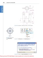
Drawing templates
Drawing templates are fi les with an extension .dwt . Templates are fi les
which have been saved with predetermined settings – such as Grid spacing
and Snap spacing. Templates can be opened from the Select template
dialog ( Fig. 1.22 ) called by clicking the New … icon in the Quick Access
Y
X
Z
Monitor screen
Fig. 1.21 A 3D model drawing showing the X, Y and Z coordinate directions
Fig. 1.22 A template selected from the Select template dialog
Introduction to AutoCAD 2011
CHAPTER 1
18
toolbar. An example of a template fi le being opened is shown in Fig. 1.22 .
In this example the template will be opened in Paper Space and is
complete with a title block and borders.
When AutoCAD 2011 is used in European countries and opened, the
acadiso.dwt template is the one most likely to appear on screen. In this
part (Part 1 – 2D Design) of this book drawings will usually be constructed
in an adaptation of the acadiso.dwt template. To adapt this template:
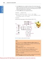
1. In the command palette enter
(type) grid followed by a right-click (or
pressing the Enter key). Then enter 10 in response to the prompt which
appears, followed by a right-click ( Fig. 1.23 ).
Fig. 1.23 Setting Grids to 10
Fig. 1.24 Setting Snap to 5
Fig. 1.25 Setting Limits to 420, 297
Fig. 1.26 Zooming to All
2. In the command palette enter snap followed by right-click . Then enter
5 followed by a right-click ( Fig. 1.24 ).
3. In the command palette enter limits
, followed by a right-click. Right-
click again. Then enter 420, 297 and right-click ( Fig. 1.25 ).
4. In the command palette enter zoom
and right-click . Then in response to the
line of prompts which appears enter a (for All) and right-click ( Fig. 1.26 ).
Introducing AutoCAD 2011
CHAPTER 1
19
6. Click the Save icon in the Quick Access toolbar ( Fig. 1.28 ). The Save
Drawing As dialog appears. In the Files of type popup list select
AutoCAD Drawing Template (*.dwt) . The templates already in
AutoCAD are displayed in the dialog. Click on acadiso.dwt , followed
by another click on the Save button.
N o t e s
1. Now when AutoCAD is opened the template saved as acadiso.dwt
automatically loads with Grid set to 10 , Snap set to 5 , Limits set to
420,297 (size of an A3 sheet in millimetres) and with the drawing
area zoomed to these limits, with Units set to 0 .
2. However, if there are multiple users by the computer, it is advisable
to save your template to another fi le name, e.g. my_template.dwt .
3. Other features will be added to the template in future chapters.
Fig. 1.27 Setting Units to 0
Fig. 1.28 Click Save
5. In the command palette enter units and right-click . The Drawing Units
dialog appears ( Fig. 1.27 ). In the Precision popup list of the Length
area of the dialog, click on 0 and then click the OK button. Note the
change in the coordinate units showing in the status bar.
Introduction to AutoCAD 2011
CHAPTER 1
20
Methods of showing entries in the command palette
Throughout the book, a tool is “ called ” usually by a click on a tool icon
in a panel – in this example entering zoom at the command line and the
following appears in the command palette:
Command :
enter
zoom
right-click
Specify corner of window, enter a scale factor
(nX or nXP), or [All/Center/Dynamic/Extents/
Previous/Scale/Window/Object] < real time > :
pick
a point on screen
Specify opposite corner:
pick
another point to
form a window
Command :
N o t e
In later examples this may be shortened to:
Command : zoom
[prompts]: following by
picking
points
Command :
N o t e s
1. In the above enter means type the given letter, word or words at the
Command: prompt.
2 . Right-click means press the Return (right) button of the mouse or
press the Return key of the keyboard.
Tools and tool icons
In AutoCAD 2011, tools are shown as names and icons in panels or in
drop-down menus. When the cursor is placed over a tool icon a description
shows with the name of the tool as shown and an explanation in diagram
form as in the example given in Fig. 1.7 (page 5).
If a small outward-facing arrow is included at the right-hand side of a tool
icon, when the cursor is placed over the icon and the pick button of the
mouse depressed and held, a fl yout appears which includes other features.
An example is given in Fig. 1.8 (page 5).
Introducing AutoCAD 2011
CHAPTER 1
21
Another AutoCAD workspace
Other workspaces can be selected as the operator wishes. One in particular
which may appeal to some operators is to click AutoCAD Classic in the
2D Drafting & Annotation popup menu ( Fig. 1.29 ).
Fig. 1.30 shows the AutoCAD Classic workspace screen.
Fig. 1.29 Selecting Classic Workspace from the popup menu
Fig. 1.30 The AutoCAD Classic workspace