Mechanism Design Enumeration of Kinematic Structures According to Function pdf
Bạn đang xem bản rút gọn của tài liệu. Xem và tải ngay bản đầy đủ của tài liệu tại đây (12.75 MB, 310 trang )
Enumeration of
Kinematic Structures
According to Function
Mechanism Design
© 2001 by CRC Press LLC
Published Titles
Entropy Generation Minimization
Adrian Bejan
Finite Element Method Using MATLAB
Young W. Kwon & Hyochoong Bang
Fundamentals of Environmental Discharge Modeling
Lorin R. Davis
Intelligent Transportation Systems: New Principles and Architectures
Sumit Ghosh & Tony Lee
Mathematical & Physical Modeling of Materials Processing Operations
Olusegun Johnson Ileghus, Manabu Iguchi & Walter E. Wahnsiedler
Mechanics of Composite Materials
Autar K. Kaw
Mechanics of Fatigue
Vladimir V. Bolotin
Mechanism Design: Enumeration of Kinematic Structures According
to Function
Lung-Wen Tsai
Nonlinear Analysis of Structures
M. Sathyamoorthy
Practical Inverse Analysis in Engineering
David M. Trujillo & Henry R. Busby
Thermodynamics for Engineers
Kau-Fui Wong
Viscoelastic Solids
Roderic S. Lakes
Forthcoming Titles
Distributed Generation: The Power Paradigm for the New Millennium
Anne-Marie Borbely & Jan F. Kreider
Engineering Experimentation
Euan Somerscales
Energy Audit of Building Systems: An Engineering Approach
Moncef Krarti
Finite Element Method Using MATLAB, 2
nd
Edition
Young W. Kwon & Hyochoong Bang
Introduction Finite Element Method
Chandrakant S. Desai & Tribikram Kundu
Mechanics of Solids & Shells
Gerald Wempner & Demosthenes Talaslidis
Principles of Solid Mechanics
Rowland Richards, Jr.
Mechanical Engineering Series
Frank Kreith - Series Editor
© 2001 by CRC Press LLC
Lung-Wen Tsai
Presidential Chair Professor
Department of Mechanical Engineering
Bourns College of Engineering
University of California, Riverside
Enumeration of
Kinematic Structures
According to Function
Mechanism Design
Boca Raton London New York Washington, D.C.
CRC Press
ON THE COVER:
A 4-speed automatic transmission. (Courtesy of General Motors, Warren, MI.)
This book contains information obtained from authentic and highly regarded sources. Reprinted material
is quoted with permission, and sources are indicated. A wide variety of references are listed. Reasonable
efforts have been made to publish reliable data and information, but the author and the publisher cannot
assume responsibility for the validity of all materials or for the consequences of their use.
Neither this book nor any part may be reproduced or transmitted in any form or by any means, electronic
or mechanical, including photocopying, microfilming, and recording, or by any information storage or
retrieval system, without prior permission in writing from the publisher.
The consent of CRC Press LLC does not extend to copying for general distribution, for promotion, for
creating new works, or for resale. Specific permission must be obtained in writing from CRC Press LLC
for such copying.
Direct all inquiries to CRC Press LLC, 2000 N.W. Corporate Blvd., Boca Raton, Florida 33431.
Trademark Notice:
Product or corporate names may be trademarks or registered trademarks, and are
used only for identification and explanation, without intent to infringe.
© 2001 by CRC Press LLC
No claim to original U.S. Government works
International Standard Book Number 0-8493-0901-8
Library of Congress Card Number 00-056415
Printed in the United States of America 1 2 3 4 5 6 7 8 9 0
Printed on acid-free paper
Library of Congress Cataloging-in-Publication Data
Tsai, Lung-Wen.
Mechanism design : enumeration of kinematic structures according to function /
Lung-Wen Tsai
p. cm (Mechanical engineering series)
Includes bibliographical references and index.
ISBN 0-8493-0901-8
1. Machinery, Kinematics of. 2. Machine design. I. Title. II. Advanced topics in
mechanical engineering series.
TJ175 .T78 2000
621.8
′11
dc21 00-056415
Preface
This textbook has evolved from class notes used for a course in systematic design
of mechanisms that the author has taught for over a decade. Although it is written
primarily for senior and first-year graduate level students in engineering, it is equally
valuable for practicing engineers, particularly for mechanism and machine designers.
Traditionally, mechanisms are created by the designer’s intuition, ingenuity, and
experience. This ad hoc approach, however, cannot ensure the identification of all
feasible design alternatives, nor does it necessarily lead to an optimum design. Two
approaches have been developed to alleviate the problem. The first involves the
development of atlases of mechanisms grouped according to function for use as a
primary source of ideas. The second makes use of a symbolic representation of
the kinematic structure and the combinatorial analysis as a tool for enumeration of
mechanisms.
This textbook introduces a systematic methodology for the creation and classifi-
cation of mechanisms. The approach is partly analytical and partly algorithmic. It
is based on the idea that, during the conceptual design phase, some of the functional
requirements of a desired mechanism can be transformed into structural characteris-
tics that can be employed for systematic enumeration of mechanisms. The kinematic
structure of a mechanism contains the essential information about which link is con-
nected to which other link by what type of joint. Using graph theory, combinatorial
analysis, and computer algorithms, kinematic structures of the same nature, i.e., the
same the number of degrees of freedom, type of motion (planar or spatial), and com-
plexity can be enumerated in an essentially systematic and unbiased manner. Then
each mechanism structure is sketched and evaluated with respect to the remaining
functional requirements. This results in a class of feasible mechanisms that can be
subject to dimensional synthesis, kinematic and dynamic analyses, design optimiza-
tion, and design detailing.
This textbook is organized as follows:
Chapter 1 provides a brief review of the design process and a systematic method-
ology for creation of mechanisms. Some terminologies related to the kinematics of
mechanism are defined. Mechanisms are classified according to the nature of motion
into planar, spherical, and spatial mechanisms.
© 2001 by CRC Press LLC
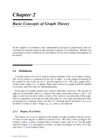
Chapter 2 is concerned withthebasic concepts of graph theory, which is essential for
structural analysis and structural synthesis of mechanisms. This material is extremely
important since the design methodology employs graphs to represent the mechanism
structure and mechanism structures are enumerated with the aid of graph theory.
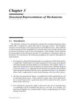
Chapter 3 introduces several methods of representation of the kinematic structure
of mechanisms. The kinematic structure, which contains the essential information
about which link is connected to which other links by what types of joint, will be used
for enumeration of mechanisms.
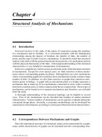
Chapter 4 examines the structural characteristics of mechanisms. The correspon-
dence between graph and mechanism is established, from which several important
mechanism structural characteristics are derived. The degrees of freedom of a mecha-
nism, the loop-mobility criterion, the concept of structural isomorphism, and various
methods of identification of structural isomorphism are described.
Chapter 5 deals with the enumeration of graphs of kinematic chains. Systematic
algorithms for the enumeration of contracted and conventional graphs are presented.
Atlases of contracted graphs and conventional graphs are developed. Using these
atlases, an enormous number of mechanisms can be developed.
Chapter 6 describes a general procedure for the enumeration and classification of
mechanisms. Planar bar linkages, geared mechanisms, cam mechanisms, spherical
mechanisms, and spatial mechanisms are enumerated and classified according to the
number of degrees of freedom, the number of independent loops, etc.
Chapter 7 covers the enumeration and classification of epicyclic gear trains (EGTs).
The structural characteristics of EGTs are identified. Various methods of enumeration
including Buchsbaum and Freudenstein’s method, the genetic graph approach, and
the parent bar linkage method are discussed. Furthermore, the theory of fundamental
circuits is introduced for the speed-ratio analysis of EGTs.
Chapters 8 and 9 offer several conceptual design examples to demonstrate the
power of the methodology. Chapter 8 concentrates on the enumeration of automotive
mechanisms, whereas Chapter 9 involves the enumeration of robotic mechanisms.
Atlases of parallel manipulators and robotic wrist mechanisms are developed.
Appendix A presents an algorithm for solving a system of m linear equations in n
unknowns. A nested do-loops algorithm serves as the basis for systematic enumera-
tion of mechanisms. Appendix B provides an atlas of contracted graphs having two to
four independent loops. Appendix C is comprised of an atlas of graphs of kinematic
chains having up to three independent loops and eight links. Appendix D offers an
atlas of planar linkages with one, two, and three degrees of freedom. Appendix E
contains an atlas of spatial one-dof, single-loop kinematic chains. Appendix F in-
cludes an atlas of epicyclic gear trains classified according to the number of degrees of
freedom, the number of independent loops, and the vertex degree listing. Appendix G
furnishes the schematic diagrams and clutching sequences of some commonly used
epicyclic transmission gear trains.
Prerequisites for readers of this textbook include the basic concepts of combinato-
rial analysis, graph theory, matrix theory, and the kinematics of mechanisms that are
usually taught at the undergraduate level. Thomas Edison said, “genius is one percent
© 2001 by CRC Press LLC
inspiration and ninety-nine percent perspiration.” Inspiration can occur more readily
when perspiration is properly directed and focused. The methodology presented in
this book is intended to help designers better organize the perspiration so that the
inspiration can take place early in the design process. For those who are willing to
try, the rewards should be well worth it.
The author wishes to express his sincere appreciation to Dr. Bernard Roth, his for-
mer Ph.D. advisor at Stanford University, and Dr. Ferdinand Freudenstein, Professor
Emeritus at Columbia University, for their lifelong advice and encouragement. A ma-
jor portion of the material presented in this textbook is derived from Dr. Freudenstein
and his former students’ research results. Others are taken from the author’s research
in collaboration with professional colleagues, Ting Liu and Roland Maki, and with his
former students, Sun-Lai Chang, Goutam Chatterjee, Dar-Zen Chen, Hsin-I Hsieh,
Chen-Chou Lin, Richard Stamper, and Farhad Tahmasebi. Their efforts are greatly
appreciated. Lastly, the author appreciates the patience and sacrifice of his family
members, Lung-Chu Tsai, Jule Ann Tsai, and David Jeanchung Tsai, over the past
few years while the textbook was being written.
Lung-Wen Tsai
Riverside, California
© 2001 by CRC Press LLC
The Author
Lung-Wen Tsai is a Presidential Chair Professor in the Department of Mechanical
Engineering at the University of California in Riverside. He obtained his B.S. degree
in mechanical engineering from the National Taiwan University in Taipei, Taiwan;
M.S. degree in engineering science from the State University of New York (SUNY)
in Buffalo, New York; and Ph.D. in mechanical engineering from Stanford University
in Stanford, California.
From 1973 to 1978, Dr. Tsai was a research and development engineer for Hewlett
Packard responsible for the design of instrumentation tape recorders and X-Y plotters.
From 1978 to 1986 he was a senior staff research engineer for General Motors and
led projects in the development of variable-stroke engine mechanisms, variable-valve
timing mechanisms, active engine balancing devices, automatic transmission mech-
anisms, and kinematics of robot manipulators. His most recent position was with the
University of Maryland in College Park from 1986 to July 2000 where he established
a nationally recognized research and education program in mechanisms and machine
theory, automotive engineering, and robot manipulators. Dr. Tsai joined the Depart-
ment of Mechanical Engineering at the University of California at Riverside in the
Fall of 2000.
Dr. Tsai is a registered professional engineer in California, a Fellow of the ASME,
and a member of the SAE. He is Chief Editor for the ASME Journal of Mechanical
Design and Chairman of the 2000 ASME International Design Engineering Technical
Conferences and the Computer in Engineering Conference. Dr. Tsai has published
one book on robot analysis (Robot Analysis: The Mechanics of Serial and Parallel
Manipulators, John Wiley & Sons, New York, 1999) and more than 100 journal and
© 2001 by CRC Press LLC
conference proceedings papers. He is the recipient of numerous awards, including the
1984 ASME Mechanism Committee best paper award, 1989 and 1991 AMR Procter &
Gamble Awards, 1985 ASME Melville Medal, 1986 GM John Campbell Award, 1988
SAE Arch Colwell Merit Award, and 1993 AMR South-Pointing-Chariot Rotating
Trophy.
© 2001 by CRC Press LLC
Contents
1 Introduction
1.1 Introduction
1.2 A Systematic Design Methodology
1.3 Links and Joints
1.4 Kinematic Chains, Mechanisms, and Machines
1.5 Kinematics of Mechanisms
1.6 Planar, Spherical, and Spatial Mechanisms
1.7 Kinematic Inversions
1.8 Summary
References
2 Basic Concepts of Graph Theory
2.1 Definitions
2.1.1 Degree of a Vertex
2.1.2 Walks and Circuits
2.1.3 Connected Graphs, Subgraphs, and Components
2.1.4 Articulation Points, Bridges, and Blocks
2.1.5 Parallel Edges, Slings, and Multigraphs
2.1.6 Directed Graph and Rooted Graph
2.1.7 Complete Graph and Bipartite
2.1.8 Graph Isomorphisms
2.2 Tree
2.3 Planar Graph
2.4 Spanning Trees and Fundamental Circuits
2.5 Euler’s Equation
2.6 Topological Characteristics of Planar Graphs
2.7 Matrix Representations of Graph
2.7.1 Adjacency Matrix
2.7.2 Incidence Matrix
2.7.3 Circuit Matrix
2.7.4 Path Matrix
2.8 Contracted Graphs
© 2001 by CRC Press LLC
2.9 Dual Graphs
2.10 Summary
References
Exercises
3 Structural Representations of Mechanisms
3.1 Introduction
3.2 Functional Schematic Representation
3.3 Structural Representation
3.4 Graph Representation
3.4.1 Advantages of Using Graph Representation
3.5 Matrix Representation
3.5.1 Adjacency Matrix
3.5.2 Incidence Matrix
3.6 Summary
References
Exercises
4 Structural Analysis of Mechanisms
4.1 Introduction
4.2 Correspondence Between Mechanisms and Graphs
4.3 Degrees of Freedom
4.4 Loop Mobility Criterion
4.5 Lower and Upper Bounds on the Number of Joints on a Link
4.6 Link Assortments
4.7 Partition of Binary Link Chains
4.8 Structural Isomorphism
4.9 Permutation Group and Group of Automorphisms
4.9.1 Group
4.9.2 Group of Automorphisms
4.10 Identification of Structural Isomorphism
4.10.1 Identification by Classification
4.10.2 Identification by Characteristic Polynomial
4.10.3 Optimum Code
4.10.4 Degree Code
4.11 Partially Locked Kinematic Chains
4.12 Summary
References
Exercises
5 Enumeration of Graphs of Kinematic Chains
5.1 Introduction
5.2 Enumeration of Contracted Graphs
5.3 Enumeration of Conventional Graphs
5.4 Atlas of Graphs of Kinematic Chains
© 2001 by CRC Press LLC
5.5 Summary
References
Exercises
6 Classification of Mechanisms
6.1 Introduction
6.2 Planar Mechanisms
6.2.1 Planar Linkages
6.2.2 Planar Geared Mechanisms
6.2.3 Planar Cam Mechanisms
6.3 Spherical Mechanisms
6.4 Spatial Mechanisms
6.4.1 Spatial One-dof Mechanisms
6.4.2 Spatial Multi-dof, Multiple-Loop Mechanisms
6.5 Summary
References
Exercises
7 Epicyclic Gear Trains
7.1 Introduction
7.2 Structural Characteristics
7.3 Buchsbaum–Freudenstein Method
7.4 Genetic Graph Approach
7.5 Parent Bar Linkage Method
7.6 Mechanism Pseudoisomorphisms
7.7 Atlas of Epicyclic Gear Trains
7.7.1 One-dof Epicyclic Gear Trains
7.7.2 Two-dof Epicyclic Gear Trains
7.7.3 Three-dof Epicyclic Gear Trains
7.8 Kinematics of Epicyclic Gear Trains
7.8.1 Fundamental Circuit Equations
7.8.2 Examples
7.9 Summary
References
Exercises
8 Automotive Mechanisms
8.1 Introduction
8.2 Variable-Stroke Engine Mechanisms
8.2.1 Functional Requirements
8.2.2 Structural Characteristics
8.2.3 Enumeration of VS-Engine Mechanisms
8.3 Constant-Velocity Shaft Couplings
8.3.1 Functional Requirement
8.3.2 Structural Characteristics
© 2001 by CRC Press LLC
8.3.3 Enumeration of C-V Shaft Couplings
8.4 Automatic Transmission Mechanisms
8.4.1 Functional Requirements
8.4.2 Structural Characteristics
8.4.3 Enumeration of Epicyclic Gear Mechanisms
8.5 Canonical Graph Representation of EGMs
8.5.1 Structural Characteristics of Canonical Graphs
8.5.2 Enumeration of Canonical Graphs
8.5.3 Identification of Fundamental Circuits
8.5.4 Detection of Transfer Vertices
8.6 Atlas of Epicyclic Gear Transmission Mechanisms
8.7 Summary
References
Exercises
9 Robotic Mechanisms
9.1 Introduction
9.2 Parallel Manipulators
9.2.1 Functional Requirements
9.2.2 Structural Characteristics
9.2.3 Enumeration of Planar Parallel Manipulators
9.2.4 Enumeration of Spherical Parallel Manipulators
9.2.5 Enumeration of Spatial Parallel Manipulators
9.3 Robotic Wrist Mechanisms
9.3.1 Functional Requirements
9.3.2 Structural Characteristics
9.3.3 Enumeration of Three-dof Wrist Mechanisms
9.4 Summary
References
Exercises
A Solving m Linear Equations in n Unknowns
A.1 Solving One Equation in n Unknowns
A.2 Solving m Equations in n Unknowns
References
B Atlas of Contracted Graphs
C Atlas of Graphs of Kinematic Chains
D Atlas of Planar Bar Linkages
E Atlas of Spatial One-dof Kinematic Chains
F Atlas of Epicyclic Gear Trains
G Atlas of Epicyclic Gear Transmission Mechanisms
© 2001 by CRC Press LLC
Chapter 1
Introduction
1.1 Introduction
Design is the creation of synthesized solutions in the form of products or systems
that satisfy customer’s requirements [9, 25, 30, 34]. When we are given a design
problem, we try to make the best use of our knowledge and the available information
to understand the problem and generate as many feasible solutions as possible. Then,
we evaluate these concepts against the customer’s requirements and select a most
promising concept for design analysis and design optimization. We may think of the
design as a mapping of the customer’s requirements into a physical embodiment. The
better we understand the problem associated with the customer’s requirements, the
better design we can achieve.
The design process can be logically divided into three interrelated phases: (1) prod-
uct specification and planning phase, (2) conceptual design phase, and (3) product
design phase. During the product specification and planning phase, we identify the
customer’s requirements and translate them into engineering specifications in terms
of the functional requirements and the time and money available for the development,
and plan the project accordingly. In the conceptual design phase, we generate as
many design alternatives as possible, evaluate them against the functional require-
ments, and select the most promising concept for design detailing. A rough idea of
how the product will function and what it will look like is developed. In the product
design phase, we perform a thorough design analysis, design optimization, and simu-
lation of the selected concept. Function, shape, material, and production methods are
considered. Several prototype machines are constructed and tested to demonstrate
the concept. Finally, an engineering documentation is produced and the design goes
into the production phase. However, if the concept selected for the product design
is shown to be impractical, it may be necessary to go back to the conceptual design
phase to select an alternate concept or to generate additional concepts. In this re-
gard, it may be necessary to reevaluate the engineering specifications developed in
the product specification and planning phase.
Design is a continuous process of refining customer requirements into a final prod-
uct. The process is iterative in nature and the solutions are usually not unique. It
© 2001 by CRC Press LLC
involves a process of decision making. A talented and experienced engineer can
often make sound engineering decisions to arrive at a fine product. Although the
third phase is usually the most time consuming phase, most of the manufacturing cost
of a product is committed by the end of conceptual design phase. According to a
survey, 75% of the manufacturing cost of a typical product is committed during the
first two phases. Decisions made after the conceptual design phase only have 25%
influence on the manufacturing cost. Therefore, it is critical that we pay sufficient
attention to the product specification and conceptual design phases. One approach
for the generation of concepts is to identify the overall function of a device based
on the customer’s requirements, and decompose it into subfunctions. Then, various
concepts that satisfy each of the functions are generated and combined into a complete
design. Techniques for generation of concepts include literature and patent search,
imitation of natural systems, analysis of competitor products, brainstorming, etc.
In this text, we concentrate on the conceptual design phase of mechanisms. The
conceptual design is traditionally accomplished by the designer’s intuition, ingenu-
ity, and experience. An alternate approach is to generate an atlas of mechanisms
classified according to functional characteristics for use as the sources of ideas for
mechanism designers [1, 17, 19, 20, 21, 24]. This approach, however, cannot en-
sure the identification of all feasible mechanisms, nor does it necessarily lead to an
optimum design.
Recently, a new approach based on an abstract representation of the kinematic
structure, which is somewhat similar to the symbolic representation of chemical
compounds, has evolved. The kinematic structure contains the essential information
about which link is connected to which other links by what types of joint. It can be
conveniently represented by a graph and the graph can be enumerated systematically
using combinatorial analysis and computer algorithms [6, 7, 8, 10, 13, 15, 35]. This
approach, which appears to be promising, is the basis of this text.
In the following, we briefly introduce the methodology and review some of the
fundamentals of the kinematics of mechanisms to facilitate the development of the
methodology.
1.2 A Systematic Design Methodology
The methodology is based on the application of graph theory and combinatorial
analysis. First, the functional requirements of a class of mechanisms are identified.
Then, kinematic structures of the same nature are enumerated systematically using
graph theory and combinatorial analysis. Third, each kinematic structure is sketched
and qualitatively evaluated according to its potential in meeting the functional re-
quirements. Finally, a promising concept is chosen for dimensional synthesis, design
optimization, computer simulation, and prototype demonstration. The process may
be iterated several times until a final product is achieved.
© 2001 by CRC Press LLC
We summarize the methodology as follows:
1. Identify the functional requirements, based on customers’ requirements, of a
class of mechanisms of interest.
2. Determine the nature of motion (i.e., planar, spherical, or spatial mechanism),
degrees of freedom (dof), type, and complexity of the mechanisms.
3. Identify the structural characteristics associated with some of the functional
requirements.
4. Enumerate all possible kinematic structures that satisfy the structural charac-
teristics using graph theory and combinatorial analysis.
5. Sketch the corresponding mechanisms and evaluate each of them qualitatively
in terms of its capability in satisfying the remaining functional requirements.
This results in a set of feasible mechanisms.
6. Select a most promising mechanism for dimensional synthesis, design opti-
mization, computer simulation, prototype demonstration, and documentation.
7. Enter the production phase.
We note that the methodology consists of two engines: a generator and an evaluator
asshowninFigure1.1.Someofthefunctionalrequirementsaretransformedintothe
structural characteristics and incorporated in the generator as rules of enumeration.
The generator enumerates all possible solutions using graph theory and combinatorial
analysis. The remaining functional requirements are incorporated in the evaluator
as evaluation criteria for the selection of concepts [3]. This results in a class of
feasible mechanisms. Finally, a most promising candidate is chosen for the product
design. The process may be iterated several times until a final product is achieved.
This methodology has been successfully applied in the structure synthesis of planar
linkages, epicyclic gear trains, automotive transmission mechanisms, variable-stroke
engine mechanisms, robotic wrist mechanisms, etc. [2, 3, 7, 12, 14, 22, 29, 31].
How many of the functional requirements should be incorporated in the generator is
a matter of engineering decision. The more functional requirements that are translated
into structural characteristics and incorporated in the generator, the less work is needed
from the evaluator. However, this may make the generator too complex to develop.
Generally, if a functional requirement can be written in a mathematical form, it should
be included in the generator. The method presented in this text is similar in a way to
that described in [36].
1.3 Links and Joints
We define a material body as a rigid body if the distance between any two points
of the body remains constant. In reality, rigid bodies do not exist, since all known
© 2001 by CRC Press LLC
FIGURE 1.1
A systematic mechanism design methodology.
materials deform under stress. However, we may consider a body as rigid if its
deformation under stress is negligibly small. The use of rigid bodies makes the
study of kinematics of mechanisms easier. However, for light-weight and high-speed
mechanisms, the elastic effects of a material body may become significant and must
be taken into consideration. In this text, unless otherwise stated, we shall treat all
bodies as being rigid. A rigid body may be considered as being infinitely large for
study of the kinematics of mechanisms.
The individual rigid bodies making up a machine or mechanism are called members
or links. For convenience, certain nonrigid bodies such as chains, cables, or belts,
which momentarily serve the same function as rigid bodies, may also be considered
© 2001 by CRC Press LLC
as links. From the kinematics point of view, two or more members connected together
such that no relative motion can occur between them will be considered as one link.
The links in a machine or mechanism are connected in pairs. The connection
between two links is called a joint. A joint physically adds some constraint(s) to the
relative motion between the two members. The kind of relative motion permitted by
a joint is governed by the form of the surfaces of contact between the two members.
The surface of contact of a link is called a pair element. Two such paired elements
form a kinematic pair.
We classify kinematic pairs into lower pairs and higher pairs according to the
contact between the paired elements. A kinematic pair is called a lower pair if one
pair of the element not only forms the envelope of the other, but also encloses it. The
forms of the lower pair elements are geometrically identical, one being solid while
the other is hollow. Lower pairs have surface contact. On the other hand, if the pair
elements do not enclose each other, we call the pair a higher pair. Higher pairs have
line or point contact between the element surfaces.
There are six lower pairs and two higher pairs that are frequently used in mecha-
nismsasshowninFigure1.2.Wedescribeeachofthembrieflyasfollows.
A revolute joint, R, permits two paired elements to rotate with respect to one another
about an axis that is defined by the geometry of the joint. Therefore, the revolute joint
is a one degree-of-freedom (dof) joint; that is, it imposes five constraints on the paired
elements. The revolute joint is sometimes called a turning pair, a hinge, or a pin joint.
A prismatic joint, P , allows two paired elements to slide with respect to each other
along an axis defined by the geometry of the joint. Similar to a revolute joint, the
prismatic joint is a one-dof joint. It imposes five constraints on the paired elements.
The prismatic joint is also called a sliding pair.
A cylindric joint, C, permits a rotation about and an independent translation along
an axis defined by the geometry of the joint. Therefore, the cylindric joint is a two-
dof joint. It imposes four constraints on the paired elements. A cylindric joint is
kinematically equivalent to a revolute joint in series with a prismatic joint with their
joint axes parallel to or coincident with each other.
A helical joint, H , allows two paired elements to rotate about and translate along
an axis defined by the geometry of the joint. However, the translation is related to
the rotation by the pitch of the joint. Hence, the helical joint is a one-dof joint. It
imposes five constraints on the paired elements. The helical joint is sometimes called
a screw pair.
A spherical joint, S, allows one element to rotate freely with respect to the other
about the center of a sphere. It is a ball-and-socket joint that permits no translations
between the paired elements. Hence, the spherical joint is a three-dof joint; that is, it
imposes three constraints on the paired elements. A spherical joint is kinematically
equivalent to three intersecting revolute joints.
A plane pair, E, permits two translational degrees of freedom on a plane and a
rotational degree of freedom about an axis that is normal to the plane of contact.
Hence, the plane pair is a three-dof joint; that is, it imposes three constraints on the
paired elements.
© 2001 by CRC Press LLC
FIGURE 1.2
Eight frequently used kinematic pairs.
A gear pair, G, permits one gear to roll and slide with respect to the other at the
point of contact between two meshing teeth. In addition, the motion space of each
gear is constrained on a plane perpendicular to its central axis of rotation. Therefore,
the gear pair is a two-dof joint. It imposes four constraints on the paired elements.
The meshing surfaces of a gear pair must satisfy the law of gearing and the diametric
pitchofapairofgearsmustbeequaltooneanother[23].Figure1.3showsaspurgear
pair manufactured by Boston Gear. When the pitch diameter of one gear becomes
© 2001 by CRC Press LLC
infinitely large, it becomes a rack-and-pinion gear pair. A bevel gear pair may be
employed to change the direction of rotation.
FIGURE 1.3
A spur gear pair. (Courtesy of Boston Gear, Boston, MA.)
Similar to a gear pair, a cam pair, C
p
, allows a follower to roll and slide with respect
to the cam at the point of contact. However, the two mating surfaces of a cam pair
can virtually take any desired form [18]. A spring is incorporated to keep the two
paired elements in contact. Hence, the cam pair is also a two-dof joint.
Further, there is a commonly used composite joint called the universal joint as
showninFigure1.4.Auniversaljointismadeupoftwointersectingrevolutejoints.
Therefore, it is a two-dof joint. The universal joint is sometimes referred to as the
Hooke joint or Cardan joint. Neither Hooke nor Cardan invented the universal joint.
The reason we associate Hooke’s name with the joint is that he put it in use in the
17th century.
Revolute, prismatic, cylindric, helical, spherical, and plane pairs are lower pairs.
Gearandcampairsarehigherpairs.Table1.1summarizesthedegreesoffreedom
and the types of motion associated with each of the kinematic pairs.
A higher pair can often be replaced by a combination of two lower pairs in order to
reduce stress concentration and wear at the point of contact. For example, a cylindric
rodridinginarectangularguideasshowninFigure1.5aisnotpractical.Thesame
constraint can be achieved by adding an intermediate link and connecting them with
© 2001 by CRC Press LLC
FIGURE 1.4
Universal joint. (Courtesy of Boston Gear, Boston, MA.)
Table 1.1 Eight Frequently Used Kinematic Pairs.
Kinematic Pair Symbol Joint DOF Rotational Translational
Revolute R 11 0
Prismatic
P 10 1
Cylindric
C 21 1
Helical
H 1 1 coupled
Spherical
S
33 0
Plane
E 31 2
Gear Pair
G
21 1
Cam Pair
C
p
21 1
acombinationofrevoluteandprismaticjointsasshowninFigure1.5b.Hence,the
two-dof motion permitted by the higher pair is obtained by two lower pairs.
A link is called a binary link if it is connected to only two other links, a ternary
link if it is connected to three other links, a quaternary link if it is connected to four
other links, and so on. A joint is called a binary joint, if it connects only two links,
and a multiple joint, if it connects more than two links.
© 2001 by CRC Press LLC
FIGURE 1.5
Substitution of a higher pair with two lower pairs.
1.4 Kinematic Chains, Mechanisms, and Machines
A kinematic chain is an assemblage of links, or rigid bodies, that are connected
by joints. If every link in a kinematic chain is connected to every other link by one
and only one path, it is called an open-loop chain. On the other hand, if every link is
connected to every other link by at least two distinct paths, the kinematic chain forms
one or more closed loops and is called a closed-loop chain. Clearly, it is possible
for a kinematic chain to contain both closed- and open-loop chains. We call such a
kinematic chain a hybrid kinematic chain.
When one of the links in a kinematic chain is fixed to the ground or base, it is called
a mechanism. The link that is fixed to the base is called the fixed link. As the input
link(s) move with respect to the base, all other links perform constrained motions.
Thus, a mechanism is a device that transforms motion and/or torque from one or more
linkstotheothers.Forexample,Figure1.6showsacrank-and-slidermechanismthat
transforms a continuous rotation of the crank into a reciprocal motion of the slider
and vice versa.
When one or more mechanisms are assembled together with other hydraulic, pneu-
matic, and electrical components such that mechanical forces of nature can be com-
pelled to do work, we call such an assembly a machine. That is, a machine is an
assemblage of several components for the purpose of transforming external energy
into useful work.
Although the terms mechanism and machine are often used synonymously, in
realitythereisadefinitedifference.Figure1.7showsa6-axismillingmachine
produced by Giddings & Lewis Machine Tools. The basic mechanism of the machine
consists of a moving platform, a fixed base, and six supporting limbs. Each limb
is made up of two members that are connected to each other by a prismatic joint.
The upper end of each limb is connected to the moving platform by a universal
joint, whereas the lower end is connected to the base by a spherical joint. The
motion of the prismatic joint is controlled by a motor-driven ball screw. Together
it forms a parallel manipulator generally known as the Stewart-Gough manipulator.
© 2001 by CRC Press LLC
FIGURE 1.6
Crank-and-slider mechanism.
The platform itself is a mechanism and not a machine. When actuators, sensors,
spindle, loading/unloading mechanism, and a controller are incorporated, it becomes
a machine. We observe that a machine may consist of several mechanisms. However,
a mechanism is not necessarily a machine since it may be part of a machine to serve
as a motion transformation device.
FIGURE 1.7
VARIAX
®
machining center. (Courtesy of Giddings & Lewis Machine Tools,
Fond Du Lac, WI.)
© 2001 by CRC Press LLC
1.5 Kinematics of Mechanisms
A rigid body is said to be under motion when it is instantaneously changing its
position and/or orientation. Since the change of position can only be observed with
respect to another body, the motion of a rigid body is a relative measure. Kinematics
of a mechanism is the study of relative motion among the various links of a mechanism
or machine by neglecting the inertia effects and the forces that cause the motion. In
studying the kinematics of a mechanism, the motion of a link is often measured with
respect to a fixed link or a reference frame, which may not necessarily be at rest.
There are two branches of kinematics known as kinematic analysis and kinematic
synthesis.
Kinematic analysis is the study of relative motions associated with the links of
a mechanism or machine and is a critical step toward proper design of a mecha-
nism. Specifically, given a mechanism and the motion of its input link(s), the relative
displacement, velocity, acceleration, etc., of the other links are to be found. These
characteristics can be derived by considering the constraints imposed by the joints.
The problem can be formulated by the graphical, vector algebra, matrix, or other
mathematical methods [11, 23].
Kinematic synthesis is the reverse problem of kinematic analysis. In this case,
the designer is challenged to devise a new mechanism that satisfies certain desired
motion characteristics of an output link. The kinematic synthesis problem can be
further divided into three interrelated phases:
1. Type synthesis refers to the selection of a specific type of mechanism for prod-
uct development. During the conceptual design phase, the designer considers
as many types of mechanism as possible and decides what type has the best
potential of meeting the design objectives. The type of mechanism — cam,
linkage, gear train, and so on — is determined. The selection depends to a great
extent on the functional requirements of a machine and other considerations
such as materials, manufacturing processes, and cost.
2. Number synthesis deals with the determination of the number of links, type
of joint, and number of joints needed to achieve a given number of degrees
of freedom of a desired mechanism. During this phase of study, the designer
makes sure that a mechanism has the correct number of links that are connected
with proper types of joints to ensure mobility. Number synthesis also involves
the enumeration of all feasible kinematic structures or linkage topologies for
a given number of degrees of freedom, number of links, and type of joints.
For this reason it is sometimes called structure synthesis or topological synthe-
sis. Various methodologies have been developed for systematic enumeration
of kinematic structures [13]. A thorough understanding of the structural char-
acteristics of a given type of mechanism is critical for the development of an
efficient algorithm.
© 2001 by CRC Press LLC
3. Dimensional synthesis deals with the determination of the dimensions or pro-
portions of the links of a mechanism. Laying out a cam profile to meet a desired
lift specification is a dimensional synthesis problem. Determination of the cen-
ter distance between two pivots of a link in a bar-linkage is also a dimensional
synthesis problem. Both geometric and analytical methods of synthesis may be
used to perform dimensional synthesis. The Burmester theorem can be applied
in the dimensional synthesis of planar linkages [16]. Recently, the theorem
was extended to that of spatial linkages [4, 5, 26, 27, 28, 32, 33]. Typical
problems in dimensional synthesis include function generation, coupler-point
curve synthesis, and rigid body guidance.
Type synthesis involves design factors such as materials, manufacturing processes,
reliability consideration, and cost issues that are usually determined at the initial phase
of the design process. In this text, we are concerned primarily with the structure
synthesis of mechanisms.
1.6 Planar, Spherical, and Spatial Mechanisms
Mechanisms can be classified into three types according to their nature of motion.
A rigid body is said to be under planar motion if the motion of all particles in the
rigid body are constrained in parallel planes. A planar mechanism is one in which all
the moving links perform parallel planar motions. For a planar mechanism, the loci
of all points in all links can be conveniently drawn in one plane. Planar mechanisms
that utilize only lower-pair joints are called planar linkages. Revolute and prismatic
joints are the only allowable lower pairs in planar linkages. Furthermore, the axis of a
revolute joint must be perpendicular to the plane of motion, whereas the direction of
translation of a prismatic joint must be parallel to the plane of motion. For examples,
Figures1.8,1.9,and1.10showaplanarfour-barlinkage,aplanarplatecam-and-
follower mechanism, and a planar spur-gear drive, respectively.
A rigid body is said to be performing a spherical motion if the motions of all
particles in the rigid body are confined on concentric spherical surfaces. When a
rigid body performs a spherical motion, one of its points remains stationary. A
spherical mechanism is one in which all the moving links perform concentric spherical
motions about a common stationary point, called the spherical center. In a spherical
mechanism, the motions of all particles can be conveniently described by their radial
projections on the surface of a unit sphere. The revolute joint is the only permissible
lower-pair joint for constructing spherical mechanisms. In addition, all the joint axes
must intersect at a common point.
Figure1.11showsasphericalfour-barlinkageknownasthe universal joint.
The universal joint is used to transmit motion between two intersecting but non-
collinear shafts. However, it is not a constant-velocity coupling device. In rear wheel
drive vehicles, two Hooke joints are connected in series to achieve constant-velocity
© 2001 by CRC Press LLC