the mems handbook mems applications 2nd ed m gad el hak doc
Bạn đang xem bản rút gọn của tài liệu. Xem và tải ngay bản đầy đủ của tài liệu tại đây (26.07 MB, 547 trang )
MEMS
Applications
© 2006 by Taylor & Francis Group, LLC
Mechanical Engineering Series
Frank Kreith and Roop Mahajan - Series Editors
Published Titles
Distributed Generation: The Power Paradigm for the New Millennium
Anne-Marie Borbely & Jan F. Kreider
Elastoplasticity Theory
Vlado A. Lubarda
Energy Audit of Building Systems: An Engineering Approach
Moncef Krarti
Engineering Experimentation
Euan Somerscales
Entropy Generation Minimization
Adrian Bejan
Finite Element Method Using MATLAB, 2
nd
Edition
Young W. Kwon & Hyochoong Bang
Fluid Power Circuits and Controls: Fundamentals and Applications
John S. Cundiff
Fundamentals of Environmental Discharge Modeling
Lorin R. Davis
Heat Transfer in Single and Multiphase Systems
Greg F. Naterer
Introductory Finite Element Method
Chandrakant S. Desai & Tribikram Kundu
Intelligent Transportation Systems: New Principles and Architectures
Sumit Ghosh & Tony Lee
Mathematical & Physical Modeling of Materials Processing Operations
Olusegun Johnson Ilegbusi, Manabu Iguchi & Walter E. Wahnsiedler
Mechanics of Composite Materials
Autar K. Kaw
Mechanics of Fatigue
Vladimir V. Bolotin
Mechanics of Solids and Shells: Theories and Approximations
Gerald Wempner & Demosthenes Talaslidis
Mechanism Design: Enumeration of Kinematic Structures According
to Function
Lung-Wen Tsai
The MEMS Handbook, Second Edition
MEMS: Introduction and Fundamentals
MEMS: Design and Fabrication
MEMS: Applications
Mohamed Gad-el-Hak
Nonlinear Analysis of Structures
M. Sathyamoorthy
Practical Inverse Analysis in Engineering
David M. Trujillo & Henry R. Busby
Pressure Vessels: Design and Practice
Somnath Chattopadhyay
Principles of Solid Mechanics
Rowland Richards, Jr.
Thermodynamics for Engineers
Kau-Fui Wong
Vibration and Shock Handbook
Clarence W. de Silva
Viscoelastic Solids
Roderic S. Lakes
© 2006 by Taylor & Francis Group, LLC
A CRC title, part of the Taylor & Francis imprint, a member of the
Taylor & Francis Group, the academic division of T&F Informa plc.
Boca Raton London New York
Edited by
Mohamed Gad-el-Hak
The MEMS Handbook
Second Edition
MEMS
Applications
© 2006 by Taylor & Francis Group, LLC
F
oreground: A 24-layer rotary varactor fabricated in nickel using the Electrochemical Fabrication (EFAB®) technology.
See Chapter 6, MEMS: Design and Fabrication, for details of the EFAB® technology. Scanning electron micrograph courtesy
of Adam L. Cohen, Microfabrica Incorporated (www.microfabrica.com), U.S.A.
Background: A two-layer surface macromachined, vibrating gyroscope. The overall size of the integrated circuitry is 4.5
× 4.5 mm. Sandia National Laboratories' emblem in the lower right-hand corner is 700 microns wide. The four silver
re
ctangles in the center are the gyroscope's proof masses, each 240 × 310 × 2.25 microns. See Chapter 4, MEMS: Applications
(0-8493-9139-3), for design and fabrication details. Photograph courtesy of Andrew D. Oliver, Sandia National Laboratories.
Publis
hed in 2006 by
CRC Press
T
aylor & Francis Group
60
00 Broken Sound Parkway NW, Suite 300
Boca Raton, FL 33487-2742
© 2006 by Taylor & Francis Group, LLC
CRC Press is an imprint of Taylor & Francis Group
No claim to original U.S. Government works
Printed in the United States of America on acid-free paper
10 9 8 7 6 5 4 3 2 1
International Standard Book Number-10: 0-8493-9139-3 (Hardcover)
International Standard Book Number-13: 978-0-8493-9139-2 (Hardcover)
Library of Congress Card Number 2005051409
This book contains information obtained from authentic and highly regarded sources. Reprinted material is quoted with
permission, and sources are indicated. A wide variety of references are listed. Reasonable efforts have been made to publish
reliable data and information, but the author and the publisher cannot assume responsibility for the validity of all materials
or for the consequences of their use.
No part of this book may be reprinted, reproduced, transmitted, or utilized in any form by any electronic, mechanical, or
other means, now known or hereafter invented, including photocopying, microfilming, and recording, or in any information
storage or retrieval system, without written permission from the publishers.
For permission to photocopy or use material electronically from this work, please access www.copyright.com
( or contact the Copyright Clearance Center, Inc. (CCC) 222 Rosewood Drive, Danvers, MA
01923, 978-750-8400. CCC is a not-for-profit organization that provides licenses and registration for a variety of users. For
organizations that have been granted a photocopy license by the CCC, a separate system of payment has been arranged.
Trademark Notice: Product or corporate names may be trademarks or registered trademarks, and are used only for
identification and explanation without intent to infringe.
Library of Congress Cataloging-in-Publication Data
MEMS : applications / edited by Mohamed Gad-el-Hak.
p. cm. (Mechanical engineering series)
Includes bibliographical references and index.
ISBN 0-8493-9139-3 (alk. paper)
1. Microelectromechanical systems. 2. Detectors. 3. Microactuators. 4. Robots. I. Gad-el-Hak, Mohamed,
1945- II. Mechanical engineering series (Boca Raton Fla.)
TK7875.M423 2005
621.381 dc22 2005051409
Visit the Taylor & Francis Web site at
and the CRC Press Web site at
Taylor & Francis Group
is the Academic Division of Informa plc.
© 2006 by Taylor & Francis Group, LLC
v
Preface
In a little time I felt something alive moving on my left leg, which advancing gently forward over my
breast, came almost up to my chin; when bending my eyes downward as much as I could, I perceived
it to be a human creature not six inches high, with a bow and arrow in his hands, and a quiver at his
back. … I had the fortune to break the strings, and wrench out the pegs that fastened my left arm to the
ground; for, by lifting it up to my face, I discovered the methods they had taken to bind me, and at the
same time with a violent pull, which gave me excessive pain, I a little loosened the strings that tied down
my hair on the left side, so that I was just able to turn my head about two inches. … These people are
most excellent mathematicians, and arrived to a great perfection in mechanics by the countenance and
encouragement of the emperor, who is a renowned patron of learning. This prince has several machines
fixed on wheels, for the carriage of trees and other great weights.
(From Gulliver’s Travels—A Voyage to Lilliput, by Jonathan Swift, 1726.)
In the Nevada desert, an experiment has gone horribly wrong. A cloud of nanoparticles — micro-robots —
has escaped from the laboratory. This cloud is self-sustaining and self-reproducing. It is intelligent and
learns from experience. For all practical purposes, it is alive.
It has been programmed as a predator. It is evolving swiftly, becoming more deadly with each passing
hour.
Every attempt to destroy it has failed.
And we are the prey.
(From Michael Crichton’s techno-thriller Prey, HarperCollins Publishers, 2002.)
Almost three centuries apart, the imaginative novelists quoted above contemplated the astonishing, at
times frightening possibilities of living beings much bigger or much smaller than us. In 1959, the physicist
Richard Feynman envisioned the fabrication of machines much smaller than their makers. The length scale
of man, at slightly more than 10
0
m, amazingly fits right in the middle of the smallest subatomic particle,
which is approximately 10
Ϫ26
m, and the extent of the observable universe, which is of the order of 10
26
m.
Toolmaking has always differentiated our species from all others on Earth. Close to 400,000 years ago,
archaic Homo sapiens carved aerodynamically correct wooden spears. Man builds things consistent with
his size, typically in the range of two orders of magnitude larger or smaller than himself. But humans have
always striven to explore, build, and control the extremes of length and time scales. In the voyages to
Lilliput and Brobdingnag in Gulliver’s Travels, Jonathan Swift speculates on the remarkable possibilities
which diminution or magnification of physical dimensions provides. The Great Pyramid of Khufu was
originally 147m high when completed around 2600 B.C., while the Empire State Building constructed in
1931 is presently 449 m high. At the other end of the spectrum of manmade artifacts, a dime is slightly
less than 2 cm in diameter. Watchmakers have practiced the art of miniaturization since the 13th century.
The invention of the microscope in the 17th century opened the way for direct observation of microbes
and plant and animal cells. Smaller things were manmade in the latter half of the 20th century. The
© 2006 by Taylor & Francis Group, LLC
transistor in today’s integrated circuits has a size of 0.18 micron in production and approaches 10
nanometers in research laboratories.
Microelectromechanical systems (MEMS) refer to devices that have characteristic length of less than
1 mm but more than 1 micron, that combine electrical and mechanical components, and that are fabricated
using integrated circuit batch-processing technologies. Current manufacturing techniques for MEMS
include surface silicon micromachining; bulk silicon micromachining; lithography, electrodeposition,
and plastic molding; and electrodischarge machining. The multidisciplinary field has witnessed explosive
growth during the last decade and the technology is progressing at a rate that far exceeds that of our
understanding of the physics involved. Electrostatic, magnetic, electromagnetic, pneumatic and thermal
actuators, motors, valves, gears, cantilevers, diaphragms, and tweezers of less than 100 micron size have
been fabricated. These have been used as sensors for pressure, temperature, mass flow, velocity, sound and
chemical composition, as actuators for linear and angular motions, and as simple components for com-
plex systems such as robots, lab-on-a-chip, micro heat engines and micro heat pumps. The lab-on-a-chip
in particular is promising to automate biology and chemistry to the same extent the integrated circuit has
allowed large-scale automation of computation. Global funding for micro- and nanotechnology research
and development quintupled from $432 million in 1997 to $2.2 billion in 2002. In 2004, the U.S. National
Nanotechnology Initiative had a budget of close to $1 billion, and the worldwide investment in nanotech-
nology exceeded $3.5 billion. In 10 to 15 years, it is estimated that micro- and nanotechnology markets
will represent $340 billion per year in materials, $300 billion per year in electronics, and $180 billion per
year in pharmaceuticals.
The three-book MEMS set covers several aspects of microelectromechanical systems, or more broadly,
the art and science of electromechanical miniaturization. MEMS design, fabrication, and application as
well as the physical modeling of their materials, transport phenomena, and operations are all discussed.
Chapters on the electrical, structural, fluidic, transport and control aspects of MEMS are included in the
books. Other chapters cover existing and potential applications of microdevices in a variety of fields,
including instrumentation and distributed control. Up-to-date new chapters in the areas of microscale
hydrodynamics, lattice Boltzmann simulations, polymeric-based sensors and actuators, diagnostic tools,
microactuators, nonlinear electrokinetic devices, and molecular self-assembly are included in the three
books constituting the second edition of The MEMS Handbook. The 16 chapters in MEMS: Introduction
and Fundamentals provide background and physical considerations, the 14 chapters in MEMS: Design
and Fabrication discuss the design and fabrication of microdevices, and the 15 chapters in MEMS:
Applications review some of the applications of microsensors and microactuators.
There are a total of 45 chapters written by the world’s foremost authorities in this multidisciplinary
subject. The 71 contributing authors come from Canada, China (Hong Kong), India, Israel, Italy, Korea,
Sweden, Taiwan, and the United States, and are affiliated with academia, government, and industry. Without
compromising rigorousness, the present text is designed for maximum readability by a broad audience
having engineering or science background. As expected when several authors are involved, and despite
the editor’s best effort, the chapters of each book vary in length, depth, breadth, and writing style. These
books should be useful as references to scientists and engineers already experienced in the field or
as primers to researchers and graduate students just getting started in the art and science of electro-
mechanical miniaturization. The Editor-in-Chief is very grateful to all the contributing authors for their
dedication to this endeavor and selfless, generous giving of their time with no material reward other than
the knowledge that their hard work may one day make the difference in someone else’s life. The talent,
enthusiasm, and indefatigability of Taylor & Francis Group’s Cindy Renee Carelli (acquisition editor),
Jessica Vakili (production coordinator), N. S. Pandian and the rest of the editorial team at Macmillan
India Limited, Mimi Williams and Tao Woolfe (project editors) were highly contagious and percolated
throughout the entire endeavor.
Mohamed Gad-el-Hak
vi Preface
© 2006 by Taylor & Francis Group, LLC
vii
Editor-in-Chief
Mohamed Gad-el-Hak received his B.Sc. (summa cum laude) in mechani-
cal engineering from Ain Shams University in 1966 and his Ph.D. in fluid
mechanics from the Johns Hopkins University in 1973, where he worked with
Professor Stanley Corrsin. Gad-el-Hak has since taught and conducted research
at the University of Southern California, University of Virginia, University of
Notre Dame, Institut National Polytechnique de Grenoble, Université de Poitiers,
Friedrich-Alexander-Universität Erlangen-Nürnberg, Technische Universität
München, and Technische Universität Berlin, and has lectured extensively at sem-
inars in the United States and overseas. Dr. Gad-el-Hak is currently the Inez
Caudill Eminent Professor of Biomedical Engineering and chair of mechanical
engineering at Virginia Commonwealth University in Richmond. Prior to his
Notre Dame appointment as professor of aerospace and mechanical engineering, Gad-el-Hak was senior
research scientist and program manager at Flow Research Company in Seattle, Washington, where he
managed a variety of aerodynamic and hydrodynamic research projects.
Professor Gad-el-Hak is world renowned for advancing several novel diagnostic tools for turbulent
flows, including the laser-induced fluorescence (LIF) technique for flow visualization; for discovering the
efficient mechanism via which a turbulent region rapidly grows by destabilizing a surrounding laminar
flow; for conducting the seminal experiments which detailed the fluid–compliant surface interactions in
turbulent boundary layers; for introducing the concept of targeted control to achieve drag reduction, lift
enhancement and mixing augmentation in wall-bounded flows; and for developing a novel viscous pump
suited for microelectromechanical systems (MEMS) applications. Gad-el-Hak’s work on Reynolds num-
ber effects in turbulent boundary layers, published in 1994, marked a significant paradigm shift in the
subject. His 1999 paper on the fluid mechanics of microdevices established the fledgling field on firm
physical grounds and is one of the most cited articles of the 1990s.
Gad-el-Hak holds two patents: one for a drag-reducing method for airplanes and underwater vehicles and
the other for a lift-control device for delta wings. Dr. Gad-el-Hak has published over 450 articles,
authored/edited 14 books and conference proceedings, and presented 250 invited lectures in the basic and
applied research areas of isotropic turbulence, boundary layer flows, stratified flows, fluid–structure
interactions, compliant coatings, unsteady aerodynamics, biological flows, non-Newtonian fluids, hard
and soft computing including genetic algorithms, flow control, and microelectromechanical systems.
Gad-el-Hak’s papers have been cited well over 1000 times in the technical literature. He is the author of
the book “Flow Control: Passive, Active, and Reactive Flow Management,” and editor of the books “Frontiers
in Experimental Fluid Mechanics,” “Advances in Fluid Mechanics Measurements,” “Flow Control: Fundamentals
and Practices,” “The MEMS Handbook,” and “Transition and Turbulence Control.”
Professor Gad-el-Hak is a fellow of the American Academy of Mechanics, a fellow and life member of
the American Physical Society, a fellow of the American Society of Mechanical Engineers, an associate fel-
low of the American Institute of Aeronautics and Astronautics, and a member of the European Mechanics
© 2006 by Taylor & Francis Group, LLC
Society. He has recently been inducted as an eminent engineer in Tau Beta Pi, an honorary member
in Sigma Gamma Tau and Pi Tau Sigma, and a member-at-large in Sigma Xi. From 1988 to 1991,
Dr. Gad-el-Hak served as Associate Editor for AIAA Journal. He is currently serving as Editor-in-Chief for
e-MicroNano.com, Associate Editor for Applied Mechanics Reviews and e-Fluids, as well as Contributing
Editor for Springer-Verlag’s Lecture Notes in Engineering and Lecture Notes in Physics, for McGraw-Hill’s
Year Book of Science and Technology, and for CRC Press’ Mechanical Engineering Series.
Dr. Gad-el-Hak serves as consultant to the governments of Egypt, France, Germany, Italy, Poland,
Singapore, Sweden, United Kingdom and the United States, the United Nations, and numerous industrial
organizations. Professor Gad-el-Hak has been a member of several advisory panels for DOD, DOE, NASA
and NSF. During the 1991/1992 academic year, he was a visiting professor at Institut de Mécanique de
Grenoble, France. During the summers of 1993, 1994 and 1997, Dr. Gad-el-Hak was, respectively, a dis-
tinguished faculty fellow at Naval Undersea Warfare Center, Newport, Rhode Island, a visiting exceptional
professor at Université de Poitiers, France, and a Gastwissenschaftler (guest scientist) at Forschungszentrum
Rossendorf, Dresden, Germany. In 1998, Professor Gad-el-Hak was named the Fourteenth ASME Freeman
Scholar. In 1999, Gad-el-Hak was awarded the prestigious Alexander von Humboldt Prize — Germany’s
highest research award for senior U.S. scientists and scholars in all disciplines — as well as the Japanese
Government Research Award for Foreign Scholars. In 2002, Gad-el-Hak was named ASME Distinguished
Lecturer, as well as inducted into the Johns Hopkins University Society of Scholars.
viii Editor-in-Chief
© 2006 by Taylor & Francis Group, LLC
ix
Contributors
Yuxing Ben
Department of Mathematics
Massachusetts Institute of
Technology
Cambridge, Massachusetts, U.S.A.
Paul L. Bergstrom
Department of Electrical and
Computer Engineering
Michigan Technological University
Houghton, Michigan, U.S.A.
Alberto Borboni
Dipartimento di Ingegneria
Meccanica
Università degli studi di Brescia
Brescia, Italy
Hsueh-Chia Chang
Department of Chemical and
Biomolecular Engineering
University of Notre Dame
Notre Dame, Indiana, U.S.A.
Haecheon Choi
School of Mechanical and
Aerospace Engineering
Seoul National University
Seoul, Republic of Korea
Thorbjörn Ebefors
SILEX Microsystems AB
Jarfalla, Sweden
Mohamed Gad-el-Hak
Department of Mechanical
Engineering
Virginia Commonwealth University
Richmond, Virginia, U.S.A.
Yogesh B. Gianchandani
Department of Electrical
Engineering and Computer Science
University of Michigan
Ann Arbor, Michigan, U.S.A.
Gary G. Li
Freescale Semiconductor
Incorporated
Tempe, Arizona, U.S.A.
Lennart Löfdahl
Thermo and Fluid Dynamics
Chalmers University of Technology
Göteborg, Sweden
E. Phillip Muntz
University of Southern California
Department of Aerospace and
Mechanical Engineering
Los Angeles, California, U.S.A.
Ahmed Naguib
Department of Mechanical
Engineering
Michigan State University
East Lansing, Michigan, U.S.A.
Andrew D. Oliver
Principal Member of the
Technical Staff
Advanced Microsystems Packaging
Sandia National Laboratories
Albuquerque, New Mexico, U.S.A.
Jae-Sung Park
Department of Electrical and
Computer Engineering
University of Wisconsin—Madison
Madison, Wisconsin, U.S.A.
G. P. Peterson
Rensselaer Polytechnic Institute
Troy, New York, U.S.A.
David W. Plummer
Sandia National Laboratories
Albuquerque, New Mexico, U.S.A.
Choondal B. Sobhan
Department of Mechanical
Engineering
National Institute of Technology
Calicut, Kerala, India
Göran Stemme
Department of Signals, Sensors and
Systems
School of Electrical Engineering
Royal Institute of Technology
Stockholm, Sweden
Melissa L. Trombley
Department of Electrical and
Computer Engineering
Michigan Technological University
Houghton, Michigan, U.S.A.
Fan-Gang Tseng
Department of Engineering and
System Science
National Tsing Hua University
Hsinchu, Taiwan, Republic of China
Stephen E. Vargo
Siimpel Corporation
Arcadia, California, U.S.A.
© 2006 by Taylor & Francis Group, LLC
Chester G. Wilson
Institute for Micromanufacturing
Louisiana Tech University
Ruston, Los Angeles, U.S.A.
Marcus Young
University of Southern California
Department of Aerospace and
Mechanical Engineering
Los Angeles, California, U.S.A.
Yitshak Zohar
Department of Aerospace and
Mechanical Engineering
University of Arizona
Tucson, Arizona, U.S.A.
x Contributors
© 2006 by Taylor & Francis Group, LLC
Table of Contents
Preface v
Editor-in-Chief vii
Contributors ix
1 Introduction Mohamed Gad-el-Hak 1-1
2 Inertial Sensors Paul L. Bergstrom,
Melissa L. Trombley and Gary G. Li 2-1
3 Micromachined Pressure Sensors: Devices, Interface Circuits, and
Performance Limits Yogesh B. Gianchandani,
Chester G. Wilson and Jae-Sung Park 3-1
4 Surface Micromachined Devices Andrew D. Oliver
and David W. Plummer 4-1
5 Microactuators Alberto Borboni 5-1
6 Sensors and Actuators for Turbulent Flows Lennart Löfdahl
and Mohamed Gad-el-Hak 6-1
7 Microrobotics Thorbjörn Ebefors
and Göran Stemme 7-1
8 Microscale Vacuum Pumps E. Phillip Muntz,
Marcus Young and Stephen E. Vargo 8-1
9 Nonlinear Electrokinetic Devices Yuxing Ben
and Hsueh-Chia Chang 9-1
10 Microdroplet Generators Fan-Gang Tseng 10-1
11 Micro Heat Pipes and Micro Heat Spreaders G. P. Peterson
and Choondal B. Sobhan 11-1
xi
© 2006 by Taylor & Francis Group, LLC
12 Microchannel Heat Sinks Yitshak Zohar 12-1
13 Flow Control Mohamed Gad-el-Hak 13-1
14 Reactive Control for Skin-Friction Reduction Haecheon Choi 14-1
15 Toward MEMS Autonomous Control of Free-Shear Flows Ahmed Naguib 15-1
xii Table of Contents
© 2006 by Taylor & Francis Group, LLC
The farther backward you can look,
the farther forward you are likely to see.
(Sir Winston Leonard Spencer Churchill, 1874–1965)
Janus, Roman god of
gates, doorways and all
beginnings, gazing both
forward and backward.
As for the future, your task is not to foresee, but to enable it.
(Antoine-Marie-Roger de Saint-Exupéry, 1900–1944,
in Citadelle [The Wisdom of the Sands])
© 2006 by Taylor & Francis Group, LLC
1
Introduction
How many times when you are working on something frustratingly tiny, like your wife’s wrist watch,
have you said to yourself, “If I could only train an ant to do this!” What I would like to suggest is the
possibility of training an ant to train a mite to do this. What are the possibilities of small but movable
machines? They may or may not be useful, but they surely would be fun to make.
(From the talk “There’s Plenty of Room at the Bottom,” delivered by Richard P. Feynman at the
annual meeting of the American Physical Society, Pasadena, California, December 1959.)
Toolmaking has always differentiated our species from all others on Earth. Aerodynamically correct
wooden spears were carved by archaic Homo sapiens close to 400,000 years ago. Man builds things con-
sistent with his size, typically in the range of two orders of magnitude larger or smaller than himself, as
indicated in Figure 1.1. Though the extremes of length-scale are outside the range of this figure, man, at
slightly more than 10
0
m, amazingly fits right in the middle of the smallest subatomic particle, which is
1-1
10
2
Diameter of Earth
Diameter of proton
10
−16
10
4
10
6
10
12
10
14
10
20
10
8
10
10
10
16
10
18
meter
Astronomical unit
Light year
10
−6
10
−8
10
−10
10
−14
10
−12
10
0
10
−2
10
−4
10
2
meter
Typical man-made
devices
Nanodevices
Man
Human hairH-Atom diameter
Voyage to Lilliput
Voyage to Brobdingnag
Microdevices
FIGURE 1.1 Scale of things, in meters. Lower scale continues in the upper bar from left to right. One meter is 10
6
microns, 10
9
nanometers, or 10
10
Angstroms.
Mohamed Gad-el-Hak
Virginia Commonwealth University
© 2006 by Taylor & Francis Group, LLC
approximately 10
Ϫ26
m, and the extent of the observable universe, which is of the order of 10
26
m (15 billion
light years); neither geocentric nor heliocentric, but rather egocentric universe. But humans have always
striven to explore, build, and control the extremes of length and time scales. In the voyages to Lilliput and
Brobdingnag of Gulliver’s Travels,Jonathan Swift (1726) speculates on the remarkable possibilities which
diminution or magnification of physical dimensions provides.
1
The Great Pyramid of Khufu was originally
147 m high when completed around 2600 B.C., while the Empire State Building constructed in 1931 is
presently — after the addition of atelevision antenna mast in 1950 — 449m high. At the other end of the
spectrum of manmade artifacts, a dime is slightly less than 2 cm in diameter. Watchmakers have practiced
the art of miniaturization since the 13th century. The invention of the microscope in the 17th century
opened the way for direct observation of microbes and plant and animal cells. Smaller things were man-
made in the latter half of the 20th century. The transistor — invented in 1947 — in today’s integrated
circuits has a size
2
of 0.18 micron (180 nanometers) in production and approaches 10nm in research lab-
oratories using electron beams. But what about the miniaturization of mechanical parts — machines —
envisioned by Feynman (1961) in his legendary speech quoted above?
Manufacturing processes that can create extremely small machines have been developed in recent years
(Angell et al.,1983; Gabriel et al.,1988,1992; O’Connor, 1992; Gravesen et al.,1993; Bryzek et al.,1994; Gabriel,
1995; Ashley, 1996; Ho and Tai, 1996, 1998; Hogan, 1996; Ouellette, 1996, 2003; Paula, 1996; Robinson et al.,
1996a, 1996b; Tien, 1997; Amato, 1998; Busch-Vishniac, 1998; Kovacs, 1998; Knight, 1999; Epstein, 2000;
O’Connor and Hutchinson, 2000; Goldin et al., 2000; Chalmers, 2001; Tang and Lee, 2001; Nguyen and
We rele y, 2002; Karniadakis and Beskok, 2002; Madou, 2002; DeGaspari, 2003; Ehrenman, 2004; Sharke, 2004;
Stone et al., 2004; Squires and Quake, 2005). Electrostatic, magnetic, electromagnetic, pneumatic and thermal
actuators, motors, valves, gears, cantilevers, diaphragms, and tweezers of less than 100µm size have been fab-
ricated. These have been used as sensors for pressure, temperature, mass flow, velocity, sound, and chemical
composition, as actuators for linear and angular motions, and as simple components for complex systems,
such as lab-on-a-chip, robots, micro-heat-engines and micro heat pumps (Lipkin, 1993; Garcia and
Sniegowski, 1993, 1995; Sniegowski and Garcia, 1996; Epstein and Senturia, 1997; Epstein et al., 1997; Pekola
et al., 2004; Squires and Quake, 2005).
Microelectromechanical systems (MEMS) refer to devices that have characteristic length of less than
1 mm but more than 1 micron, that combine electrical and mechanical components, and that are fabricated
using integrated circuit batch-processing technologies. The books by Kovacs (1998) and Madou (2002)
provide excellent sources for microfabrication technology. Current manufacturing techniques for MEMS
include surface silicon micromachining; bulk silicon micromachining; lithography, electrodeposition, and
plastic molding (or, in its original German, Lithographie Galvanoformung Abformung, LIGA); and electrodis-
charge machining (EDM). As indicated in Figure 1.1, MEMS are more than four orders of magnitude larger
than the diameter of the hydrogen atom, but about four orders of magnitude smaller than the traditional
manmade artifacts. Microdevices can have characteristic lengths smaller than the diameter of a human hair.
Nanodevices (some say NEMS) further push the envelope of electromechanical miniaturization (Roco, 2001;
Lemay et al., 2001; Feder, 2004).
The famed physicist Richard P. Feynman delivered a mere two, albeit profound, lectures
3
on electro-
mechanical miniaturization: “There’s Plenty of Room at the Bottom,” quoted above, and “Infinitesimal
Machinery,” presented at the Jet Propulsion Laboratory on February 23, 1983. He could not see a lot of use
for micromachines, lamenting in 1959 that “(small but movable machines) may or may not be useful, but
they surely would be fun to make,” and 24 years later said,“There is no use for these machines, so I still don’t
1-2 MEMS: Applications
1
Gulliver’s Travels were originally designed to form part of a satire on the abuse of human learning. At the heart of
the story is a radical critique of human nature in which subtle ironic techniques work to part the reader from any
comfortable preconceptions and challenge him to rethink from first principles his notions of man.
2
The smallest feature on a microchip is defined by its smallest linewidth, which in turn is related to the wavelength
of light employed in the basic lithographic process used to create the chip.
3
Both talks have been reprinted in the Journal of Microelectromechanical Systems, vol. 1, no. 1, pp. 60–66, 1992, and
vol. 2, no. 1, pp. 4–14, 1993.
© 2006 by Taylor & Francis Group, LLC
understand why I’m fascinated by the question of making small machines with movable and controllable
parts.” Despite Feynman’s demurring regarding the usefulness of small machines, MEMS are finding
increased applications in a variety of industrial and medical fields with a potential worldwide market in
the billions of dollars.
Accelerometers for automobile airbags, keyless entry systems, dense arrays of micromirrors for high-
definition optical displays, scanning electron microscope tips to image single atoms, micro heat exchang-
ers for cooling of electronic circuits, reactors for separating biological cells, blood analyzers, and pressure
sensors for catheter tips are but a few of the current usages. Microducts are used in infrared detectors,
diode lasers, miniature gas chromatographs, and high-frequency fluidic control systems. Micropumps are
used for ink jet printing, environmental testing, and electronic cooling. Potential medical applications for
small pumps include controlled delivery and monitoring of minute amount of medication, manufactur-
ing of nanoliters of chemicals, and development of artificial pancreas. The much sought-after lab-on-
a-chip is promising to automate biology and chemistry to the same extent the integrated circuit has
allowed large-scale automation of computation. Global funding for micro- and nanotechnology research
and development quintupled from $432 million in 1997 to $2.2 billion in 2002. In 2004, the U.S. National
Nanotechnology Initiative had a budget of close to $1 billion, and the worldwide investment in nano-
technology exceeded $3.5 billion. In 10 to 15 years, it is estimated that micro- and nanotechnology mar-
kets will represent $340 billion per year in materials, $300 billion per year in electronics, and $180 billion
per year in pharmaceuticals.
The multidisciplinary field has witnessed explosive growth during the past decade. Several new jour-
nals are dedicated to the science and technology of MEMS; for example Journal of Microelectromechanical
Systems, Journal of Micromechanics and Microengineering, Microscale Thermophysical Engineering,
Microfluidics and Nanofluidics Journal, Nanotechnology Journal, and Journal of Nanoscience and Nanotech-
nology.Numerous professional meetings are devoted to micromachines; for example Solid-State Sensor
and Actuator Workshop, International Conference on Solid-State Sensors and Actuators (Transducers),
Micro Electro Mechanical Systems Wor kshop, Micro Total Analysis Systems, and Eurosensors. Several
web portals are dedicated to micro- and nanotechnology; for example, ϽϾ,
ϽϾ, Ͻ and Ͻ />NanoTe c hnologyResources.htmlϾ.
The three-book MEMS set covers several aspects of microelectromechanical systems, or more broadly,the
art and science of electromechanical miniaturization. MEMS design, fabrication, and application as well as
the physical modeling of their materials, transport phenomena, and operations are all discussed. Chapters
on the electrical, structural, fluidic, transport and control aspects of MEMS are included in the books. Other
chapters cover existing and potential applications of microdevices in a variety of fields, including instru-
mentation and distributed control. Up-to-date new chapters in the areas of microscale hydrodynamics, lat-
tice Boltzmann simulations, polymeric-based sensors and actuators, diagnostic tools, microactuators,
nonlinear electrokinetic devices, and molecular self-assembly are included in the three books constituting
the second edition of The MEMS Handbook. The 16 chapters in MEMS: Introduction and Fundamentals pro-
vide background and physical considerations, the 14 chapters in MEMS: Design and Fabrication discuss the
design and fabrication of microdevices, and the 15 chapters in MEMS: Applications review some of the
applications of microsensors and microactuators.
There are a total of 45 chapters written by the world’s foremost authorities in this multidisciplinary
subject. The 71 contributing authors come from Canada, China (Hong Kong), India, Israel, Italy, Korea,
Sweden, Taiwan, and the United States, and are affiliated with academia, government, and industry.
Without compromising rigorousness, the present text is designed for maximum readability by a broad
audience having engineering or science background. As expected when several authors are involved, and
despite the editor’s best effort, the chapters of each book vary in length, depth, breadth, and writing style.
The nature of the books — being handbooks and not encyclopedias — and the size limitation dictate the
noninclusion of several important topics in the MEMS area of research and development.
Our objective is to provide a current overview of the fledgling discipline and its future developments
for the benefit of working professionals and researchers. The three books will be useful guides and references
Introduction 1-3
© 2006 by Taylor & Francis Group, LLC
to the explosive literature on MEMS and should provide the definitive word for the fundamentals and
applications of microfabrication and microdevices. Glancing at each table of contents, the reader may
rightly sense an overemphasis on the physics of microdevices. This is consistent with the strong convic-
tion of the Editor-in-Chief that the MEMS technology is moving too fast relative to our understanding
of the unconventional physics involved. This technology can certainly benefit from a solid foundation of
the underlying fundamentals. If the physics is better understood, less expensive, and more efficient,
microdevices can be designed, built, and operated for a variety of existing and yet-to-be-dreamed appli-
cations. Consistent with this philosophy, chapters on control theory, distributed control, and soft com-
puting are included as the backbone of the futuristic idea of using colossal numbers of microsensors and
microactuators in reactive control strategies aimed at taming turbulent flows to achieve substantial
energy savings and performance improvements of vehicles and other manmade devices.
I shall leave you now for the many wonders of the small world you are about to encounter when navi-
gating through the various chapters of these volumes. May your voyage to Lilliput be as exhilarating,
enchanting, and enlightening as Lemuel Gulliver’s travels into “Several Remote Nations of the World.”
Hekinah degul! Jonathan Swift may not have been a good biologist and his scaling laws were not as good as
those of William Trimmer (see Chapter 2 of MEMS: Introduction and Fundamentals), but Swift most certainly
was a magnificent storyteller. Hnuy illa nyha majah Yahoo!
References
Amato, I. (1998) “Formenting a Revolution, in Miniature,” Science 282, no. 5388, 16 October,
pp. 402–405.
Angell, J.B., Terry, S.C., and Barth, P.W. (1983) “Silicon Micromechanical Devices,” Faraday Transactions
I 68, pp. 744–748.
Ashley, S. (1996) “Getting a Microgrip in the Operating Room,” Mech. Eng. 118, September,
pp. 91–93.
Bryzek, J., Peterson, K., and McCulley, W. (1994) “Micromachines on the March,” IEEE Spectrum 31, May,
pp. 20–31.
Busch-Vishniac, I.J. (1998) “Trends in Electromechanical Transduction,” Phys. Today 51, July, pp. 28–34.
Chalmers, P. (2001) “Relay Races,” Mech. Eng. 123, January, pp. 66–68.
DeGaspari, J. (2003) “Mixing It Up,” Mech. Eng. 125, August, pp. 34–38.
Ehrenman, G. (2004) “Shrinking the Lab Down to Size,” Mech. Eng. 126, May, pp. 26–29.
Epstein, A.H. (2000) “The Inevitability of Small,” Aerospace Am. 38, March, pp. 30–37.
Epstein,A.H., and Senturia, S.D. (1997) “Macro Power from Micro Machinery,” Science 276, 23 May, p. 1211.
Epstein, A.H., Senturia, S.D., Al-Midani, O., Anathasuresh, G., Ayon, A., Breuer, K., Chen, K S., Ehrich,
F.F., Esteve, E., Frechette, L., Gauba, G., Ghodssi, R., Groshenry, C., Jacobson, S.A., Kerrebrock, J.L.,
Lang, J.H., Lin, C C., London, A., Lopata, J., Mehra, A., Mur Miranda, J.O., Nagle, S., Orr, D.J.,
Piekos, E., Schmidt, M.A., Shirley, G., Spearing, S.M., Tan, C.S., Tzeng, Y S., and Waitz, I.A. (1997)
“Micro-Heat Engines, Gas Turbines, and Rocket Engines — The MIT Microengine Project,” AIAA
Paper No. 97-1773, AIAA, Reston, Virginia.
Feder, T. (2004) “Scholars Probe Nanotechnology’s Promise and Its Potential Problems,” Phys. Today 57,
June, pp. 30–33.
Feynman, R.P. (1961) “There’s Plenty of Room at the Bottom,” in Miniaturization, H.D. Gilbert, ed.,
pp. 282–296, Reinhold Publishing, New York.
Gabriel, K.J. (1995) “Engineering Microscopic Machines,” Sci. Am. 260, September, pp. 150–153.
Gabriel, K.J., Jarvis, J., and Trimmer, W., eds. (1988) Small Machines, Large Opportunities: A Report on the
Emerging Field of Microdynamics, National Science Foundation, published by AT&T Bell
Laboratories, Murray Hill, New Jersey.
Gabriel, K.J., Tabata, O., Shimaoka, K., Sugiyama, S., and Fujita, H. (1992) “Surface-Normal
Electrostatic/Pneumatic Actuator,”in Proc. IEEE Micro Electro Mechanical Systems ’92, pp. 128–131,
4–7 February, Travemünde, Germany.
1-4 MEMS: Applications
© 2006 by Taylor & Francis Group, LLC
Garcia, E.J., and Sniegowski, J.J. (1993) “The Design and Modelling of a Comb-Drive-Based Microengine
for Mechanism Drive Applications,” in Proc. Seventh International Conference on Solid-State Sensors
and Actuators (Transducers ’93), pp. 763–766, Yokohama, Japan, 7–10 June.
Garcia, E.J., and Sniegowski, J.J. (1995) “Surface Micromachined Microengine,” Sensor. Actuator. A 48, pp.
203–214.
Goldin, D.S., Venneri, S.L., and Noor, A.K. (2000) “The Great out of the Small,” Mech. Eng. 122,
November, pp. 70–79.
Gravesen, P., Branebjerg, J., and Jensen, O.S. (1993) “Microfluidics — A Review,” J. Micromech. Microeng.
3, pp. 168–182.
Ho, C M., and Tai,Y C. (1996) “Review: MEMS and Its Applications for Flow Control,”J. Fluids Eng. 118,
pp. 437–447.
Ho, C M., and Tai, Y C. (1998) “Micro–Electro–Mechanical Systems (MEMS) and Fluid Flows,” Annu.
Rev. Fluid Mech. 30, pp. 579–612.
Hogan, H. (1996) “Invasion of the Micromachines,” New Sci. 29, June, pp. 28–33.
Karniadakis, G.E., and Beskok A. (2002) Microflows: Fundamentals and Simulation, Springer-Verlag,
New York.
Knight, J. (1999) “Dust Mite’s Dilemma,” New Sci. 162, no. 2180, 29 May, pp. 40–43.
Kovacs, G.T.A. (1998) Micromachined Transducers Sourcebook, McGraw-Hill, New York.
Lemay, S.G., Janssen, J.W., van den Hout, M., Mooij, M., Bronikowski, M.J., Willis, P.A., Smalley, R.E.,
Kouwenhoven, L.P., and Dekker, C. (2001) “Two-Dimensional Imaging of Electronic
Wavefunctions in Carbon Nanotubes,” Nature 412, 9 August, pp. 617–620.
Lipkin, R. (1993) “Micro Steam Engine Makes Forceful Debut,” Sci. News 144, September, p. 197.
Madou, M. (2002) Fundamentals of Microfabrication, second edition, CRC Press, Boca Raton, Florida.
Nguyen, N T., and Wereley, S.T. (2002) Fundamentals and Applications of Microfluidics, Artech House,
Norwood, Massachusetts.
O’Connor, L. (1992) “MEMS: Micromechanical Systems,” Mech. Eng. 114, February, pp. 40–47.
O’Connor, L., and Hutchinson, H. (2000) “Skyscrapers in a Microworld,” Mech. Eng. 122, March,
pp. 64–67.
Ouellette, J. (1996) “MEMS: Mega Promise for Micro Devices,” Mech. Eng. 118, October,
pp. 64–68.
Ouellette, J. (2003) “A New Wave of Microfluidic Devices,” Ind. Phys. 9, no. 4, pp. 14–17.
Paula, G. (1996) “MEMS Sensors Branch Out,” Aerospace Am. 34, September, pp. 26–32.
Pekola, J., Schoelkopf, R., and Ullom, J. (2004) “Cryogenics on a Chip,” Phys. Today 57, May, pp. 41–47.
Robinson, E.Y., Helvajian, H., and Jansen, S.W. (1996a) “Small and Smaller: The World of MNT,”
Aerospace Am. 34, September, pp. 26–32.
Robinson, E.Y., Helvajian, H., and Jansen, S.W. (1996b) “Big Benefits from Tiny Technologies,” Aerospace
Am. 34, October, pp. 38–43.
Roco, M.C. (2001) “A Frontier for Engineering,” Mech. Eng. 123, January, pp. 52–55.
Sharke, P. (2004) “Water, Paper, Glass,” Mech. Eng. 126, May, pp. 30–32.
Sniegowski, J.J., and Garcia, E.J. (1996) “Surface Micromachined Gear Trains Driven by an On-Chip
Electrostatic Microengine,” IEEE Electron Device Lett. 17, July, p. 366.
Squires, T.M., and Quake, S.R. (2005) “Microfluidics: Fluid Physics at the Nanoliter Scale,”Rev. Mod. Phys.
77, pp. 977–1026.
Stone, H.A., Stroock, A.D., and Ajdari, A. (2004) “Engineering Flows in Small Devices: Microfluidics
Toward a Lab-on-a-Chip,” Annu. Rev. Fluid Mech. 36, pp. 381–411.
Swift, J. (1726) Gulliver’s Travels, 1840 reprinting of Lemuel Gulliver’s Travels into Several Remote Nations
of the World, Hayward & Moore, London, Great Britain.
Tang, W.C., and Lee, A.P. (2001) “Military Applications of Microsystems,” Ind. Phys. 7, February, pp.
26–29.
Tien, N.C. (1997) “Silicon Micromachined Thermal Sensors and Actuators,” Microscale Thermophys. Eng.
1, pp. 275–292.
Introduction 1-5
© 2006 by Taylor & Francis Group, LLC
2
Inertial Sensors
2.1 Introduction 2-1
2.2 Applications of Inertial Sensors 2-2
2.3 Basic Acceleration Concepts 2-4
2.4 Linear Inertial Sensor Parameters 2-5
Converting Acceleration to Force: The Seismic Mass
• Converting Force to Displacement: The Elastic Spring
• Device Damping: The Dashpot • Mechanical to Electrical
Transduction: The Sensing Method
2.5 Rotational Inertial Sensor Parameters 2-13
Design Considerations: Quadrature Error and Coupled
Sensitivity
2.6 Micromachining Technologies for Inertial Sensing 2-16
2.7 Micromachining Technology Manufacturing Issues 2-17
Stiction • Material Stability • High Aspect Ratio Structures
• Inertial Sensor Packaging • Impact Dynamics
2.8 System Issues for Inertial Sensors 2-21
System Partitioning: One-Chip or Multi-Chip
• Sensor Integration Approaches • System Methodologies:
Open or Closed Loop Control • System Example:
Freescale Semiconductor Two-Chip X-Axis
Accelerometer System • System Example: Michigan
Vibratory Ring Gyroscope
2.9 Concluding Remarks 2-27
2.1 Introduction
Inertial sensors are designed to convert, or transduce, a physical phenomenon into a measurable signal.
This physical phenomenon is an inertial force. Often this force is transduced into a linearly scaled volt-
age output with a specified sensitivity. The methodologies utilized for macroscopic inertial sensors can
and have been utilized for micromachined sensors in many applications. It is worth considering what fac-
tors have led to the introduction of micromachined inertial sensors. As will be demonstrated in this chap-
ter, differences in linear and angular sensor application requirements impact the choice of micromachining
technology, transducer design, and system architecture. The system requirements often delineate micro-
machining technology options very clearly, although most sensing mechanisms and micromachining tech-
nologies have been applied to inertial sensors. First, the chapter will address design parameters for linear
inertial sensors, or accelerometers. Technologies applied to accelerometers will demonstrate the major
2-1
Paul L. Bergstrom and
Melissa L. Trombley
Michigan Technological University
Gary G. Li
Freescale Semiconductor Incorporated
© 2006 by Taylor & Francis Group, LLC
physical mechanisms implemented in sensing inertial displacement. Next, design parameters specific to
rotational inertial rate sensors, also called angular rate sensors or gyroscopes, will be presented.An overview
of several recognized microsystem fabrication processes is also given with discussion of how technology can
influence system and sensor, or transducer, design.
2.2 Applications of Inertial Sensors
Three primary areas that often are considered in micromachined device applications include packaged
volume or size, system cost, and performance. Often, these three drivers cannot be met in a single tech-
nology choice. Packaged volume or overall system size is usually an easy goal for micromachined inertial
sensors versus their macroscopic counterparts. Micromachining technologies are capable of reducing the
sensor element and electronics board components to the scale of one integrated or two co-packaged
chips, in small plastic or ceramic packages. Figure 2.1 shows two such examples: (a) an integrated
accelerometer technology produced by Analog Devices, Inc., and (b) a stacked co-packaged accelerome-
ter produced by Freescale Semiconductor, Inc. shown here for a quad flat no-lead (QFN) package.
System cost is also an important goal for micromachined inertial sensors. Because of their technological
relation to the microelectronics industry, micromachined sensors can be batch fabricated, sharing process
cost over large volumes of sensors, and reducing the overall process constraints significantly. While many
individual processes may be significantly more expensive than their macroscopic counterparts, because the
benefits of scale can be applied, the impact is greatly reduced.
Meeting a targeted device performance with sufficient profitability requires improvements in production
costs per unit. One factor in this cost improvement is die area utilization. Maximizing device sensitivity per
unit area minimizes die area. Current sensor device requirements for occupant safety systems have allowed
the incorporation of surface micromachined technologies in early generation technologies. Surface micro-
machining technologies use the successive deposition of sacrificial and structural layers to produce an
anchored, yet freestanding device typically made of polycrystalline silicon in structural thicknesses less
than three microns [Ristic et al., 1992]. These technologies have been successful for current design require-
ments, but are being replaced by technologies that demonstrate application flexibility and improved die area
utilization.
2-2 MEMS: Applications
FIGURE 2.1 (See color insert following page 2-12.) Examples of two high-volume accelerometer products. Example
(a) is the top view micrograph of the Analog Devices, Inc. ADXL250 two-axis lateral monolithically-integrated
accelerometer. Example (b) is a perspective view of the Freescale Semiconductor, Inc. wafer-scale packaged accelerometer
and control chips stack-mounted on a lead frame prior to plastic injection molding. (Photos courtesy of Analog Devices,
Inc. and Freescale Semiconductor, Inc.)
© 2006 by Taylor & Francis Group, LLC
Micromachined sensors can suffer in overall system sensitivity and full-scale range compared to
macroscopic counterparts. The tradeoff between system size and cost and performance is often directly
coupled, although notable exceptions exist to that rule. Micromachined technologies have succeeded in
applications driven by size and cost with modest performance requirements. One such application is the
automobile.
Automotive applications motivate most of the micromachined inertial sensor technology development
efforts. Automotive inertial sensor applications are listed in Table 2.1 [MacDonald, 1990]. Accelerometers
are one of the largest volume micromachined products; they are used in airbag control systems in automo-
bile occupant restraining systems. Devices designed for airbag systems typically require inertial sensitivities
of 20g to 100g full-scale for front impact airbags and 100 g to 250 g full-scale for side impact airbags, where
one g represents the acceleration due to earth’s gravity. Single-axis inertial sensors are also used in vehicle
dynamics for active suspension systems with typical required inertial sensitivities from 0.5g to 10g.
Future occupant safety systems are beginning to require more sensors to tailor a system response to the
conditions of the crash event. Crash variables can include impact location, occupant position and weight,
use of seat belts, and crash severity. A future occupant safety system may use many multi-axis transduc-
ers distributed around the automobile to determine whether an airbag should be deployed and at
what rate.
Vehicle dynamics and occupant safety systems are increasing in complexity and capability. Encompassing
active suspensions, traction control, rollover safety systems, low-g accelerometers, yaw rate sensors, and tilt
rate sensors are employed and tied into engine, steering, and antilock braking systems to return control of
the vehicle to the driver in an out-of-control situation. Combined with front and side impact airbag systems,
the system will determine the severity of the event and deploy seat belt pretensioners, side bags, head bags,
window bags, and interaction airbags between occupants as necessary. Versions of these systems are being
introduced on more and more vehicles today. In the future, many of these systems will be merged, provid-
ing greater system capability and complexity.
Angular inertial rate sensor technologies, encompassing pitch, roll, and yaw rate sensing, require signifi-
cantly higher effective sensitivities than the analogous accelerometer. Such devices typically exhibit milli-g
to micro-g resolution in order to produce stable measurements of rotational inertia with less than one degree
per minute drift. Design considerations for such devices encompass the same micromachining technologies
but add significant device and system complexity to achieve stable and reliable results.
Inertial Sensors 2-3
TABLE 2.1 Inertial Sensor Applications in the Automobile
Range Application Comments
Ϯ1 g Anti-lock braking (ABS), traction control systems
(TCS), virtual reality (VR),
Ϯ2 g Vertical body motion
Ϯ50 g Front air bag deployment, wheel motion
Ϯ100–250 g Side (B-pillar) air bag deployment
Ϯ100–250°/s Roll and yaw rate for safety and stability control
Resolution Ͻ0.1% Full-scale, all applications
Linearity Ͻ1% Full-scale, all applications
Output noise Ͻ0.005–0.05% FS/
͙
H
ෆ
z
ෆ
Full-scale signal, all applications
Offset drift Ͻ1 g/s Accelerometer
Ͻ0.1°/s/s Gyroscope
Temperature range Ϫ40 to 85°C Operational conditions
Ϫ55 to 125°C Storage conditions
Cross-axis sensitivity Ͻ1 to 3% Application dependent
Frequency response DC to 1–5 kHz Airbag deployment
DC to 10–100 Hz Gyroscopes and 1–2 g accelerometers
Shock survivability Ͼ500 g Powered all axes
Ͼ1500 g Unpowered all axes
© 2006 by Taylor & Francis Group, LLC
Outside the transportation and vehicular marketplace there are many applications for sub-g inertial
sensor products including virtual reality systems, intelligent toys, industrial motion control, hard drive
head protection systems, video camera image stabilization systems, shipping damage detectors, robotic
warehouse operations, GPS receivers and inertial navigation systems.
2.3 Basic Acceleration Concepts
A wide range of platforms exists for micromechanical inertial sensors, and designers choose and optimize a
particular style based on reference frame and the quantity being measured. The reference frame is primarily
a function of the sensor application and depends upon whether the measurement is linear or rotational. The
linear sensor is generally defined in Cartesian coordinates and measures the kinematic force due to a linear
acceleration as shown in Figure 2.2. The angular rate sensor can be defined in either a cylindrical or a
Cartesian space and measures the angular velocity of a rotation about its primary axis. This angular rate
measurement is usually due to the coupled Coriolis force on a rotating or vibrating body.
Linear acceleration a can be defined as
a
ϭ ϭ (2.1)
where r denotes linear displacement in meters (m) and v is the linear velocity in meters per second (m/s). The
equation is written in vector notation to indicate that while in most systems only one axis of motion is
allowed (where the scalar, x, would replace r), off axis interactions need to be considered in complex system
design.
Angular rate sensors measure angular velocity,
ω
, which is defined as
ω
ϭ
(2.2)
where
θ
is the angular displacement in radians, and the angular velocity,
ω
, is measured in radians per
second (rad/s). Angular acceleration,
α
, may also be measured and is defined as
α
ϭ ϭ (2.3)
d
ω
ᎏ
dt
d
2
θ
ᎏ
dt
2
d
θ
ᎏ
dt
dv
ᎏ
dt
d
2
r
ᎏ
dt
2
2-4 MEMS: Applications
z
x
y
mass
anchor
spring, k
x
dashpot, c
F=ma
x
= −k
x
x
FIGURE 2.2 Cartesian reference frame for linear accelerometers. The figure shows an X-axis device for reference,
including anchor, spring, seismic mass, and dashpot.
© 2006 by Taylor & Francis Group, LLC
To measure the angular velocity of a moving body, the Coriolis Effect is most often utilized in micro-
machined vibratory sensors, although rotating micromachined devices have been demonstrated [Shearwood
et al., 1999]. If a proof-mass is driven into oscillation in one axis, rotation of the reference frame will dis-
place the oscillating mass into a second orthogonal axis. This coupling is the Coriolis Effect and is given
by Equation 2.4:
F
c
ϭ 2mv ϫ Ω (2.4)
which is a force produced when a vibratory mass, m, moving at a velocity, v, is placed in a rotation Ω .
This Coriolis-induced force is orthogonal to the vibratory motion as defined by the vector cross product.
Nonidealities or limitations in the design, fabrication, and operation of angular rate sensors will generate
coupling terms that confound the orthogonal Coriolis force measured in these sensors, and require clever
and complex solutions in the device and system architectures and fabrication technologies [Painter and
Shkel, 2003].
2.4 Linear Inertial Sensor Parameters
Linear inertial sensors typically consist of four components: a seismic mass, also called a proof-mass; a sus-
pension in the form of one or more elastic springs; a dashpot to provide motion stabilization; and a method
by which the displacement of the seismic mass is measured. The mass is used to generate an inertial force
due to an acceleration or deceleration event; the elastic spring will mechanically support the proof-mass and
restore the mass to its neutral position after the acceleration is removed. The dashpot is usually the volume
of air, or controlled ambient, captured inside the package or cavity surrounding the device; it is designed
to control the motion of the seismic mass in order to obtain favorable frequency response characteristics.
The sense methodology converts the mechanical displacement to an electrical output. Linear devices are
classified either as in-plane (often denoted X-axis or X-lateral) and out-of-plane (or Z-axis). The choice of
axis is primarily driven by the application. Front airbag systems require lateral sensing, whereas side and
satellite airbag sensors are often mounted vertically and call for Z-axis sensing. While these two types of
devices are similar in concept and operate much in the same manner, X-axis and Z-axis devices have very
different designs and often bear little physical resemblance. Increasingly, designers and manufacturers are
looking toward multiple axis inertial sensing in the same package or assembly and are considering more
complicated and elaborate electromechanical structures to achieve the design goals.
The successful implementation of microfabrication technology to produce an inertial sensor requires more
than the micromachining technology alone. The tradeoffs between transducer and circuitry define the sys-
tem approach and often demonstrate the complexity of the systems these micromechanical devices are
intended to replace. All micromachining technologies exhibit limitations that must be accounted for in the
design of the overall system. The designs of the transducer for a given technology and of the overall system
are interwoven. The transducer design and technology capability must first be addressed. The integration of
the transducer function at the system level also defines the partitioning and complexity of the technology.
The manufacturability of a transducer structure is of paramount importance and should be vigorously
considered during the design stage. In theory, one may design a sensor structure to be as sensitive as desired,
but if the structure cannot be manufactured in a robust manner, the effort is wasted. An oversized proof-
mass or a soft spring may dramatically increase the probability of stiction resulting in yield loss, for example
(see section 2.7 on Micromachining Te c hnology Manufacturing Issues). In this regard, the design must
follow certain design rules, which will differ from one technology to another, in order to improve the yield
of manufacturing.
2.4.1 Converting Acceleration to Force: The Seismic Mass
The application of an inertial load exerts a force on the proof-mass, which is translated into a displacement
by the elastic spring. The simple force equation for a static load is shown in Equation 2.5 — where m is the
proof mass (kg) and a is the static or steady-state inertial acceleration (m/s
2
) — is given by
Inertial Sensors 2-5
© 2006 by Taylor & Francis Group, LLC
F ϭ ma ϭ (2.5)
The accelerometer design needs to precisely control the displacement of the seismic mass. The structure
should be sufficiently massive and rigid to act in a well-behaved manner. In general, it should have at least an
order of magnitude greater stiffness than that of the elastic spring in the axis of sensitivity. For a lateral sen-
sor, the design of a sufficiently massive proof-mass benefits from thicker structures. For a given transducer
area, the mass increases linearly with thickness, and the stiffness out-of-plane increases by the third power.
A good example of a massive proof-mass in a lateral (X-axis) accelerometer is shown in Figure 2.3. Najafi
et al. (2003) demonstrated this micro-g resolution lateral inertial sensor along with a Z-axis accelerometer
and vibratory ring gyroscopes.
In most applications, sufficient proof-mass stiffness is not difficult to achieve. However, design consid-
erations may be impacted by other system requirements. For example, in lateral capacitive structures, the
incorporation of interdigitated sense fingers to the periphery of the proof-mass can complicate the proof-
mass behavior. These sense fingers are often only a few times stiffer than the elastic springs and introduce
a non-ideal behavior to the sensitivity for large inertial loads. Minimizing this impact is often a significant
design tradeoff between device area and nominal capacitance for a device. Again, the thickness of the sense
fingers improves the stiffness of a beam design and increases nominal capacitance per finger.
The size and stiffness of the mass can also be affected by technological constraints such as the nature of
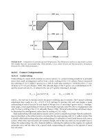
the sacrificial release etch. Since the proof-mass is typically by far the largest feature in an inertial sensor,
the release of the proof-mass from the substrate by a chemical etchant may require a substantial duration to
complete the lateral dissolution of the underlying sacrificial layer [Monk et al., 1994]. Designers often incor-
porate a series of etch holes through the structuretoexpedite the release, though this may require increas-
ing the size of the mass in order to maintain transducer performance. These sacrificial etch holes are shown
in Figure 2.4, in the proof-mass of the Freescale Semiconductor, Inc. Z-axis inertial sensor design. Va rious
chemical mixtures have been developed specifically to improve the rate and quality of inertial sensor release
[Williams et al., 2003; Overstolz et al., 2004].
2.4.2 Converting Force to Displacement: The Elastic Spring
The elastic spring is required to provide kinematic displacement of the proof-mass in the axis of sensitivity;
this will produce a suitable sense signal while being sufficiently rigid in other axes to eliminate cross-axis
d
2
x
ᎏ
dt
2
2-6 MEMS: Applications
Support Rim
Poly
Electrode
A
A
FIGURE 2.3 Scanning electron micrograph of an ultra-high-resolution X-lateral accelerometer with micro-g
resolution. (Photo courtesy of K. Najafi, University of Michigan.)
© 2006 by Taylor & Francis Group, LLC
sensitivity. The force obtained from an applied acceleration produces an opposite restoring force accord-
ing to Equation 2.6, where K is the elastic spring constant tensor (N/m) and x is the spatial displacement
of the mass with respect to the reference frame generated by the inertial load:
F ϭ ϪKx. (2.6)
In the ideal case, the proof-mass displacement is well controlled and in one axis only. The ratio of the proof-
mass to spring constant defines the sensitivity of the system to inertial loads.
The spring constant associated with the proof-mass suspension is governed by its geometry and material
properties. An initial approximation for one dimension can be made using the standard equation for the
deflection of an anchored cantilever beam under a point force applied at the opposite end:
k ϭ . (2.7)
E is the modulus of elasticity (Pa) for the spring material and h, w, and l are the thickness, width, and length
(m), respectively, of the beam. Micromachined springs are often folded or bent around a radius to improve
the performance of the overall device; consequently, spring constant estimates require combinations of
individual segment values [Boser and Howe, 1996]. Bent beams are often used to relieve residual intrinsic
stress in the micromachined material and stabilize device parameters across wafers and production lots.
Folded beams perform this function as well as reduce the device topology for the overall structure. They also
improve the sensitivity of the inertial sensor to package stress by reducing the spacing between anchored
points of the springs around the periphery of the sensor structure, as shown in Figure 2.4. It should be
noted that Equation 2.7 is intended only to serve as an estimate for the purpose of initial design;
computer-based simulation through finite element modeling or other means is highly recommended.
For a lateral accelerometer, increasing the out-of-plane stiffness proves to be one of the major challenges
for many micromachining technologies. Out-of-plane stiffness strongly impacts drop shock immunity and
cross axis sensitivity. Increasing the thickness of the beam increases this value by the third power, while
Ehw
3
ᎏ
4l
3
Inertial Sensors 2-7
FIGURE 2.4 (See color insert following page 2-12.)Topview micrograph of a Z-axis accelerometer quadrant showing
a folded spring and sacrificial etch holes designed into the proof-mass structure. (Photo courtesy Freescale
Semiconductor, Inc.)
© 2006 by Taylor & Francis Group, LLC