The MEMS Handbook (1st Ed) - M. Gad el Hak Part 1 ppsx
Bạn đang xem bản rút gọn của tài liệu. Xem và tải ngay bản đầy đủ của tài liệu tại đây (189.72 KB, 6 trang )
The
MEMS
Handbook
© 2002 by CRC Press LLC
© 2002 by CRC Press LLC
I
Background and
Fundamentals
1 Introduction
Mohamed Gad-el-Hak
2 Scaling of Micromechanical Devices
William Trimmer, Robert H. Stroud
Introduction • The Log Plot • Scaling of Mechanical Systems
3 Mechanical Properties of MEMS Materials
William N. Sharpe, Jr.
Introduction • Mechanical Property Definitions • Test Methods • Mechanical
Properties • Initial Design Values
4 Flow Physics
Mohamed Gad-el-Hak
Introduction • Flow Physics • Fluid Modeling • Continuum
Model • Compressibility • Boundary Conditions • Molecular-Based
Models • Liquid Flows • Surface Phenomena • Parting Remarks
5 Integrated Simulation for MEMS: Coupling Flow-Structure-Thermal-Electrical
Domains
Robert M. Kirby, George Em Karniadakis, Oleg Mikulchenko,
Kartikeya Mayaram
Abstract • Introduction • Coupled Circuit-Device Simulation • Overview of
Simulators • Circuit-Microfluidic Device Simulation • Demonstrations of the Integrated
Simulation Approach • Summary and Discussion
6 Liquid Flows in Microchannels
Kendra V. Sharp, Ronald J. Adrian,
Juan G. Santiago, Joshua I. Molho
Introduction • Experimental Studies of Flow Through Microchannels • Electrokinetics
Background • Summary and Conclusions
7 Burnett Simulations of Flows in Microdevices
Ramesh K. Agarwal,
Keon-Young Yun
Abstract • Introduction • History of Burnett Equations • Governing Equations •
Wall-Boundary Conditions • Linearized Stability Analysis of Burnett Equations •
Numerical Method • Numerical Simulations • Conclusions
8 Molecular-Based Microfluidic Simulation Models
Ali Beskok
Abstract • Introduction • Gas Flows • Liquid and Dense Gas Flows • Summary and
Conclusions
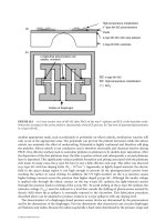
FIGURE 1.1
Scale of things, in meters. Lower scale continues in the upper bar from left to right. One meter is 10
6
µ
m, 10
9
nm or 10
10
Å.
Typical Man-Made
Devices
10
20
10
18
10
16
10
14
10
12
10
10
10
8
10
6
10
4
10
2
10
2
10
0
10
-2
10
-4
10
-6
10
-8
10
-10
10
-12
10
-14
10
-16
Diameter of Proton
© 2002 by CRC Press LLC
© 2002 by CRC Press LLC
2
Scaling of
Micromechanical
Devices
2.1 Introduction
2.2 The Log Plot
2.3 Scaling of Mechanical Systems
2.1 Introduction
A revolution in understanding and utilizing micromechanical devices is starting. The utility of these
devices will be enormous, and with time these microdevices will fill the niches of our lives as pervasively
as electronics. What form will these microdevices take? What will actuate them, and how will they interact
with their environment? We cannot foresee where the developing technology will take us.
How, then, do we start to design this world of the micro? As you will discover in this book, there are
a large number of ways to fabricate microdevices and a vast number of designs. The number of possible
things we could try is beyond possibility. Should we just start trying approaches until something works?
Perhaps there is a better way.
Scaling theory is a valuable guide to what may work and what will not. By understanding how phenomena
behave and change, as the scale size changes, we can gain some insight and better understand the profitable
approaches. This chapter examines how things change with size and will develop mathematics that helps
find the profitable approaches.
Three general scale sizes will be discussed: astronomical objects; the normal objects we deal with,
called
macro-objects
; and very small objects, called
micro-objects
. Things effective at one of these scale
sizes often are insignificant at another scale size. As an example, gravitational forces dominate on an
astronomical scale. The motion of our planet around the sun and our sun around the galaxy is driven
mostly by gravitational forces. Yet, on the macroscale of my desk top, the gravitational force between two
objects, such as my tape dispenser and stapler, is insignificant. A few simple scaling calculations later in
this chapter will tell us this: On astronomical scales, be concerned with gravity; on smaller scales, look
to other forces to move objects.
What is obvious on an astronomical-scale size or on a macroscale size is often not obvious on the
microscale. For example, take the case of an electric motor. It is really a magnetic motor, and almost all
macrosized electric actuators use magnetic fields to generate forces. Hence, one’s first intuition would
be to use magnetic motors in designing microdevices. However, most of the common micromotor designs
use electrostatic fields instead of magnetic. The reasons for this will become obvious in the following
discussion of how forces scale.
William Trimmer
Belle Mead Research
Robert H. Stroud
The Aerospace Corporation
© 2002 by CRC Press LLC
3
Mechanical Properties
of MEMS Materials
3.1 Introduction
3.2 Mechanical Property Definitions
3.3 Test Methods
Specimen and Test Structure Preparation • Dimension
Measurement • Force and Displacement Measurement • Strain
Measurement • Tensile Tests • Bend Tests • Resonant
Structure Tests • Membrane Tests • Indentation Tests • Other
Test Methods • Fracture Tests • Fatigue Tests • Creep
Tests • Round Robin Tests
3.4 Mechanical Properties
3.5 Initial Design Values
Acknowledgments
3.1 Introduction
New technologies tend to originate with new materials and manufacturing processes, which are used for
new products. In the early stages, the emphasis is on novel devices and systems as well as ways of making
them. Studies of fundamental issues such as mechanical properties and design procedures come later.
For example, in 1830 there were 23 miles of railroad track in the U.S., but by 1870 there were 53,000 miles
of track. However, the Bessemer steelmaking process did not originate until 1856, and the American
Society for Testing and Materials (ASTM) was not organized until 1898.
The same is true for microelectromechanical systems (MEMS). The emphasis over the past dozen or
so years has been on new materials, new manufacturing processes, and new microdevices—and rightfully
so. These technological advances have been paralleled by an increasing interest in mechanical testing of
materials used in MEMS. More researchers are becoming involved, with the topic appearing in symposia
sponsored by the Society for Experimental Mechanics, the American Society of Mechanical Engineers,
and the Materials Research Society. Further, the November 2000 ASTM symposium, “Mechanical Testing
of Structural Films,” was an important first step toward standardization of test methods. This increase
in MEMS material testing has occurred over the past ten or so years, and this chapter is a review of the
current status of the field.
Mechanical properties of interest fall into three general categories: elastic, inelastic, and strength. The
designer of a microdevice needs to know the elastic properties in order to predict the amount of deflection
from an applied force, or vice versa. If the material is ductile and the deformed structure does not need
to return to its initial state, then the inelastic material behavior is necessary. The strength of the material
must be known so that the allowable operating limits can be set. The manufacturer of a MEMS device
needs to understand the relation between the processing and the properties of the material.
William N. Sharpe, Jr.
Johns Hopkins University
© 2002 by CRC Press LLC
4
Flow Physics
4.1 Introduction
4.2 Flow Physics
4.3 Fluid Modeling
4.4 Continuum Model
4.5 Compressibility
4.6 Boundary Conditions
4.7 Molecular-Based Models
4.8 Liquid Flows
4.9 Surface Phenomena
4.10 Parting Remarks
One of the first men who speculated on the remarkable possibilities which magnification or diminution
of physical dimensions provides was Jonathan Swift, who, in
Gulliver’s Travels,
drew some conclusions
as to what dwarfs and giants would really look like, and what sociological consequences size would
have. Some time ago Florence Moog (
Scientific American,
November 1948) showed that Swift was
a “bad biologist,” or Gulliver a “poor liar.” She showed that a linear reduction in size would carry
with it a reduction in the number of brain cells, and hence a reduction in intellectual capacity in
Lilliputians, whereas the enormous Brobdingnagians were physically impossible; they could have had
physical reality only if their necks and legs had been short and thick. These 90-ton monsters could never
have walked on dry land, nor could their tremendous weight have been carried on proportionately-sized
feet.
Even though Swift, in his phantasy, committed a number of physical errors, because he was not
sufficiently aware of the fact that some physical properties of a body are proportional to the linear
dimensions (height), whereas others vary with the third power of linear size (such as weight and cell
number), yet he surpassed his medieval predecessors in many respects and drew a number of excellent
conclusions, bringing both giants and dwarfs close to physical reality
.
(From “The Size of Man,” by F.W. Went,
American Scientist
56
(4), pp. 400–413, 1968.)
4.1 Introduction
In this chapter, we review the status of our understanding of fluid flow physics particular to microde-
vices. The chapter is an update of an earlier publication by the same author [Gad-el-Hak, 1999]. The
coverage here is broad, leaving the details to other chapters in the handbook that treat specialized
problems in microscale fluid mechanics. Not all microelectromechanical systems (MEMS) devices
involve fluid flows, of course, but this chapter will focus on the ones that do. Microducts, micronozzles,
micropumps, microturbines and microvalves are examples of small devices involving the flow of liquids
Mohamed Gad-el-Hak
University of Notre Dame