Foundation Flash CS4 for Designers- P3 doc
Bạn đang xem bản rút gọn của tài liệu. Xem và tải ngay bản đầy đủ của tài liệu tại đây (1.01 MB, 30 trang )
39
LEARNING THE FLASH CS4 PROFESSIONAL INTERFACE
Graphic symbols’ timelines are locked in step with the timeline they’re in,
unlike movieclip symbols, whose timelines run independently. This explains
why graphics are the de facto symbol for JibJab-style animation (dppl6++
sss*fe^f]^*_ki). Complex nested symbols can be scrubbed in this way for
testing in the timeline, whereas movieclips only show nested animation when
published. A symbol placed on the stage is called an instance. We will cover
symbols in Chapter 3, and animation in Chapters 7 and 8.
3. Select the tree on the lower of the two tree layers. Use these values to precisely place the
selected tree on the stage, resize it, and darken it:
X: 49
Y: 178.5
W: 65
H: 105
Color Effect: Tint
Tint Color: #000000 (black)
Tint Amount: 48%
The tree gets smaller, moves to the left side of the stage, and darkens. Resizing the image and
darkening it give the illusion of depth in this scene.
4. Select the remaining tree and use these values in the Property inspector:
X: 76.2
Y: 160.6
W: 68
H: 123
Color Effect: Tint
Tint Color: #000000 (black)
Tint Amount: 26%
The tree gets a bit smaller, moves to the left side of the stage, and, due to the low tint amount,
becomes a bit brighter than the tree behind it, as shown in Figure 1-39. The reason for this is that it
will be lit by the moon, which you will create in a couple of minutes.
If you have used Flash prior to this version, setting the location and size prop-
erties of a selected object using the Property inspector will, as one of the
authors discovered, take a bit of “brain rewiring.” In previous versions, the
first properties you changed, due to their location in the Property inspector,
were width and height; then you set the x and y coordinates. These have been
reversed in the Position & Size area in Flash CS4.
40
CHAPTER 1
Figure 1-39. Location and size are other properties that can be manipulated
using the Property inspector.
Let’s finish off the scene by adding the grass and the lake.
5. Add a new layer named Grass. With this new layer selected, drag the Grass movieclip from
the library to the stage. Set its
X and Y values in the Property inspector to -277.6 and 268.9,
respectively.
What’s with the decimals? This is deliberate. You need to know how to input
values as well as scrub the values. You may have noticed that when you scrub
values, the numbers don’t have decimals. If precise placement of objects on
the stage is “mission-critical,” you need to know that typing the numbers by
hand accomplishes this task. But isn’t a decimal value smaller than a pixel?
You bet it is, but we’re dealing with vector graphics here, and vectors don’t
need to sit exactly on a pixel.
6. Add a new layer named Lake. With this new layer selected, drag the Lake movieclip from the
library to the stage. Set its
X and Y values in the Property inspector to -252 and 274, respectively.
So far, so good. It is starting to look like Lake Nanagook (see Figure 1-40), but we need to add two
more elements to make it a bit more realistic: the moon and a twinkling star. We obviously need the
moon because it is reflected in the lake, and a twinkling star is a subtle bit of eye candy that will make
the scene that much more interesting and catch the viewer’s attention. Let’s start with the star.
41
LEARNING THE FLASH CS4 PROFESSIONAL INTERFACE
Figure 1-40. The project is starting to come together.
Using a motion tween to create a twinkling star
One of the steady messages running throughout this chapter is that we, as Flash designers, are illusion-
ists. In this exercise, you will discover how to create the illusion of a star twinkling in the night sky.
1. Open the library and double-click the star movieclip to open it in the Symbol Editor. When the
movieclip opens, you will see that it is composed of a layer named
diamond. The shape on the
stage was created using the
Rectangle Primitive tool, making the sides concave and filling the
shape with #FFCC00, which is a gold color.
If the shape is too small, select the Zoom tool (with the magnifying glass
icon) on the Tools panel, and click and drag it across the star. This is how you
can precisely zoom in on an object on the stage.
2. Add a new layer named diamond2. Click the star in the diamond layer and copy it to the clip-
board.
3. Select the first frame of the diamond2 layer and select Edit ° Paste in Place.
4. Move the playhead back to frame 1 and click the star. This will select the star in the diamond2
layer.
5. In the Property inspector, change the star’s Fill Color, in the Fill & Stroke area, to #FFFF99, which
is a faint-yellow color.
6. With the star in the diamond2 layer selected, right-click (Ctrl-click) the star to open its context
menu. Select
Convert to Symbol. In the New Symbol dialog box, name the symbol star2 and
select
Movie Clip from the Type drop-down list. Click OK to accept the change.
You need to convert the rectangle primitive to a symbol in order to apply the sort of tween you’re
about to do. Note that converting a symbol from a shape or primitive already in place keeps every-
thing positioned where it was.
42
CHAPTER 1
If you are an After Effects user, you are about to discover the
Motion Editor panel is a very familiar
place. If you are new to Flash or have never used After Effects, you are about discover that creating
motion in Flash has moved, in one leap, from a general tool to a finely tuned precision instrument. We
will be getting deeper into this panel in Chapter 8, which means the intent of this exercise is to give
you an opportunity to take the
Motion Editor panel for a short spin around the block. In this exercise,
you are going to do nothing more than have the star rotate 360 degrees in a clockwise direction, and
best of all, it requires only a couple of mouse clicks.
7. Right-click (Ctrl-click) on any frame in the diamond2 layer to open the context menu. When the
menu opens, select
Create Motion Tween. The span will turn blue. Open the Motion Editor panel
and move the playhead to frame 60 of the timeline.
8. In the Basic motion area, set the Rotation Z value to 360. When you finish, you will see that
a motion tween has been added to the timeline, as shown in Figure 1-41. Positive values will
rotate an object in a clockwise direction; negative values will rotate the object in a counter-
clockwise direction.
Figure 1-41. Putting a star in motion
9. Scrub across the frames to see the rotation.
10. Zoom the stage to the 100% view, and click the Scene 1 link on the top left of the stage to
return to the main timeline.
11. Save the project.
43
LEARNING THE FLASH CS4 PROFESSIONAL INTERFACE
Adding a moon over Lake Nanagook
To this point, we have essentially handed you the assets and let you put them in place and otherwise
manipulate them. It is now your turn to go solo and create the moon that rises over Lake Nanagook,
complete with shadow.
1. Select Insert ° New Symbol. This will open the New Symbol dialog box. Name the symbol Moon
and select
Movie Clip as its Type. Click OK. The dialog box will close, and the Symbol Editor will
open.
So far, we have used the term movieclip and not put a space between the
two words. The use of the single word has developed into a standard when
writing about Flash. The New Symbol dialog box is actually one of the very
few places that Adobe uses the two-word form.
2. Rename Layer 1 to bg. Add a new layer named shadow. The shadow layer should be above the
bg layer.
3. In the Tools panel, click and hold the Rectangle tool, and when the tool drop-down list appears,
select the
Oval tool. In the options area of the Tools panel, hover until you find the Object
Drawing
button (a tooltip will tell you when you’ve hit it; this is the button adjacent to the
horseshoe magnet). Make sure the
Object Drawing button is not selected before completing
the next few steps.
4. Click the Stroke Color chip in the Property inspector to open the Color Picker. Select the red on
the left as the stroke color (
#FF0000). Click the Fill color and select a light blue. While you’re
there, give the
Stroke a value of 3 to help it show up better.
5. Select the first frame of the bg layer and, with the Oval tool selected, click the stage and drag
out a circle. Switch to the
Selection tool and double-click the circle to select both the fill and
the stroke. In the
Property inspector, change the circle’s width and height values to 120, making
a perfect circle, and set the
X and Y values to 0. This is your moon (well, the beginnings of it).
6. With the moon still selected—again, you’ve selected both the stroke and the fill—copy it to
the clipboard.
7. Select the first frame in the shadow layer and paste the shape from the clipboard into this
layer.
8. With the newly pasted shape still selected, move it upward and to the left, so that it overlaps
the bottom layer, but both circles show. These shapes should look something like what you see
in the movies when a character looks through binoculars.
9. Click the Show All Layers as Outlines button to temporarily display both circles as outlines. The
intersection between the two shapes should look like football or rugby ball. Click the
Show All
Layers as Outlines
button again to exit outlines mode.
10. Click the red stroke on the shape in the shadow layer to select it. Press the Delete key to
remove it. You now have a solid blue circle over another circle that has a red stroke, as shown
in Figure 1-42.
44
CHAPTER 1
Figure 1-42. The moon shadow starts out as a couple of circles.
11. Select the red stroke around the circle in the bg layer and cut it to the clipboard. Select the
shadow layer and select Edit ° Paste in Place.
What has happened here is that the stroke you just pasted into the
shadow layer has actually cut the
football shape for you. The reason this is possible is because you turned off Object Drawing mode in
step 3. You’ll learn more about this mode in Chapter 2.
12. In the shadow layer, click the portion of the blue circle that is outside the stroke. Press the
Delete key. Now select and delete the stroke itself. If you turn off the visibility of the
bg layer,
you will see that you have created the shadow shape. Let’s make it a true shadow.
13. Click the football shape to select it, and then open the Color panel by selecting Window ° Color.
14. Set the fill color to #000066 and reduce the alpha value to 36%. Turn on the visibility of the bg
layer, and you will see that you indeed have a shadow, as shown in Figure 1-43.
The final task in the process of creating the moon is to add a gradient fill in order to give it a bit of a glow.
15. Select the circle in the bg layer and open the Color panel.
16. Select Radial from the Type drop-down list. The moon turns into a black-and-white radial
gradient. Click the black crayon to select it. Change the hex color under the Color Picker to
#C4DDEE. Click the white crayon and change its color to #93BDE0. The moon takes on a faint
glow, thanks to the similar colors in the gradient, as shown in Figure 1-44.
45
LEARNING THE FLASH CS4 PROFESSIONAL INTERFACE
Figure 1-43. The shadow is created by using the Color panel.
Figure 1-44. Add a radial gradient through the Color panel.
17. Click the Scene 1 link to return to the main timeline.
18. Add a layer named Star and another named Moon. These layers should appear above the others.
19. Add the star symbol to the Star layer, and set its X and Y values to 219 and 42, respectively.
20. Add the moon symbol to the Moon layer, and set its X and Y values to 241 and 43, respectively.
Making some moonshine
Next, let’s really make the moon and the star shine in the sky over Lake Nanagook. Let’s add a glow
effect to both of them. Here’s how:
46
CHAPTER 1
1. Select the star on the stage and click the Filters twirlie on the Property inspector to open the
Filters area.
2. Click the leftmost icon at the bottom of the Filters area to open the Add Filter menu list of the
filters. Select the
Glow filter.
3. Use these settings in the Glow filter:
Blur X: 14 Quality: High
Blur Y: 14 Color: #93BDE0
Strength: 418%
The star looks like it is about to go into supernova. Let’s make it a bit smaller.
4. With the star selected on the stage, set its width and height values in the Property inspector to 13.
5. Select the moon on the stage and apply the following Glow filter values:
Blur X: 26 Quality: High
Blur Y: 26 Color: #93BDE0
Strength: 70%
6. The moon and the star now look like they belong together in the sky, as shown in Figure 1-45.
Save the project.
Filters can be added only to movieclips, text fields, and buttons.
Figure 1-45. Adding a filter to a movieclip
47
LEARNING THE FLASH CS4 PROFESSIONAL INTERFACE
Breaking the stillness of the night at Lake Nanagook
If we are going to have an outdoor scene, it only makes sense to add a bit of outdoor sound to the mix.
Fortunately, adding audio to a Flash file is not terribly complicated.
1. Add a new layer and name it Audio.
2. Open the library and locate the imported J]j]ckkg*il/ audio file. Double-click it to open the
Sound Properties dialog box.
3. Click the Advanced button to reveal all of the features of this dialog box, as shown in Figure 1-46.
Click the
Test button to preview the audio file. Ah, the sounds of crickets and wolves howling in
the night. Click
OK to close the dialog box.
Figure 1-46. Preview sound in Flash by clicking the Test button.
4. With the Audio layer selected, drag the sound file from the library onto the stage. When you
release the mouse, the audio waveform appears in the layer.
Dragging a sound file from the library to the stage isn’t the only way to get an audio file to
the timeline. In many respects, what we’ve shown is not exactly regarded as a best practice
because audio can be big, and when it is in the library, it can increase the SWF size. We
have a whole chapter, Chapter 5, devoted to audio best practice, so for now, let’s content
ourselves with getting sound into the presentation and getting it to play.
48
CHAPTER 1
5. Click anywhere on the sound’s waveform in the Audio layer, and you will see the Property
inspector
change to show the sound properties (open the Sound twirlie, if you necessary).
6. Click the Sync drop-down menu and select Stream, as shown in Figure 1-47.
7. Scrub across the timeline, and you will hear the audio file. This is possible because of the Sync
change you made in step 6. Drag the playback head to frame 1 and press the Return (Enter)
key. The sound will start playing, but it abruptly ends at frame 50. This is because the audio was
originally recorded for a slower movie frame rate.
Figure 1-47. Audio on the timeline, and the sound properties in the Property inspector
8. Scroll the timeline so you can see frame 130. Click into the Audio layer at frame 130 and drag
downward without lifting the mouse—until you hit the
Gradient layer. This selects the last
frame of all your layers. Press the F5 key. This adds enough frames to every layer so that the
sound has enough room to play out completely.
9. Save the file.
Picking up a pattern here? Get into the habit of saving the file every time you
do something major to your movie. This way, if the computer crashes, you
won’t have a lot of extra work in front of you trying to reconstruct the movie
up to the point of the crash.
You may have looked at Figure 1-47 and thought, “Hey, my Audio layer doesn’t look like yours.” Good
eye. Layers can also be made larger. To do this, right-click (Ctrl-click) on a layer’s name to open the
context menu. Select
Properties to open the Layer Properties dialog box, as shown in Figure 1-48. Select
200% in the Layer height drop-down list, or enter your own value. Click OK to accept the change.
49
LEARNING THE FLASH CS4 PROFESSIONAL INTERFACE
Figure 1-48. Even layers have their
own properties.
Testing your movie
You have created the animation and scrubbed through
the timeline, and everything looks like it is in order.
Now would be a good time to test your movie in Flash
Player. We can’t overstate the importance of this step in
your workflow. The procedure, as one of the authors is
fond of telling his students, is, “Do a bit. Test it. Do a bit
more. Test it.” Flash movies can be quite complex. Each
element you add to your movie adds to the complex-
ity of the movie. Developing the habit of regularly test-
ing your work, regardless of how simple it may be, will
point out mistakes, errors, or problems in the work that
you’ve just completed. What it comes down to is this:
do you really want to burrow through a complex movie,
and even more complex code, searching for an issue, or
do you want to catch it early?
To test your Flash movie, press Ctrl+Enter (Cmd+Return).
If you prefer to use a menu, select
Control ° Test Movie.
You will see an alert box telling you that the movie is being
exported, and the movie will open in Flash Player, as shown in Figure 1-49. You should see the star twinkling
in the sky and that all of the stuff that is outside the boundaries of the stage has been trimmed off.
If you open the folder where you saved the FLA file, you will see that a SWF file has also been added
to the folder.
Making the moon rise over Lake Nanagook
We’ve been gently reminding you that Flash involves the art of illusion. The other thing you need to
know is that Flash developers are fanatics about detail. They pay close attention to their environment,
and then try and mimic it in their projects.
Figure 1-49. Testing a movie in Flash Player
50
CHAPTER 1
In this final piece of this exercise, we are going to get you up close and personal with that last state-
ment. The plan is to have the moon rise into the night sky. On the surface, that sounds like a no-
brainer: tween the motion of the moon between its start position and its finish position. But that’s not
quite how it works.
This is a night scene, and if there is no moon, things are quite dark. They only light up when the moon
is in the sky. If you look at Lake Nanagook, you can see there is a problem. The lake already contains
the reflection of the moon. The lake should be dark and only start to light up as the moon rises in the
sky. The other issue is the trees. They, too, are lit by the moon. but they should be dark and start to
light up as the moon rises.
Although fixing the movie may sound rather complex, it can all be handled by the
Property inspector and
Motion Editor panel. Follow these steps to start yourself on the path to becoming a fanatic about detail:
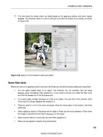
1. The first issue is the moon itself. It is in a higher layer. This means that if you animate the moon
in its current position, it will appear to rise in front of Lake Nanagook. Drag the
Moon layer
down to just above the
Gradient layer. Now the moon will rise behind the mountains.
2. Turn off the visibility of the Lake layer. You will need to see what you are doing, and the lake
will hide the start point of the moon rise.
3. Right-click (Ctrl-click) the Moon layer and select Create Motion Tween. This layer can now be
used with the
Motion Editor panel.
4. Select the Moon layer and open the Motion Editor panel.
5. Drag the playhead to frame 1 and, using the Position & Size area of the Property inspector, set
the moon’s position to
230 on the x axis and 305 on the y axis.
6. Drag the playhead to frame 50 and make sure the Basic motion twirlie is open. Add keyframes to the
X and Y rows by clicking the Add or Remove Keyframe button (the diamond) for either one of them.
7. Move the playhead to frame 100 and set the X and Y values to 241,43 (the original position of
the moon). If you scrub across the timeline—either in the
Timeline panel or the Motion Editor
panel—the moon rises from behind the mountains.
Want to earn some “bonus marks”? How about we have the moon travel through an arc to its final
position?
8. Lock the Mountains layer. You are going to manipulate the motion path—the series of dots—to
create the arc, and you don’t want to move the mountains by accident.
9. Click one of the dots where the path crosses the edge of the mountain range and drag it to the
left. A couple of things happened:
When you rolled the cursor over the path, an arc appeared under the arrow. This tells you
the path can be changed.
When you dragged the path, it changed to a solid line, which bent in the direction you were
dragging, and the graph in the
Motion Editor panel also bent. This tells you motion paths can
be thought of as vectors.
10. When you release the path, it becomes a dotted line again, as shown in Figure 1-50. Scrub the
playhead across the animation, and the moon follows a gentle arc as it moves into the night sky.
51
LEARNING THE FLASH CS4 PROFESSIONAL INTERFACE
Figure 1-50. Manipulating a motion path
If you are an experienced Flash user, you’ll notice the ability to directly edit a
motion path on the stage has replaced the Add Motion Guide button used
in previous versions of the application. Old-style motion guides are still avail-
able with classic tweens (see Chapter 7 for details).
Lighting up Lake Nanagook
Obviously, if the moon is behind the mountains when the movie starts, the lake and trees shouldn’t be
lit up. Let’s have them become distinct as the moon rises.
1. Unhide the Lake layer on the Timeline panel and right-click (Ctrl-click) to select Create Motion
Tween
. Drag the playhead to frame 1.
2. With the Lake layer selected, open the Motion Editor panel and click the + sign in the Color
Effect
area.
3. Select Brightness. Reduce the Brightness value to -100. This will turn the lake black because you
have essentially removed all of the color from the lake.
4. Drag the playhead to frame 50 and click the Brightness diamond to add a keyframe. Do this
again at frame 100 and increase the
Brightness value to 0%. The lake returns to its original
color state. Scrub across the timeline, and the reflection of the moon in the lake becomes
brighter as the moon moves across the night sky.
52
CHAPTER 1
5. Return to the Timeline panel and perform the next few steps with each tree layer in turn:
Right-click (Ctrl-click) at frame 50 and select Insert Keyframe. This adds a classic keyframe to
the layer at that position. Do the same at frame 100.
Right-click (Ctrl-click) anywhere in the layer between frames 50 and 100 and select Create
Classic Tween
.
Drag the playhead to frame 50. Click the tree in the current layer and use the Color Effect
area of the
Property inspector to change the tree’s Tint value to 100%, which completely
darkens that tree, as shown in Figure 1-51. (The keyframe at frame 100 still holds the tree’s
original
Tint value.)
Drag the playhead to frame 1 and change the tree’s Tint value to 100% there as well.
6. Save and test the movie. Your movie should look a lot more realistic. This tells you that the new
motion tween model and classic tweens can be combined.
You have concluded your introductory walk through Flash CS4 Professional.
Figure 1-51. The new Motion Tween model and classic tweens can be combined.
53
LEARNING THE FLASH CS4 PROFESSIONAL INTERFACE
What you have learned
In this chapter, you learned the following:
How to customize your Flash workspace
A number of methods for manipulating objects on the Flash stage
How to dock, undock, collapse, and minimize panels
The importance of the Property inspector in your daily workflow
The difference between a frame and a keyframe
The process involved in using frames to arrange and animate content and the properties of
content on the stage using the
Timeline and Motion Editor panels
How to add, delete, nest, and rearrange layers
How to test a Flash movie
In the next chapter, you’ll learn how to use the tools to create content in your movies, and how
Fireworks CS4, Photoshop CS4, and Illustrator CS4 are important elements in your workflow.
55
In the previous chapter, we handed you a bunch of movieclips and graphics and
essentially said, “Here, you toss them on the stage.” In this chapter, we start digging
into how those objects were created. In fact, you are going to be drawing trees,
creating venetian blinds, and playing with Chinese dancers and T- shirts, among other
things. We will be looking at the Illustrator and Photoshop File Importers, and also
playing with JPG and GIF images.
Here’s what we’ll cover in this chapter:
Understanding Flash graphic fundamentals
Using the drawing tools
Working with fills, strokes, and gradients
Managing and working with color
Working with bitmap images
Importing images into Flash, including Fireworks, Illustrator, and Photoshop
documents
CREATING ARTWORK IN FLASH
Chapter 2
56
CHAPTER 2
The following files are used in this chapter (located in ?d]lpan,.+Atan_eoaBehao[?d,.+Atan_eoa+):
@a_k*bh] Benaskngo*bh]
Oln]u>nqod*bh] ?hkq`o*ljc
Cn]`eajpHk_g*bh] t)b]_pkn*]e
Ei]caBehh*bh] ^]jjan*lo`
Opkkho*flc sda]p[cn]oo[,-*lo`
@]j_an*flc sda]p[cn]oo[,.
Pn]_a*bh] sda]p[cn]oo[,/
FLC?kilnaooekj*bh] patp[beah`o[,-*lo`
FLC?kilnaooekj*osb patp[beah`o[,.*lo`
CEB*bh] ^]jjan*osb
?kqjpanbkn_a*ceb ^]jjan*bh]
The source files are available online from either of the following sites:
dppl6++sss*Bkqj`]pekjBh]od?O0*_ki
dppl6++sss*bneaj`okbA@*_ki+`ksjhk]`*dpih
Let’s start with the basics of Flash artwork.
Flash’s two kinds of artwork
Artwork in Flash comes in two flavors: vector and bitmap. Vector images are created in a drawing
application such as Illustrator CS4 or Fireworks CS4. When you draw an object on the Flash stage, you
are using the drawing tools to create a vector image directly in Flash. Bitmap images are created in
graphics applications such as Photoshop CS4 and Fireworks CS4, and imported into Flash (they actually
can be created in Flash, but only with the use of advanced ActionScript).
At its heart, Flash is a vector- drawing and animation tool. The great thing about vectors is their rela-
tively small file size compared to their bitmap cousins. Flash’s roots began as a vector- animation tool
(FutureSplash Animator) for the Web. When it was introduced, broadband was just getting established,
and the ubiquitous 56K modem was how many people connected to the Internet. In those days, size
was paramount. Vectors, being extremely small, load very quickly.
What makes vectors so appealing is that they generally require very little information and computing
power to draw. In very simplistic terms, a circle of 100 pixels in diameter can be described by five
points—four on the circle (north, east, south, and west) and one in the center—and those points are
used in a mathematical calculation that results in the diameter of that shape. The computer might
also need to know whether there is a stroke around the circle and whether the circle is being filled
with a solid color, a gradient, or nothing. If you assume the circle is yellow and the stroke is black and
1 point in width, the description of this circle needs only a handful of data: the five points, fill color,
stroke width, and stroke color.
57
CREATING ARTWORK IN FLASH
Its bitmap counterpart is treated a lot differently. Instead of requiring a limited amount of information
to draw the circle, each pixel’s location in the circle is charted and remembered. Not only that, but
each pixel requires three units of color information to produce the red, green, and blue values for
that pixel. Additionally, the computer also needs to map and draw each pixel in the background on
which the circle is sitting. This means that producing the yellow circle requires thousands of pieces of
information, which explains why bitmap images usually add a lot of weight to a SWF’s file size.
Every rose has its thorn, and you will encounter vector art that is
mind- bogglingly complex—with anchor points in the hundreds of thou-
sands, and even millions—so let your conscience (and a bit of testing) be
your guide. Create a test SWF with the artwork in its original vector format—
just the artwork in question, and nothing else. Then create a test SWF with
the artwork converted to JPG, TIF, or the like. Use the format that adds the
least weight to the SWF.
Vectors are also device- independent. This means they can be scaled to 200% and still maintain their
crisp edges. Scale a bitmap by that percentage, and the pixels become twice their original size. The
image degrades because the pixels are tied to the device displaying them, which, in this case, is a com-
puter monitor. If you’ve ever printed a photograph and seen a series of blocks in it, as if a mesh had
been laid over the image, you’ve experienced what can happen when a device- dependent format is
handled by another device.
What types of graphic objects does Flash support? Flash supports four types of graphic objects:
Shapes: These are vector drawings, usually created with the Flash drawing tools or files
imported into Flash from Illustrator CS4 or Fireworks CS4.
Drawing objects: These are an alternate sort of vector shape you can draw with the Flash
drawing tools. They behave differently from the shapes described in the first item, when com-
bined in the same layer, thanks to something called Object Drawing mode, which you’ll learn
about in this chapter.
Primitives: These are created with the Rectangle Primitive and Oval Primitive tools in the Tools
panel. They’re vector shapes yet again, but with a difference: they can be modified in nonde-
structive ways even after they’re drawn.
Bitmaps: These are raster images created in something like Photoshop CS4 and Fireworks CS4,
and then imported into Flash.
So much for the raw material. Now let’s look at the drawing tools in Flash.
There are a few additions to the drawing tools in Flash CS4: the 3D Translation
and 3D Rotation tools, and the Bone and Bind tools. These are major upgrades
to the lineup, and simply skimming over them in this chapter won’t be doing
you any favors. The 3D tools are covered in Chapter 9, and the Bone and Bind
tools are covered in Chapter 8.
58
CHAPTER 2
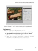
The Tools panel
The Tools panel, shown in Figure 2-1, is where all of your drawing tools are located. Used along with
Flash’s
Property inspector, effects, blends, and panels such as Color and Transform, Flash’s drawing tools
put a powerful, high- end graphics package at your disposal.
Figure 2-1. The Flash Tools panel
The tools can roughly be grouped into six distinct categories (they are not always logical
groupings), as follows:
Selection: The first two tools and the Lasso tool allow you select objects, select points within
objects, and even select a piece of an object. Thematically, the
Free Transform tool and 3D
Rotation
tool fit better in the modification category.
Drawing: The seven tools in this section—Pen tool through Deco tool—can be used to draw
images, create graphics and text elements, and draw shapes and lines.
Modification: The tools in this group—the Bone tool through the Eraser tool, plus the Free
Transform
and 3D Rotation tools—allow you manipulate the shape and angle of existing objects,
apply color changes to objects, and even remove a color or portions of an object. For example,
you use the
Paint Bucket tool to fill a shape or change its color. Color- related tools are typically
used in conjunction with the color modification category.
Viewing: The Hand tool and Zoom tool allow you to organize and magnify the stage while you
work.
59
CREATING ARTWORK IN FLASH
Color modification: The four tools in this area—Stroke Color through Swap Colors—
allow you to directly change colors of selected shapes or set the colors used by certain
modification tools.
Options: The options in this area change according to the tool you have selected.
For example, select the
Brush tool, and the options at the bottom will change to
allow you to choose the size of the brush, the type of brush, and so on, as shown in
Figure 2-2.
If you have used previous versions of Flash, you may notice that the tools
have not only been regrouped, but also the names for the grouping sec-
tions have been removed. Certain tools—Free Transform, 3D Rotation, Pen,
Rectangle, Brush, and Paint Bucket—have a small triangle at the bottom
right. Clicking these tools and holding for a few seconds opens a drop- down
menu that offers you a subselection of related tool choices. Color chips open
the Color Picker.
Selecting and transforming objects
The odds are almost 100% that Selection and Subselection are the tools you will use most frequently in
your everyday workflow. You’ll also find the
Free Transform tool indispensable, and its variant, Gradient
Transform
, very handy.
The Selection and Subselection tools
In the previous chapter, you used the Selection tool to move objects around the stage. It does a lot
more than that. Let’s experiment.
1. Click the Rectangle tool and make sure the Object Drawing button (in the Options section) is
deselected. Draw a rectangle on the stage. Don’t worry about colors for this exercise.
2. Switch to the Selection tool by either clicking it or pressing the V key. When you roll the tool
over the square, a cross with arrows appears under the cursor. This means you are hovering
over an object that can be moved by clicking and dragging.
Remember, all tools can be selected using the keyboard. If you roll the cursor
over a tool, a tooltip will appear, and the letter between the parentheses is
the key that can be pressed to select the tool.
3. Click the rectangle and drag to the right. Holy smokes, you just pulled the fill out of the rect-
angle (see Figure 2-3)! Press Ctrl+Z (Cmd+Z) to undo that last action.
Figure 2-2.
Select the
Brush tool,
and the
tool options
change.
60
CHAPTER 2
Figure 2-3. Selections in Flash aren’t always what they seem.
You have just discovered that Flash regards all objects you draw as being composed of two compo-
nents: a stroke and a fill. If you are an Illustrator, Photoshop, or Fireworks user, this may strike you as
being a bit odd, because in a vector universe, separating stroke from fill is not a common behavior.
Give us a minute, and we’ll ease you back into more familiar territory. We have a rectangle to move.
4. To select the entire rectangle, you have two choices. The first is to double- click the item. The
second is to “marquee” the stroke and the fill by drawing a selection box around the object.
To draw your selection box, click outside the rectangle near one of its corners, and then drag
toward the opposite corner. Go ahead and try both methods of selection, and then drag the
rectangle. You’ll see the whole thing move this time. You can also draw a selection with the
Lasso tool.
5. Actually, there is a third approach to selecting and moving the stroke and fill as a unit. Marquee
the object and select
Modify ° Group. Now, when you click the object, it is regarded as a single
entity and can be dragged at will.
The
Selection tool can be used for more than simply dragging objects around the stage. You can also
use it to modify the shape of an object. The stroke and fill of the rectangle on the stage, as you now
know, are both vector objects. This means they can be resized or reshaped and still retain their crisp
strokes and fills. Let’s see how that works.
6. Select your object on the stage and select Modify ° Ungroup. Place the tip of the cursor on
one of the strokes around the square. Do you see the little quarter circle below the arrow (see
Figure 2-4)? That symbol indicates that you can reshape the stroke.
Figure 2-4. The shape under the cursor
means the stroke can be reshaped.
7. Click and drag the stroke. When you drag the stroke, it actually bends. This tells you that the
stroke is anchored, and, as in Illustrator CS4 or Fireworks CS4, if you drag a point on a line
between two anchor points, the line changes its shape. The stroke uses the location where you
released the mouse as the apex of its new curve, as shown in Figure 2-5. And did you notice
that the fill also updates to reflect the new shape?
61
CREATING ARTWORK IN FLASH
Figure 2-5. Both the stroke and the fill will change to reflect the new shape.
8. Select the Subselection tool or press the A key to switch to this tool. Double- click one of the
corner points for the curve you have just created. The points and the handles become visible.
You can further adjust the curve by moving either the handles or the points. These handles are
only available on curves.
Another tool that allows you to manipulate objects on the stage is the
Free Transform tool, which we’ll
look at next.
The Free Transform tool
If there is such a thing as an indispensable drawing tool in Flash, the Free Transform tool may just be it.
This tool scales, skews, and rotates objects on the stage. Here’s how to use it:
1. Select the object on the Flash stage and select the Free Transform tool by either clicking it or
pressing the Q key. The selected object sprouts a bounding box with eight handles and a white
dot in the center.
2. Roll the cursor over each of the corner handles. Notice how the cursor develops a rotate icon,
as shown in Figure 2-6. This tells you that if you click and drag a corner, you can rotate the
object. Try it out. You should also see a ghosted representation of the original rotation, which
is a handy feature to ensure your transformation is correct.
Figure 2-6. Rotating an object using the Free
Transform tool
62
CHAPTER 2
3. Place the cursor on the bounding box. The cursor changes to split arrows. This tells you that
clicking and dragging will skew (or slant) the object in the direction in which you drag. Go
ahead and give it a try.
4. Place the cursor directly over one of the handles. It changes to a double- headed arrow, mean-
ing you can scale the object from that point.
The key to the
Free Transform tool is mastering that white dot. It is the transformation point of the
object. Rotations use that dot as a pivot, and any of the other transformations applied using this tool
are based on the location of that dot when you hold down the Alt key.
5. Click the white dot and drag it over the upper- left corner handle.
Rotate the object using the handle in the lower- right corner. The
rotation occurs around that white dot. Undo the change, and this
time scale the object using the bottom- right corner. Again, the
upper- left corner is used as the anchor for the transformation, as
shown in Figure 2-7.
6. Now try another skew. With the white dot close to one of the cor-
ners, but not actually in a corner, place the cursor on the bounding
box to see the split- arrows icon. Click and drag, and then hold down
the Alt key and drag again. See the difference? Do the same with
a scale transform.
To constrain the proportions of an object when using the mouse to scale the object, hold down the
Shift key before you drag the handle. You can use Shift at the same time as the Alt key, as described
previously, to both constrain and use the white dot as a pivot.
Have you applied a couple of transformations and now decided that you
don’t want to use them? To remove transformations, select Modify °
Transform ° Remove Transform or press Ctrl+Shift+Z (Cmd+Shift+Z). All
transform actions applied to the object will be removed.
The Gradient Transform tool
To the novice, gradients in Flash can be a little tricky. Moving the colors in the gradient around and
changing their direction is not done at the time the gradient is created; this manipulation is done using
a separate tool.
Let’s try a couple different techniques with gradients:
1. Select the Oval tool, deselect the stroke, and draw a circle on the stage. (To deselect the stroke,
choose the
Stroke color swatch with a red slash through it.)
2. With your circle drawn and selected, change the width and height values of the circle to 120
and
120 in the Property inspector.
3. Click the Fill color chip to open the Color Picker and select the predefined blue gradient at the
bottom of the panel, as shown in Figure 2-8.
Figure 2-7. Scaling an
object using the Free
Transform tool
63
CREATING ARTWORK IN FLASH
There are a couple of ways to change this gradient in order to posi-
tion the centered highlight elsewhere in the graphic. One method is
to use the
Paint Bucket tool. This tool simply fills a selected shape
with the color in the
Fill color chip, but it does something really
interesting when the color is a gradient.
4. Choose the gradient and click the Paint Bucket tool to select
it (or press the K key to switch to this tool).
5. Click in the upper- left corner of the circle. The center of the
gradient moves to the point where you clicked the mouse, as
shown in Figure 2-9. This happens because the “paint” pouring
out of the tool’s icon is the hotspot for the tool. The center of
the gradient will be the point where the “pour” is located.
Figure 2-9. The tip,
or “pour” point, of
the Paint Bucket’s
icon is its hotspot.
6. Click again somewhere else on the shape to reposition the
center point of the gradient.
The other technique for changing the gradient is to use the
Gradient
Transform
tool, which is more precise than using the Paint Bucket.
7. Click and hold on the Free Transform tool to open the drop- down menu and select the Gradient
Transform
. Alternatively, press the F key to switch from the current tool to the Gradient Transform
tool.
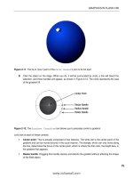
8. Click the object on the stage. When you do, it will be sur-
rounded by a circle, a line will bisect the selection, and
three handles will appear, as shown in Figure 2-10. The
circle represents the area of the gradient fill. Let’s look at
each of these controls:
Center point: This is actually composed of two fea-
tures. The white dot is the center point of the gradient
and can be moved around in the usual manner. The
triangle, which moves only along the line, determines
the focus of that center point. Dragging the triangle to
the edges can make the center point look a bit like
a comet.
Resize handle: Dragging this handle resizes and distorts the gradient without affecting the
size of the filled object.
Radius handle: Moving this handle inward or outward resizes the gradient proportionately.
Rotate handle: Drag this handle, and the gradient rotates around the center point. The
effect can be quite subtle with a radial gradient, but you’ll see a difference if you first
squeeze the gradient into a lozenge shape with the resize handle.
Figure 2-10. The Gradient Transform tool
allows you to precisely control a gradient.
Figure 2-8. Selecting a preset gradient
using the Fill color in the T
ools panel
64
CHAPTER 2
Now that you know how to use the tool on a radial gradient, give it a try on a linear gradient.
9. Select one of the linear gradients from the Fill color chip in the Tools panel.
10. Select the Rectangle tool and draw a square. Click the square with the Gradient Transform tool.
11. As you can see in Figure 2-11, most of the same gradient controls are in place. This time, two
lines appear. These lines indicate the range of the gradient. If you click the resize handle and
drag it downward toward the top of the box, the colors in the gradient become more com-
pressed. The rotate and center point handles work the same as with radial gradients.
Figure 2-11. The Gradient Transform tool can be used on
linear gradients as well.
Object Drawing mode
Introduced in Flash 8, the Object Drawing mode was greeted with wild cheering and dancing in the
streets. Well, it didn’t exactly happen that way, but a lot of designers became seriously happy campers
when they discovered this feature.
Prior to the release of Flash 8, shapes that overlapped each other on the stage were, for many, a frus-
trating experience. If one shape was over another—in the same layer—and you selected and moved
it, it would cut a chunk out of the shape below it. This is not to say it was a flaw in the application.
In Flash, once you understand the “one piece eats the other” phenomenon, it becomes a great con-
struction tool. It can be much simpler to throw down a base shape and take bites out of it to achieve
a complex figure than to draw the same figure from scratch. Object Drawing mode uses the opposite
concept. You get the best of both worlds, and the choice is yours.
When you select a drawing tool, the
Object Drawing icon appears in the Tools panel, as shown in
Figure 2-12. Click it, and the oval you are about to draw will be created as a separate object on the
stage. It will not automatically merge with any object under it, even on the same layer. Let’s see how
it works.