Foundation Flash CS5 For Designers- P5
Bạn đang xem bản rút gọn của tài liệu. Xem và tải ngay bản đầy đủ của tài liệu tại đây (1.34 MB, 50 trang )
SYMBOLS AND LIBRARIES
179
7.
This time leave the values alone, but select High as the Quality setting, and select Inner
shadow. The character takes on a bit of a 3D look to go with the shadow he is casting, as shown
in Figure 3-26.
Figure 3-26. Apply an inner shadow to add some depth.
Some filter facts
Before we move on to applying a blend, here are a few things you should know about adding and using filters:
You can apply multiple filters to an object. The character can, for example, have the Drop
Shadow, Glow, and Bevel filters applied to it. If you need to remove one, select the filter name
and click the Trash icon in the Filters area.
You cannot apply multiple instances of a filter to an object. You saw this in this exercise. Each
movie clip has a Drop Shadow filter applied to it.
Filters do result in a hit on the user’s processor when the movie plays in the browser. Use them
judiciously.
Filters applied to layers in Photoshop will be visible in Flash but will not be editable in Flash when
the image is imported into the Flash Library or to the stage.
Alpha channel video in a movie clip can have filters applied to it.
Filters can be applied to objects using ActionScript.
www.zshareall.com
Please purchase PDF Split-Merge on www.verypdf.com to remove this watermark.
CHAPTER 3
180
Playing with blends
The blend modes operate quite differently from the filters. If you are a Fireworks or Photoshop user, you
may already be familiar with the concept. In applications like those two, such modes are commonly used to
manipulate the colors of pixels to create new colors based on combinations with underlying pixels.
The blend modes in Flash are as follows:
Normal: No blend is applied, and the selection isn’t affected. Use this one to remove a blend.
Layer: This allows you to stack movie clips on top of each other with no effect upon their color.
Darken: This compares the foreground and background colors and keeps the darkest one.
Multiply: This multiplies the base color value by the blend color value and divides the result by
256. The result is inevitably a darker color.
Lighten: This is the opposite of darken with the result always being a lighter color.
Screen: This is the inverse of the blend color is multiplied by the base color. Think of this as
being the opposite of Multiply resulting in a lighter color.
Overlay: This multiplies, or screens, the colors depending on the base color. The base color is
not replaced. Instead, it is mixed with the blend color to reflect the lightness or darkness of the
original color.
Hard Light: This mimics the effect of shining a bright light through the selection. If the blend
color is darker than 50 percent gray, the image is darkened as if it were multiplied. This is another
way of adding shadows to a selection.
Add: The blend and base colors are added together resulting in a lighter color.
Subtract: The blend and the base colors are subtracted from each other resulting in a darker
color.
Difference: Depending upon their brightness values, either the base color is subtracted from
the blend value or vice versa. The result looks like a color film negative.
Invert: This inverts the base color.
Alpha: The blend color is converted to an alpha channel, which, essentially, turns transparent.
Erase: This is the base color including those of the background image are erased.
Blend modes, once you grasp that they are math-driven, work like this: the pixel colors values are
considered from two separate layers of an image and mathematically manipulated by the blend mode to
create the effect. An excellent example of this manipulation is the Multiply mode. This mode will
multiply the color values of a pixel in the source layer with the color values of the pixel directly below it in
the destination layer. The result is divided by 256 and is always a darker shade of the color. In Flash,
these calculations are performed on overlapping movie clips or buttons on the stage.
This book was purchased by
www.zshareall.com
Please purchase PDF Split-Merge on www.verypdf.com to remove this watermark.
SYMBOLS AND LIBRARIES
181
When applying a blending mode in Flash, keep in mind that it is not the same task as it is in Photoshop or
Fireworks. Flash lets you place multiple objects in a layer. When a blend mode is applied to a movie clip or
button in Flash, it is the object, which could be a photo, directly under the movie clip or button, which will
supply the color for the change in the movie clip or the button.
Blend modes are extremely powerful creative tools in the hands of a Flash artist. Though they can be
applied only to movie clips and buttons, applied judiciously, the blend modes can provide some rather
stunning visual effects. To apply a blend mode, you simply select the movie clip to which it is to be applied
and select the mode from the Blend drop-down menu in the Properties panel. Let’s look at a few of the
blend modes and learn some blend fundamentals along the way.
1.
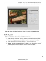
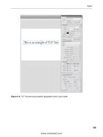
Open the Blend.fla file. When the file opens, you will see we have put two movie clips on the
stage (see Figure 3-27). The movie clips are also in separate layers named Source and
Destination. In this example, the Source layer contains some text filled with a neutral gray
color. The Destination layer contains an image of autumn leaves that were blurred using the
Gaussian Blur filter in Photoshop. Those layers have been given those names for a reason:
blending modes are applied in a top-down manner. This means that the effect will do the
manipulation using the source layer’s pixels and apply the result to the movie clip on the
destination layer. That’s right, anything visible under the source (including the stage) will be
affected by the transformation.
Figure 3-27. The pixels in the Source layer—the text—are used to create the effect with the pixels in the
destination layer—the blurred autumn leaves.
www.zshareall.com
Please purchase PDF Split-Merge on www.verypdf.com to remove this watermark.
CHAPTER 3
182
2.
Select the movie clip in the Source layer—the text—and click the twirlie in the Display area of
the Properties panel. Then select Normal from the Blending drop-down menu, as shown in
Figure 3-28. The Normal mode does not mix, combine, or otherwise play with the color values.
Figure 3-28. Blend modes are applied through the Properties panel.
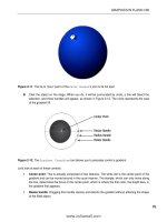
3.
With the text still selected, apply the Multiply mode. As you can see, Figure 3-29, the colors
have mixed, and the darker colors make the Source image darker. The important thing to notice
here is how the medium gray of the stage is also being used where the Source image overlaps
only the stage. If you return the mode to Normal, select the image in the Destination layer,
and apply the Multiply mode—the image will darken because of the dark gray color (#606060)
of the stage. Nothing happens to the text in the Source layer.
www.zshareall.com
Please purchase PDF Split-Merge on www.verypdf.com to remove this watermark.
SYMBOLS AND LIBRARIES
183
Figure 3-29. The Multiply mode
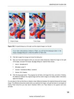
4.
Set the blend mode of the Destination layer to Normal. Select the text in the Source layer,
and apply the Lighten mode. In this example, as shown in Figure 3-30, the lighter color of both
the Source and Destination images is chosen. As you can see, the lighter pixels in the
Destination image are replacing the darker pixels in the Source image.
Figure 3-30. The Lighten mode
www.zshareall.com
Please purchase PDF Split-Merge on www.verypdf.com to remove this watermark.
CHAPTER 3
184
5.
Finally, select the image in the Source layer, and apply the Difference mode. This mode is
always a surprise. This one works by determining which color is the darkest in the Source and
Destination images and then subtracting the darker of the two from the lighter color. The
result, as shown in Figure 3-31, is always a vibrant image with saturated colors.
Figure 3-31. The Difference mode
Managing content on the stage
Now that you have had some fun, playtime is over. It is now time to get back to the serious issue of
managing your work. Though we have talked about using folders in layers and in the Library, we really
haven’t addressed the issue of managing the content on the stage.
As we have been telling and showing you to this point, you can determine the location of objects on the
stage by dragging them around. We look upon that practice, in many respects, as attempting to light your
BBQ with an atom bomb. You will light the BBQ, but taking out the neighborhood is a lot less precise than
striking a match and lighting a burner. This is why we have been doing it by the numbers. We enter actual
values into the Properties panel or use menus to precisely place items on the stage, and we resize and
otherwise manipulate content.
www.zshareall.com
Please purchase PDF Split-Merge on www.verypdf.com to remove this watermark.
SYMBOLS AND LIBRARIES
185
We’ll start by showing you how to group content:
1.
Open the NuttyProfessor.fla file in the Chapter 3 Exercise folder. When the file opens, head
over to the Library, and open the Professor movie clip.
2.
Click the Professor layer, and you will see that the drawing is composed of quite a few bits and
pieces (see Figure 3-32). If you wanted to move that drawing over a couple of pixels, you would
have to select each element to be moved. There is an easier method.
Figure 3-32. Line art, in many cases, is the sum of its parts.
3.
Select Modify
➤
Group, or if you are a keyboard junkie, press Ctrl+G (Windows) or Cmd+G
(Mac). The pieces become one unit, as indicated by the square surrounding them.
4.
Deselect the group by clicking the stage, and then click the image of the professor on the stage.
Again, you will again see the box indicating that the selection is grouped, and you will also be
given the same information in the Properties panel, as shown in Figure 3-33.
5.
To ungroup the selection, select Modify
➤
Ungroup, or press Ctrl+Shift+G (Windows) or
Cmd+Shift+G (Mac).
6.
Close the file without saving the changes.
www.zshareall.com
Please purchase PDF Split-Merge on www.verypdf.com to remove this watermark.
CHAPTER 3
186
Figure 3-33. A group is indicated both on the stage and in the Properties panel.
Aligning objects on the stage
Now that you know how to make your life a little easier by grouping objects, let’s turn our attention to how
objects can be aligned with each other on the stage. Reopen the NuttyProfessor.fla file.
The first technique is the use of Snap Align. You can switch on this very handy feature on and off by
selecting View
➤
Snapping
➤
Snap Align. When Snap Align is switched on, the default, dragging
one object close to another object, will show you a dotted line. This line shows you the alignment with the
stationary object.
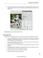
Click the words on the stage and slowly drag them toward the bottom-left corner of the movie clip. You will
see the Snap Align indicator line (see Figure 3-34) telling you that the left edge of the text is aligned with
the left edge of the movie clip. By dragging the text up and down the indicator line, you can align objects at
a distance. Release the mouse, and the text will snap to that line.
www.zshareall.com
Please purchase PDF Split-Merge on www.verypdf.com to remove this watermark.
SYMBOLS AND LIBRARIES
187
Figure 3-34. Using Snap Align
Snapping to the grid
You can also align objects on the stage through the use of a grid. This is a handy way of precisely
positioning objects on the stage. You can turn on the grid by selecting View
➤
Grid
➤
Show Grid. When
you release the mouse, a grid will appear on the stage. This grid is what we call an authortime feature.
That means that the grid won’t appear when you publish the SWF and put it up on a web page.
You can also edit the grid by selecting View
➤
Grid
➤
Edit Grid. The Grid dialog box, shown in
Figure 3-35, will appear. Here you can change the color of the grid lines, determine whether items snap to
the grid, and change the size of the squares in the grid. The Snap accuracy drop-down menu lets you
choose how snapping to the grid lines will be managed by Flash.
Figure 3-35. Adding a grid and managing it on the stage
www.zshareall.com
Please purchase PDF Split-Merge on www.verypdf.com to remove this watermark.
CHAPTER 3
188
Take another look at the Grid panel in Figure 3-35. There is a Show over objects
option that was added in Flash CS4. This option allows you to show the grid over
everything on the stage, meaning you now have the ability to be super accurate in
snapping objects to grid lines. As we said in the previous edition of this book, this option
is “super cool.”
Aligning with guides
Another method for aligning objects or placing them in precise locations on the stage is to use guides. You
can add guides by dragging them off either a horizontal or a vertical ruler. The ruler isn’t shown by default
in Flash; to turn it on, select View
➤
Rulers. At 100 percent view, the rulers are divided into five-pixel
units. If you need even more precise placement, zooming in to 2,000 percent view allows you to work in
units of .5 pixels.
To add a guide, drag it off of either the horizontal or vertical ruler, and when it is in position, release the
mouse. To remove a guide, drag it back onto the ruler.
Once a guide is in place, you can then edit it by selecting View
➤
Guides
➤
Edit Guides. This will
open the Guides dialog box (see Figure 3-36), which is quite similar to the Grid dialog box. The Snap
accuracy drop-down menu allows you to determine how close an object needs to be to a guide before it
snaps to the guide. You can also choose to lock the guides in place. Locking guides once they are in
position is a good habit to develop. This way, you won’t accidentally move them.
If you need to turn off the guides, select View
➤
Guide
➤
Show Guides; reselect it to turn them on
again. If you no longer need the guides, you can remove them with a single click of the mouse by selecting
View
➤
Guides
➤
Clear Guides.
Figure 3-36. Rulers, guides, and the Guide dialog box
www.zshareall.com
Please purchase PDF Split-Merge on www.verypdf.com to remove this watermark.
SYMBOLS AND LIBRARIES
189
Snapping in a guide layer and to pixels
Finally, you can snap objects to items in a guide layer—not to be confused with the guides we just
discussed—and even to individual pixels.
Snapping to an object in a guide layer is nothing more than a variation of the Snap to Objects, except
the layer in question has been converted to a guide layer by right-clicking (Control+clicking) the layer
name and selecting Guide. What’s the difference? As you saw in Chapter 1, the lines drawn in a guide
layer aren’t included in the SWF.
Snapping to pixels is best-suited to ultra-precise positioning and control freaks. This is extremely useful
with the placement of bitmaps and text fields. In fact, you won’t even see the pixel grid until you have
zoomed in to at least 400 percent. The pixel grid is not the same grid we demonstrated earlier.
Stacking order and using the Align panel
Layers are effective tools for managing content, but there is another related concept you need to be aware
of: stacking. When multiple objects are in a layer, the objects also have a front-to-back relationship with
each other, appearing to be placed on top of each other, which is called the stacking order.
Symbols, drawing objects, primitives, text fields, and grouped objects can be stacked. Everything else
essentially falls to the bottom of the pile in the layer. To accomplish this, each new symbol or group added
to a layer is given a position in the stack, which determines how far up from the bottom it will be placed.
This position is assigned in the order in which the symbols or objects are added to the stage. This means
that each symbol added to the stage sits in front, or above, the symbols or objects already on the stage.
Let’s look at this concept:
1.
Open the Stacks.fla file. You will see four photos on the stage.
2.
Drag the objects on top of each other, and you will see, as shown in Figure 3-37, a stack; the
location of each object in this stack is a visual clue regarding when it was placed on the stage.
www.zshareall.com
Please purchase PDF Split-Merge on www.verypdf.com to remove this watermark.
CHAPTER 3
190
Figure 3-37. Objects stacked in a layer
Stacking order is not fixed. For example, suppose you wanted to move the bread image to the top of the
stack and move the stairs image under the fountain image.
3.
Select the bread image on the stage, and select Modify
➤
Arrange
➤
Bring to Front. The
image moves to the top of the stack. This tells you that the Bring to Front and Send to
Back menu items are used to move selected objects to the top or the bottom of a stack.
4.
Right-click (Windows) or Control-click (Mac) on the stairs image to open the context menu.
5.
When the context menu opens, select Arrange
➤
Send Backward, as shown in Figure 3-38.
The stairs move under the fountain image. This tells you that the Bring Forward or Send
Backward menu items can be used to move objects in front of or behind each other. What you
have also learned is the Arrange menu is available in the Modify menu or by opening an
object’s context menu.
This book was purchased by
www.zshareall.com
Please purchase PDF Split-Merge on www.verypdf.com to remove this watermark.
SYMBOLS AND LIBRARIES
191
Figure 3-38. You can also use the context menu to change the stacking order of selected objects.
Throughout this book, we have talked about the use of layers to manage content. Obviously, stacking
objects on top of each other flies in the face of what we have said. Not so fast. There is an incredibly
useful menu item that actually allows you to bring a bit of order to the chaos.
1.
Select all the items on the stage.
2.
Select Modify
➤
Timeline
➤
Distribute to Layers. When you release the mouse, the
order of the objects in relation to each other doesn’t change, but each object has been removed
from the original layer—Layer 1—and is now on its own named layer, as shown in Figure 3-39.
This is extremely useful, for example, when you import Photoshop layer folders as movie clips
and then you see that you need to break them into Flash layers.
3.
Close the file, and don’t save the changes.
Now that you see what you can do with this powerful menu item, you also need to understand some rules
regarding its use:
Symbols, shapes, drawing objects, primitives, text fields, and grouped objects will be placed on
their own individual layers.
For symbols, layer names are based upon either the instance name in the Properties panel or
the symbol name in the Library. If both the symbol name and the instance name are the same,
instance names take precedence.
For text fields the name of the layer is based on the text content—or the text field’s instance
name in the Properties panel. Again, instance names take precedence.
www.zshareall.com
Please purchase PDF Split-Merge on www.verypdf.com to remove this watermark.
CHAPTER 3
192
Figure 3-39. Distribute to Layers places each selected object on its own layer.
Using the Align panel
The Align panel allows you to line up and center objects and otherwise bring order to chaos with a click
or two of the mouse.
You can access the Align panel either by selecting Window
➤
Align or pressing Ctrl+K (Windows) or
Cmd+K (Mac) to open the panel shown in Figure 3-40. When the panel opens, you are presented with a
number of alignment options—there are 17 options available and a button labeled Align to stage. The
Align to stage button allows you to either align objects with each other or, if it is selected, align them
with the stage.
www.zshareall.com
Please purchase PDF Split-Merge on www.verypdf.com to remove this watermark.
SYMBOLS AND LIBRARIES
193
Figure 3-40. The Align panel
Let’s see how all of this works:
1.
Open the AlignPanel.fla file in the Chapter 3 Exercise folder. As you can see, the file
consists of a number of button components scattered across the stage. Open the Align panel.
2.
Select all the components, and being sure the Align to stage check box is not selected, click
the Left Align button in the panel. The buttons all line up along their left edges.
The addition of a check box to the Align to stage feature is a welcome change. Up
to this version of the application designers and developers constantly complained about
not knowing when the button was selected.
3.
Click the Vertical Spacing button in the Space options, and the components will be spaced
evenly on the vertical axis. Click the Distribute Top Edge button to even out the spacing.
Now let’s use the panel to create a button bar across the top of the stage.
4.
Click the Align to stage check box on the Align panel.
www.zshareall.com
Please purchase PDF Split-Merge on www.verypdf.com to remove this watermark.
CHAPTER 3
194
5.
Select all the buttons and click the Align Top Edge button. The buttons will all pile on top of
each other at the top of the stage.
6.
With the buttons still selected, click the Distribute Horizontal Center button. The buttons
spread out along the top of the stage, as shown in Figure 3-41. Not bad—two clicks, and you
have a button bar.
Figure 3-41. Two clicks is all it takes to create a button bar.
Masks and masking
Before we turn you loose on a project, the final subject we will be examining is the issue of masking in
Flash. As you know, masks are used to selectively show and hide objects on the Flash stage. The value of
a mask is, in many respects, not clearly understood by Flash designers. They tend to regard masking as a
way to hide stuff. They see it as an overly complicated method of doing something that could be more
easily done in an imaging application. This is not exactly incorrect, but what they tend to miss is that
masks in Flash can be animated and can even react to events on the stage. For example, one of the
authors connects a webcam to his computer and, using Flash, is able to broadcast himself peering out of
billboards in Times Square, waving at people walking by in Piccadilly Circus in London, or looking out of
the porthole of a sensory deprivation tank. When the camera is not connected, the images used revert to
their normal states.
Here you will learn to create simple mask, create a masked animation, and use text as a mask. Finally,
you’ll tackle creating a soft mask, an exercise designed to pull together much of what you have discovered
in this chapter.
A simple mask
In this exercise, we are going to show you the basic steps involved in a creating a mask in Flash. Once
you have the fundamentals under your belt, you can then apply what you have learned in a rather creative
manner. Let’s start:
www.zshareall.com
Please purchase PDF Split-Merge on www.verypdf.com to remove this watermark.
SYMBOLS AND LIBRARIES
195
1.
Open the SimpleMask.fla file.
2.
Add a new layer named Mask, and draw a circle with no stroke on the new layer.
3.
Right-click (Windows) or Cmd+click (Mac) on the Mask layer to open the Layer context menu.
Select Mask. When you release the mouse, the image of the frozen pond will look like it is
circular. You should also notice that the appearance of the layers has changed and that they are
locked (see Figure 3-42). The icon beside the Mask layer name (the rectangle with a cutout)
indicates that the layer is a mask, and the indent for the Cycle layer name indicates that it is the
object being masked.
Figure 3-42. Applying a mask
www.zshareall.com
Please purchase PDF Split-Merge on www.verypdf.com to remove this watermark.
CHAPTER 3
196
What you see is the image showing through the circle in the Mask layer, with the stage color visible. One
thing you need to know about masks is that you need to be careful dragging other layers under them. Do
that, and they, too, will be masked—depending on how you are doing the dragging. The following steps
explain what we’re getting at:
4.
Add a new layer above the mask, and name it Square. Select the Rectangle tool, and draw a
rectangle on this new layer.
5.
Drag the Square layer under the Blue Springs layer. When you release the mouse, the circle
and the square are visible. Click the Lock icon in the Square layer, and the square will
disappear because it is under the photograph.
The locks turn the masks on and off and allow you to edit or manipulate the content in
the layers, including the masks. When you finish making your changes, click the locks to
reapply the mask. When all layers are locked (the masked layers and the mask), the
mask goes into a preview mode.
6.
Unlock the Square layer, and drag it back above the Mask layer. This time, drag the Mask layer
above the Square layer. When you release the mouse, you will see that both the Mask and
Cycle layers have moved above the Square layer and that the shape in the layer is visible, as
shown in Figure 3-43.
7.
Drag the Square layer below the Blue Springs layer again, this time keeping to the left. When
you release the mouse, the Square layer is no longer associated with the mask. This is an
alternative method of toggling between the Normal and Masked (or Mask) layer options seen
when you right-click (Windows) or Control-click (Mac) a layer and select Properties.
8.
Close the file without saving the changes.
www.zshareall.com
Please purchase PDF Split-Merge on www.verypdf.com to remove this watermark.
SYMBOLS AND LIBRARIES
197
Figure 3-43. Masking layers can be moved around.
Now that you understand the fundamentals, let’s get a little more complex.
Creating a masked animation
The art of Flash is, in many respects, the art of illusion. In this exercise, you’ll create the illusion of the
Dancing Fool from the Drop Shadow example earlier in the chapter sliding across six panels on a wall in
Adobe’s San Jose Headquarters building. The problem to contend with is the fact the panels are large, and
each panel has its own shape. How do you get the Dancing Fool to slide out from behind one panel,
across a few more and slide behind another as he exits the stage?
You think a bit differently.
The effect you want to create is shown in Figure 3-44. Instead of using the panels as the mask, you need
to use the colored area in each panel as the mask. The following steps show you how to accomplish this.
www.zshareall.com
Please purchase PDF Split-Merge on www.verypdf.com to remove this watermark.
CHAPTER 3
198
Figure 3-44. The Dancing Fool slides across colored panels.
1.
Open the Wall.fla file. All of the items you will need for this exercise are located in the
Library.
2.
Select the Magnifying Glass tool, and zoom in on the bottom six panels by clicking and
dragging the Magnifying Glass across them.
3.
Select the Pen tool, and draw a shape that matches the colored area without the triangle with the
dot in the bottom-right corner of each panel.
4.
Fill each shape drawn with the Pen tool with black by clicking inside it with the Paint Bucket
tool.
5.
Holding down the Shift key, select each of the shapes you have just drawn, and convert the
selection to a movie clip named Mask.
6.
Open the Mask movie clip in the Symbol Editor. Change Layer 1’s name to Panels, and
add a new layer named DancingFool to the timeline. Drag the DancingFool layer under the
Panels layer.
7.
Select frame 1 of the DancingFool layer, and drag a copy of the DancingFool movie clip to
the stage. Place the movie clip to the left of shapes in the Panels layer, as shown in Figure 3-45.
www.zshareall.com
Please purchase PDF Split-Merge on www.verypdf.com to remove this watermark.