Foundation Flash CS4 for Designers- P14 pdf
Bạn đang xem bản rút gọn của tài liệu. Xem và tải ngay bản đầy đủ của tài liệu tại đây (921.86 KB, 30 trang )
379
ANIMATION, PART 2
3. Click the tween layer to select it, and then right- click (Ctrl- click) and select Insert Keyframe °
Position
from the context menu, as shown in Figure 8-18. A property keyframe (small diamond)
will appear at frame 45.
Figure 8-18. Property keyframes can be added with the Timeline panel.
4. Switch to the Motion Editor panel and notice that one keyframe apiece has appeared in the X
and
Y graphs, which makes sense.
5. Select the lunatic symbol and move it downward. As you saw earlier in the chapter, property
keyframes are created for you automatically in the current frame when you change a symbol’s
position, scale, rotation, or the like. What you learned from step 3 is that it’s still perfectly okay
to create your keyframe first.
6. Switch back to the Timeline panel and right- click (Ctrl- click) again on frame 45. Note that you
have options for clearing keyframes and also determining which property keyframes to display
in the
Timeline panel.
Don’t be fooled by the
Clear Keyframe choice! You would think, because Insert Keyframe inserts the desired
keyframe(s) in the current frame, that
Clear Keyframe would follow suit and remove only keyframes in
the current frame. This is not so. By choosing
Clear Keyframe, you’re removing all property keyframes in
the current tween span. If you select
Clear Keyframe ° Rotation, for example, you remove all property
keyframes in the
Motion Editor panel’s Rotation Z graph, regardless of in which frame they appear.
Once you see these features and understand them for what they are, you’ll surely find them useful,
but the
Motion Editor panel does more.
380
CHAPTER 8
7. Open the Motion Editor panel and scrub the playhead of along the Motion Editor’s timeline. You
get the same sort of preview as the
Timeline panel. The difference is that the Motion Editor panel
also gives you a pair of arrows and a diamond, as shown in Figure 8-19.
Figure 8-19. In the Motion Editor panel,
keyframes can navigated, added, and
removed with this widget.
Keep an eye on the diamond as you scrub. When you drag the playhead to a frame that already con-
tains a keyframe, the diamond turns yellow. Use the left and right arrows to jump from keyframe to
keyframe. Arrows will temporarily become disabled, as appropriate, at the first and last keyframes.
8. Scrub to frame 15 and click the Y graph’s diamond. It turns yellow, and a new anchor point
appears in the
Y and X graphs at frame 15. (The Y and X graphs are synchronized, but this isn’t
the case with most property graphs.) Click the diamond again, and the keyframe disappears.
Click it a third time to bring the keyframe back.
9. With the new keyframe in place, use the mouse to drag the anchor point in the Y graph
upward, which correspondingly moves the lunatic downward on the stage. Note how the
anchor point snaps to frames if you slide it left and right. That makes sense, because you can’t
have a keyframe between two frames.
10. Move your mouse elsewhere in the Y graph, and then
hold down the Ctrl (Cmd) key while you hover over
one of the line segments. As shown in Figure 8-20, the
cursor turns into a pen with a plus sign, which indi-
cates you can click to add a new keyframe. Hover over
an existing keyframe while holding the Ctrl (Cmd) key,
and you’ll see a pen cursor with a minus sign. Click to
remove the keyframe.
11. Hold down the Alt (Option) key and hover over frame
30 in the
Rotation Z graph. The cursor turns into an
upside down V, as shown in Figure 8-21. Click, and this
converts the anchor point into a curve anchor, which can be adjusted with Bezier handles. The
effect of these handles on the
X and Y graphs isn’t always obvious, but for many properties, it
gives you a “quick-and- dirty” custom ease.
Figure 8-21. Anchor points can be con-
verted from corner points to smooth with
the Alt (Option) key.
12. Grab the right Bezier curve handle and drag it up and to the right so that the curve rises above
its 100% mark, as shown in Figure 8-22.
Figure 8-20. Keyframes can also be
added and removed with the mouse.
381
ANIMATION, PART 2
Figure 8-22. Anchor points can be manipulated with Bezier curve handles.
13. Press Enter (Return) to preview the animation, and you’ll see that the symbol rotates farther
than it did before—you’ve pushed it past its original destination, to approximately 160%—and
then eases back the
Rotation Z setting in the property keyframe at frame 60.
As helpful as the
Motion Editor panel is, sometimes less is more. When you want to compress or expand
the duration of a tween span, for example, the
Timeline panel is the only way to do it, if you want to do
it proportionally. If not, you could use either panel, but the
Timeline panel makes it easier.
Changing duration proportionally
The animation in the I]j]cejcGaubn]iao*bh] you were just using spans 60 frames. At 24 fps, that’s
approximately 2.5 seconds, which may or may not be what you want. To change a tween span’s dura-
tion proportionally, you’ll need to use the
Timeline panel. Here’s how:
1. Open the ?d]jcejc@qn]pekj*bh] file in the Chapter 8 Atan_eoa folder. Look in the Timeline
panel, and you’ll see a 60- second motion tween with five keyframes, four of which are prop-
erty keyframes.
382
CHAPTER 8
2. Move your mouse to the right edge of the tween span. You’ll see
the cursor turn into a double- headed arrow, as shown in Figure 8-23.
Click and drag toward the right. For example, shorten the tween
span so that it ends at frame 30. Notice that all four property key-
frames are still in place, and, proportionately speaking, are the
same relative distance from each other as before.
3. Click and drag the tween span so that it ends at frame 59. Now
release and drag the tween span to frame 60.
This time, the property frames are nearly back to their original places, but some are slightly off. That
makes sense, because frame 59 is an odd number, and Flash had to make a decision on how to shift
the frames to compensate.
To get the property keyframes back to frames 15, 30, and 45 exactly, you’ll need to use a different
approach. If you’re into tedium, you could switch to the
Motion Editor panel and visit every property
graph in turn, sliding numerous anchor points while holding the Shift key. The middle keyframe, espe-
cially, would give you a headache, as it affects the
X, Y, Rotation Z, Scale X, and Scale Y graphs. There’s
an easier way, and we describe it in the very next paragraph.
Changing duration nonproportionally
Sometimes you’ll want to change the duration between property keyframes, which may or may not
incorporate a change in span duration. You could do this with the
Motion Editor panel, visiting each rel-
evant graph and moving property keyframes individually, or you can update the keyframes in several
graphs at the same time. For that, use the
Timeline panel. Here’s how:
1. Continuing with ?d]jcejc@qn]pekj*bh], and still in the Timeline panel, hold down the Ctrl
(Cmd) key and click the keyframe closest to frame 30. Notice that holding down Ctrl (Cmd)
allows you to select a single frame in the tween span, rather than the whole span.
2. Now that you have a single property keyframe selected, release the Ctrl (Cmd) key, and then
click and drag the selected keyframe left or right along the timeline. Doing this effectively
selects all the anchor points for the current frame in the
Motion Editor panel and lets you move
them as one.
Motion paths
With the butterfly exercise in Chapter 7, you learned that a special kind of guide layer in the Timeline
panel, called a motion guide, lets you send a symbol along a potentially intricate path, braided with
loops and curves. This capability is equally possible with the
Motion Editor panel, only it’s called
a motion path, and it’s built directly into the tween layer. In fact, you’ve already seen this feature, even
if you didn’t notice it earlier in the chapter.
Manipulating motion paths
The most interesting thing about this Motion Editor panel feature is that its effects are easier to accom-
plish with the
Timeline panel. Let’s take a closer look:
1. Open IkpekjCqe`aOeilha*bh] from the Atan_eoa folder for this chapter. You’ll see the Chapter 7
butterfly positioned near the lower- left corner of the stage.
Figure 8-23. Drag the
tween span to increase or
decrease a tween’s duration.
383
ANIMATION, PART 2
2. Using the Timeline panel, apply a motion tween to frame 1. Then drag the playhead to frame 24
(or the last frame in the span). Drag the butterfly near the upper- right corner of the stage, and
notice the series of dots that represent the motion path.
3. Using the Selection tool, hover near the motion path and, just as you would edit a normal line,
click and drag to introduce a curve, as shown in Figure 8-24.
Figure 8-24. Motion paths can be manipulated directly.
4. Using the Subselection tool, click either anchor point and drag the Bezier curve handles to
increase the range of the curve. Do the same thing to the other anchor point. In Figure 8-25,
we’ve produced a sideways S- shaped motion path.
Figure 8-25. Use the Subselection tool to modify the motion path even further.
384
CHAPTER 8
Not only can you reshape the motion path as shown, you can also move it, rotate it, skew it, and effec-
tively treat it as you would any normal shape. Let’s keep experimenting.
5. Select the tween layer and cast your gaze to the Property inspector. Scrub the X, Y, W (width),
and
H (height) hot text values, and you’ll see that you can move and resize the motion path.
But wait, there’s more!
6. Open the Transform panel (Window ° Transform). This one’s a bit trickier, because if you don’t
select the actual motion path, Flash will think you want to transform the symbol instead.
7. Use the Selection tool to click anywhere along the motion path to select it. Now scrub the
Transform panel’s Rotate hot text to see the motion path pivot around its starting anchor point,
as shown in Figure 8-26.
Figure 8-26. Motion paths can even be rotated, skewed, and aligned.
8. To pivot around the other anchor point, right- click (Ctrl- click) the motion path and select
Motion Path ° Reverse Path from the context menu. Scrub the Rotate hot text again, and
change the location of the hinge. When you’re finished, reverse the path again to make the
butterfly animate from the bottom left to toward the top right.
9. Experiment with the Width, Height, and Skew properties in the same panel.
10. To perform these same transformations in a more organic fashion—that is, with your mouse,
rather than by the numbers—switch to the
Subselection tool and press the Ctrl (Cmd) key. Doing
so introduces a temporary bounding box around the motion path, as shown in Figure 8-27.
385
ANIMATION, PART 2
Figure 8-27. Hold down Ctrl (Cmd) to transform a motion
path with your mouse.
11. Hover near the various transform handles to see the mouse cursor change to indicate what
sort of transformation is possible. Click and drag to perform the transformation. The corner
handles manage rotation, the edge handles manage scale when you hover directly over them,
and the same edge handles manage skew when you hover just off center of them.
Don’t forget the Alt (Option) key while you make these transformations with the
mouse. Without it, transformations pivot around the bounding box’s center. With Alt
(Option), transformations pivot along the opposite corner or edge. In either case, the
Ctrl (Cmd) key is required to produce the bounding box.
12. Open the Align panel (Window ° Align) and, with the To stage button selected, align the motion
path to the horizontal and vertical center of the stage.
Notice, as with the classic tween version of this exercise, the nested animation of the butterfly performs
as expected. Because the graphic symbol has animation on its own timeline, the butterfly’s wings flutter
as it moves. (As a note of interest, that nested animation is composed of classic tweens. This is one of
many indications that the two tweening models coexist happily.)
Using advanced motion paths
In Chapter 7, the butterfly went on a pretty wild ride—nothing like the tame Bezier curves you’ve seen
so far in this chapter. You can do the same thing with the new tweening model, and you still don’t
need a motion guide layer. Here’s how:
1. Open IkpekjCqe`a?kilhat*bh] in this chapter’s Atan_eoa folder. You’ll see the finished version
of the butterfly IkpekjCqe`a*bh] exercise from Chapter 7, including a classic tween directed
by a motion guide layer. Your job—and it’s an easy one—is to convert that complex motion
guide into a motion path.
386
CHAPTER 8
2. Right-click (Ctrl- click) the flutter by (motion guide) layer and deselect Guide from the context
menu. This converts that layer back to a normal layer.
3. Using the Selection tool, double- click the wavy line to select the whole thing, and then cut the
curves to the clipboard (
Edit ° Cut).
4. Right-click (Ctrl- click) the classic tween and select Remove Tween from the context menu.
5. Right-click (Ctrl- click) again and select Create Motion Tween.
6. With the tween layer selected, paste the wavy line into the layer by selecting Edit ° Paste in
Place
. That’s all there is to it! If you like, delete the now- empty flutter by layer.
7. Click the tween layer again. Use the Property inspector to select or deselect Orient to path, which
behaves as it did for the classic tween version.
Motion tween properties
As you’ve seen throughout this book, the Property inspector is the most versatile panel in your arsenal,
simply because it changes to reflect whatever object is selected. When you’re dealing with motion
tweens, there are two things the
Property inspector lets you manipulate: the symbol and the tween
itself (that is, the motion path). Some of these properties are the ones you see for classic tweens, but
they don’t all apply for motion tweens.
Let’s take a look. Open any of the files you’ve used to far and make sure a motion tween is applied to
at least one symbol. Select the tween span, and you’ll notice the following properties in the
Property
inspector
:
Ease: This applies the Motion Editor panel’s Simple (Slow) ease to the full frame span selected.
You can adjust this ease’s hot text to a value from
-100 (ease in) through 0 (no ease) to 100
(ease out).
Rotate [x] time(s) + [y]°: This is comparable to the Rotate drop- down for classic tweens and man-
ages symbol rotation. The two hot text values let you specify the number of full rotations (
[x])
and degrees of partial rotation (
[y]).
Direction: Once rotation numbers are configured with the previous property, you can choose
clockwise (
CW), counterclockwise (CCW), or none to determine the direction of those settings
or cancel them.
Orient to path: This check box applies only to orientation along a motion path.
X, Y, W (Width) and H (Height): These reposition or transform a tween span’s motion path.
Sync graphic symbols: Human beings still have an appendix, but modern science can’t figure
out what it’s good for, and the same goes for this property. Given its name, it’s presumably the
motion tween equivalent to the classic tween
Sync property discussed in Chapter 7. With
motion tweens, symbol synchronization happens automatically, whether or not this property is
selected. As you’ll see in the next section, this feature is moot in any case, because motion
paths can be reassigned to any symbol you like.
387
ANIMATION, PART 2
The other motion- tween–related
Property inspector settings depend on the symbol itself. For movieclips,
your configuration options for motion tweens are the same as those for classic tweens. Some proper-
ties—such as
position, scale, and rotation, and even color effects, like alpha—are tweenable. Others, like
Blend modes, are not. These are consistent across the board when you’re dealing with movieclips. It’s
when you’re using graphic symbols that you need to be aware of a few limitations.
The limitations involve the
Loop, Play Once, Single Frame, and Frame options in the Property inspector’s
Looping area. These properties apply to classic tween keyframes as discussed in Chapter 7. For motion
tweens, they apply only to the tween span’s first keyframe. They’re ignored for property keyframes. The
long and short of it is that you can set the
Loop, Play Once, and Single Frame drop- down options and
Frame input field once for a given motion tween—and Flash will obey your command—but only once
for that tween span. Change these settings at any frame along the span, and the settings are changed
for the whole span.
Even though we’re focusing on symbols in these paragraphs, bear in mind that motion
tweens can also be applied to text fields.
One final note. Like classic tweens, motion tweens can accommodate only one symbol per tween
span. In fact, motion tweens are a bit more strict about this constraint. Once you’ve applied a clas-
sic tween between two keyframes, Flash won’t let you draw a shape or add a symbol to any of the
frames between the keyframes. Interestingly enough, it will let you draw or add symbols to tweened
keyframes, but doing so breaks the classic tween, whose “I’m a tween” indicator line then becomes
a dashed line. With motion tweens, Flash won’t let you draw or add a symbol to any frame of the
tween span, keyframe or not. The moral of this story is that you should give each of your tween spans
its own layer.
Motion presets
Here’s another good example of letting the computer do the work for you. Flash CS4 takes advantage
of one of the major new facets of motion tweens—that you can copy and paste motion paths—by
providing you with a panel with over two dozen prebuilt motion presets. These are reusable motion
paths, complete with motion changes, transformations, and color effects, which you can apply to any
symbol or text field. Here’s how:
1. Open Hqj]pe_>ec?daaoa*bh] from the Atan_eoa folder for this chapter. You’ll see our old
friend, the lunatic, along with a rather unsuccessful cheese- thieving mouse.
2. Select the lunatic symbol and open the Motion Presets panel (Window ° Motion Presets).
3. Open the Default Presets folder, if it is not already open, and click among the various choices
to see a preview of the animation in the
Motion Presets panel’s preview (see Figure 8-28). You’ll
see wipes and zooms, blurs and bounces, and all manner of helter- skelter. When you find
a preset you like—we chose
bounce- smoosh, the first one—click the panel’s Apply button to
copy that motion path to the lunatic symbol.
388
CHAPTER 8
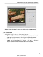
Figure 8-28. The Motion Presets panel gives you more than two dozen stock motion paths.
Applying the motion preset automatically inserts a motion tween on the lunatic’s layer, and then adds
the relevant property keyframes to reproduce the animation in question. If you chose
bounce- smoosh,
as we did, you’ll need to move the whole motion path upward to keep the symbol from bouncing and
smooshing off the bottom of the stage.
4. Using the Subselection tool, click the motion path, and then use the Align panel to center the
animation vertically on the stage.
As you may have guessed, it’s just as easy to apply the same (or different) motion preset to the other
symbol, but we would like to draw your attention to a related feature instead. That related feature is
that motion paths can be edited, or created completely from scratch, and then saved to the
Motion
Presets
panel. How? Glad you asked.
5. Shorten the duration of the lunatic’s animation by dragging
the right edge of the tween span slightly to the left. In our file,
we shortened the tween span from 75 frames to 50. Drag the
playhead to one or more of the property keyframes and use
the
Property inspector, Transform panel, or Free Transform tool
to alter the symbol’s antics along the existing motion path.
6. Click the tween span and, in the Motion Presets panel, click
the
Save selection as preset button ( Figure 8-29). You’ll be
prompted to give the new preset a name. Enter whatever you
like (we used
bounce-smoosh- alt) and click OK. Scroll to the
Custom Presets folder to find your preset.
The other buttons in the
Motion Presets panel let you create new fold-
ers and delete folders or presets.
Naturally, you could select the
big cheese symbol and apply your
newly minted custom preset, but there’s another way you can share
motion paths.
Figure 8-29. Motion paths,
whether made from scratch or
based on presets, can be saved
for later reuse.
389
ANIMATION, PART 2
7. Right-click (Ctrl- click) the lunatic’s tween span and select Copy Motion from the context menu.
Now right- click (Ctrl- click) frame 1 of the cartoon mouse’s layer and select
Paste Motion.
Because you used the
Align panel to change the position of the original motion path, you’ll need to do
the same for the copied path, assuming you want the lunatic and the cartoon mouse to fall in sync. It’s
easy as pie. While you could certainly use the
Edit Multiple Frames workflow discussed in Chapter 7—that
does still work here—you’ve learned in this chapter that motion tweens can be repositioned by way of
their motion paths.
8. Using the Subselection tool, click the cartoon mouse’s motion path to select it. Use the Align
panel, again, to center the animation vertically to the stage.
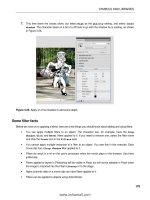
9. Preview the animation. You’ll see that both symbols perform the same movements (see
Figure 8-30).
Figure 8-30. Motion paths can be shared even without the Motion Presets panel.
That’s impressive enough, but let’s redo the last demonstration in a more dramatic way. These last few
steps should drive home the notion that, in Flash CS4, motion tweens—specifically, motion paths—are
entities that stand on their own, distinct from the symbol.
10. Select the lunatic symbol at any point along its tween span and delete the symbol.
When you delete the symbol, the tween span remains, along with all its property keyframes. Visually
speaking, the only difference in the tween span is that its first frame, usually a black dot, is now an
empty white dot.
11. Click the empty tween span to select it.
12. Drag a copy of the big cheese symbol from the library and drop it somewhere on the stage.
Location doesn’t matter—it can even be on the right side of the existing cheese thief.
390
CHAPTER 8
Because you selected the tween span first, the symbol will immediately adopt that span’s motion path
when you release the mouse to drop the symbol. You can’t do that with a classic tween!
Inverse kinematics (IK)
In one of the happiest sequences in Disney’s 1940 classic, Pinocchio, the wooden- headed puppet, once
freed from the apparatus that formerly helped him move, bursts into song, proudly declaring, “I got
no strings on me!” In Flash CS4, the authors suspect that you, too, will burst into song—but for the
opposite reason—when you see the tools for a new feature called inverse kinematics (IK).
What is this academic, vaguely sinister- sounding term? In simple words, IK lets you string up your art-
work like a train set, like sausages, or, if you prefer, like a marionette. And when you pull the strings, so
to speak, or move one of the connected symbols, your artwork responds like a bona fide action figure.
You can use IK to make poseable models, and then animate them.
Seriously, this feature is way cool, and we think you’re going to love playing with it. That said, it’s one
of the more complicated feature sets in Flash CS4. Stringing up your symbols is easy enough. The
official terminology calls for creating an armature and populating it with bones, which can then be
dragged around. Adobe engineers have made this dead simple.
The tricky part is a question of how. To a certain extent, you’ll find armatures and bones immediately
intuitive, but just when you think they make sense, they’ll behave in a way that might just strike you
as utterly wrong. You’ll see what we’re talking about in the following exercises, and we’ll show you an
approach that should give you what you expect.
It all starts with something called the
Bone tool.
Using the Bone tool
New (and very shiny!) to Flash CS4, the Bone tool is your key to the world of poseable armatures in the
authoring environment. Using it will give you an inkling of the satisfaction experienced by a certain
famous Victor Frankenstein, without anywhere near the hassle he went through or the illegal outings.
You won’t be visiting any actual graveyards, for example.
Let’s see how the
Bone tool works.
1. Open the >kjao*bh] file from the Atan_eoa folder for this chapter. You’ll be greeted by a more
or less anatomically correct hand, sans flesh (see Figure 8-31). Go ahead and wave! The wrist and
hand bones are all part of the same graphic symbol, named
hand in the library. The knuckles are
also graphic symbols, named by finger and knuckle number—for example,
ring1, ring2, and ring3.
All of these symbols happen to be on the same layer, but that doesn’t need to be the case.
2. Select the Bone tool from the Tools panel. It’s the one that looks like a bone, just above the
Paint Bucket. Click over the bottom- center portion of the skeleton’s wrist and drag toward the
bottom of the thumb’s first knuckle, as shown in Figure 8-32. When you release the mouse,
you’ll see your very first armature, which includes a single IK bone.
391
ANIMATION, PART 2
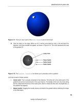
Figure 8-31. The Bone tool lets you connect symbols the way bones are connected in real life.
Notice the new layer in the Timeline panel, called Armature_1. That’s your armature, and as you con-
tinue to connect your symbols together with IK bones, those symbols will automatically be pulled to
this new layer. Just like a motion tween layer, this layer has distinctive properties. For example, you
can’t right- click (Ctrl- click) an armature layer to tween it, even though IK poses can be tweened (more
on this later in the chapter, in the “Animating IK poses section”). You can’t draw shapes on or drag
symbols to an armature layer.
Bones have two ends, and it’s helpful to know their anatomy. The larger end of the bone, where you
started to drag, is called the head. The smaller end of the bone, where you released the mouse, is
called the tail. The tail is pointing up and to the left in Figure 8-32. A string of connected bones is
called an IK chain or a bone chain.
Figure 8-32. Drawing your first bone
creates the armature.
392
CHAPTER 8
3. Hover somewhere inside the symbol that represents the first knuckle. You don’t need to be
exact—just within the symbol’s bounding box. Then click and drag toward the bottom of the
second knuckle. You’ll notice that even if you don’t begin the second drag directly over the tail
of the first armature bone, Flash will automatically snap it into place for you. Release when
you’re over the bottom of the second knuckle.
4. To finish the thumb, hover anywhere inside the sec-
ond knuckle’s symbol. Click and drag upward to the
bottom of the third knuckle. When you release, you’ll
have the simple bone rigging shown in Figure 8-33.
If you’re anything like the authors, you’re just dying to try out
these bones, so let’s take a quick break and do just that.
5. Switch to the Selection tool, grab that third knuckle,
and give it a shake.
We fully expect you’ll have fun, but all the same, you’ll also
see that it’s pretty easy to arrange the hand into what looks
like the result of a very painful accident (see Figure 8-34).
It may surprise you, for example, that the wrist pivots, and
those knuckles are bending into contortions that make even our yoga buddies wince. We’ll fix those
issues in just a moment. First, let’s get acquainted with the
Bone tool properties.
Figure 8-34. Ouch! Bones are easy to connect,
but the results aren’t always what you might
anticipate.
Bone tool properties
There are two ways to nudge the Property inspector into showing bone- related properties: by clicking
an IK bone on the stage and by clicking the armature itself, which is represented by a layer. Let’s start
with the armature.
Figure 8-33. As you connect symbols
with bones, the symbols are pulled to
the armature layer.
393
ANIMATION, PART 2
1. Continuing with the >kjao*bh] file, click frame 1 of the Armature_1 layer. When you do, the
Property inspector updates to show two twirlies:
Ease: In this area, you’ll find a drop- down list for selecting easing from a list of prebuilt
choices, and a
Strength value that lets you specify intensity, just as you saw in the Property
inspector
for motion tweens. These settings configure easing for the span of an armature
layer (you can drag out an armature span to encompass as many frames as you like).
Armature layers provide their own tweening capability, which is discussed in the “Animating
IK poses” section and again in the last exercise of this chapter. For now, just note that this is
where you can apply easing.
Options: The area gives you something to see even without tweening. The Style drop- down
list lets you specify how you want the IK bones to look. You have three choices:
Solid (the
default),
Wire, and Line, which are illustrated in Figure 8-35 from left to right. When working
with numerous or very small symbols, consider using the
Wire or Line styles. Why? Because
the
Solid view can obscure symbols that appear under the IK bones.
Figure 8-35. Bones can be configured as Solid, Wire, and Line (from left to right)
2. Change the Type drop- down selection from Authortime to Runtime. You’ll see the warning mes-
sage shown in Figure 8-36.
Figure 8-36. Only movieclip bones can be interactive at runtime.
The reason for the warning is that, although bones can be made interactive for the user, Flash requires
that the boned symbols be movieclips when
Type is set to Runtime. Fortunately, this is easy to change
in Flash CS4, even if there are numerous symbols in play.
3. Click OK to close the warning dialog box.
4. Open the library and click the first symbol, named hand, to select it. Press and hold the Shift
key, and then select the last symbol. Now everything in your library is selected.
5. Right- click (Ctrl- click) any one of the symbols and choose Properties from the context menu.
394
CHAPTER 8
What you get is a feature new to Flash CS4, which is an incredible time- saver. The
Symbol Properties
dialog box opens—not just for the symbol you clicked on, but for all selected symbols.
6. In the Symbol Properties dialog box, place a check mark in the Type property and change the
drop- down choice to
Movie Clip, as shown in Figure 8-37. Then click OK.
Figure 8-37. Flash CS4 lets you change multiple symbol
properties at once in the library.
All of your library’s graphic symbols become movieclips simultaneously. This used to take a separate
visit to each asset. However, you still need to let the stage know what you’ve done.
7. Click the stage to select it. Select Edit ° Select All. In one swoop, you just selected all your
symbols on the stage.
8. Click any one of the symbols to update the Property inspector, and then select Movie Clip from
the drop- down list at the top of the
Property inspector.
9. Click frame 1 of the Armature_1 layer and change the Type drop- down selection to Runtime.
10. Test the movie and wiggle those thumb knuckles inside Flash Player. Pretty neat!
11. Close the SWF and click one of the IK bones to update the Property inspector.
Now you see bone- specific properties. Let’s go over those:
Position X, Y, Length, and Angle: These are read- only properties, which means you can look, but
don’t touch. Thankfully, the names are self- explanatory.
Speed: Think of this as friction, or how much “give” the selected bone has in the armature.
A higher number means faster movement, and your range is
0 (no movement) to 200 (fast
movement).
Joint: Rotation: Here, you have the following choices:
Enable: Selecting this check box allows the bone to pivot around its head. In contrast, dese-
lecting it means the bone won’t act like a hinge.
Constrain, Min, and Max: Selecting Constrain activates the Min and Max hot text values, which
allow you to determine how wide an arc your hinge can pivot on.
395
ANIMATION, PART 2
Joint: X and Y Translation: The choices for this property are as follows:
Enable: Selecting this check box allows the bone to effectively pop in and out of its socket,
in either the x or y axis.
Constrain, Min, and Max: Selecting Constrain activates the Min and Max hot text values, which
allow you to determine how far the bone can move.
Of the properties available,
Rotation and Translation will give you the biggest bang for the buck. Let’s
see how easy it is to fix that misshapen hand! While we’re at it, you’ll learn some helpful subtleties on
manipulating the symbols in an armature.
Constraining joint rotation
IK bone rigs are as much an art as a science. The science facet derives from the Property inspector,
which gives you have some configuration settings. The art facet depends on your sense of the appro-
priate range of motion for a given armature. Let’s jump in:
1. Continuing with the >kjao*bh] file, use the Selection tool to drag the hand itself—not any of the
fingers or the thumb—and carefully pivot the hand so that it realigns again under the fingers.
2. Select the first IK bone (the one closest to the wrist) and deselect the Enable check box in
Property inspector’s Joint: Rotation area.
3. Drag the thumb’s third knuckle again, and note that the wrist no longer moves.
If you ever change your mind, just reselect the first IK bone and put a check mark back in the
Enable
property. Now let’s make sure the thumb doesn’t look so double- jointed.
4. Select the second IK bone and, in the Property inspector, enable the Constrain check box in the
Joint: Rotation area, as shown in Figure 8-38.
Figure 8-38. The Constraint check box lets you constrain a joint’s range
of motion.
Choosing Constrain adds a new component to the IK bone, which you can see in Figure 8-39. Suddenly,
the bone’s head sprouts a wedge shape, with a line in the middle that separates the wedge into two
pie pieces. The line has a square handle on its outside end. (If you’re in a Robin Hood mood, it may
look like a bow and arrow.) This wedge represents the joint’s range of movement. By default, you get
a 90- degree sweep.
396
CHAPTER 8
Figure 8-39. Select Constrain in the
Joint:Rotation area of the Property
inspector, and joints sprout a
range-of- movement icon.
5. Drag the third knuckle downward. The line with the square handle moves counterclockwise
until it rests against that side of the wedge. Drag the knuckle up, and the handle moves to the
other side—clockwise—until it meets the opposite side of the wedge.
Adjusting this range of movement is easy. The workflow we prefer is to pivot the IK bone into position
first, and then scrub the
Min or Max hot text as necessary to meet that position.
6. Drag the third knuckle upward until the thumb moves as far in that direction as you like. If
you need more room, select first knuckle’s IK bone and scrub the
Max value toward the right
to increase its value. Readjust the thumb, and when you like how it sits, scrub the
Max value
toward the left again to bring the edge of the wedge toward the square- handled line.
7. Drag the third knuckle all the way down and repeat this process for the other extreme. You’ll
notice that the first knuckle appears above the bones of the wrist, as shown in the left side of
Figure 8-40. That may or may not be what you want. If you want to send the knuckle behind
the wrist, use the
Selection tool to select that knuckle’s symbol and select Modify ° Arrange °
Send to Back
. The results will look like the right side of Figure 8-40.
Figure 8-40. Use standard layer stacking to move symbols above (left)
or behind each other (right).
397
ANIMATION, PART 2
The first knuckle is done. You can now move onto the second, which isn’t any harder to manage.
8. Add a Joint: Rotation constraint to the second knuckle and configure the Min/Max values in
whatever way suits you.
As you move the skeleton bones around, you can use the Shift key to temporarily change the way the
IK bones respond. For example, drag the third knuckle up and down, and then hold down Shift and
drag again. When Shift is pressed, only the third knuckle moves. This works with any other bone. Drag
the second knuckle with and without Shift to see what we mean.
While you’re at it, experiment with the Ctrl (Cmd) key as well. If you ever want to reposition a symbol
without having to redo an IK bone from scratch, hold down Ctrl (Cmd) while you drag. This temporarily
releases the dragged symbol from its IK chain. When you release the key, the IK bones are reapplied.
The third knuckle is the interesting one, because although it’s attached to an IK bone, it’s only associ-
ated with that bone’s tail. This means you can’t constrain its rotation. (Give it a try!) So what to do?
Since we’re dealing with so many kinds of bones, we think it’s fitting that the answer relies on the
presence of a ghost. Not a real ghost, of course, but a stand- in “ghost” movieclip.
9. In the Timeline panel, select the nonarmature layer (the one labeled bones).
10. Use the Oval tool to draw a small circle—say, 20 pixels 20 pixels—no stroke, and color
doesn’t matter.
11. Convert that circle to a movieclip. Name the symbol ghost handle, and position it just past the
thumb’s third knuckle.
12. Using the Bone tool, add a fourth IK bone between the
third knuckle and the
ghost handle movieclip, as shown in
Figure 8-41.
13. Select the newest IK bone and constrain its Joint: Rotation
property.
14. Save your file.
Sure, the “ghost” movieclip may look a little silly, but its presence
allows you to configure your IK bones from start to finish.
Here’s the best part: whenever you need another stand- in IK bone,
make sure to keep reusing that same
ghost handle movieclip. Why?
Because when you’re ready to publish the SWF, all you have to do is
open that symbol in the library and change its fill color to
0% Alpha.
Just like that, your extra handles become invisible, and they still do their job.
Deleting bones
We showed you how to create IK bones, but you’ll also want to know how to delete them. It couldn’t
be easier:
1. After saving your >kjao*bh] file, use the Selection tool to select the fourth IK bone from the
previous exercise. Press the
Delete key. Badda bing, badda boom . . . the bone is gone.
2. Skip the third IK bone and select the second one. Press the Delete key.
Figure 8-41. Use a stand- in movieclip
to let you constrain the previously
end-of-the- line IK bone.
398
CHAPTER 8
This time, both the second and third bones disappear. This tells you that deleting an IK bone automati-
cally deletes any other bones attached to its tail.
3. Right-click (Ctrl- click) frame 1 in the Armature_1 layer and select Remove Armature from the
context menu.
As expected, the last IK bone disappears. If you had made this selection in step 1, all of the IK bones
would have disappeared from the start.
4. Select File ° Revert, and then click the Revert button in the alert box to undo all the deletions.
Applying joint translation
Another way to control the movement of joints is called joint translation. This affects movement of an
IK bone along its x or y axis (or both). To illustrate, we’ll leave our skeleton at the chiropractor’s for
a while and turn our attention to a rudimentary steam engine.
1. Open the Opa]iAjceja*bh] file from the Atan_eoa folder for this chapter. The symbols are
already in place for you.
In Figure 8-42, we’ve labeled the engine’s anatomy to assist you in the next steps, so you can focus
your attention entirely on the IK rigging. You’re going to connect three horizontal symbols from left to
right. Ignore the wheel for the time being.
Figure 8-42. The movement of this steam engine will include joint translation.
2. Select the Bone tool, and then add a bone that starts on the left side of the piston rod symbol
and ends on the
crosshead bearing symbol (the center symbol).
3. Add another bone from the crosshead bearing symbol to the right side of the connecting rod
symbol, as shown in Figure 8-43. This is no different from the bone rigging you did for the
knuckles.
399
ANIMATION, PART 2
Figure 8-43. Two bones connect three symbols.
Joint translation doesn’t require ActionScript, but we’re going to use some programming to demon-
strate it in this particular case. Because we’ll be using ActionScript, let’s give the bones and armature
meaningful instance names.
4. Using the Selection tool, select the right- hand bone and use the Property inspector to give it the
instance name
connectingRod, as shown in Figure 8-44.
Figure 8-44. Bones and armatures support instance names, just like movieclip symbols.
Pay close attention to the Property inspector when making your selections. It’s easy to
accidentally click the symbol to which a bone is applied, rather than the bone itself. In
this context, the symbol is listed as an
IK Node in the Property inspector. If you select
an IK node, this exercise won’t work properly. Figure 8-44 shows the correct selection of
a bone, which displays
IK Bone in the Property inspector.
400
CHAPTER 8
5. Select the other bone and give it the instance name pistonRod.
6. Select the armature itself by clicking on frame 1 of its layer in the Timeline panel. Use the
Property inspector to give the armature the instance name engine. The armature’s layer name
will update to the same name.
Now it’s time for the joint translation, but first, let’s keep this bone from rotating. It’s possible for
bones to translate and rotate, but that isn’t what we want here. Our aim is to let the piston rod slide
left and right when the armature moves.
7. Select the pistonRod bone and use the Property inspector to disable its rotation (that is, deselect
the
Enable check box in the Joint: Rotation area).
8. To achieve the left-and- right motion, select the Enable check box in the Joint: X Translation area.
The bone’s head gets a horizontal double- headed arrow, as shown in Figure 8-45.
Figure 8-45. Joint translation is indicated by a double- headed arrow along the relevant axis.
You could optionally constrain this translation by selecting the Constrain check box and configuring
Min and Max values, just as with joint rotation, but that isn’t necessary here. Note, too, that you could
optionally translate (and constrain) along the y axis, but we’ll also omit that step.
Time to get this steam engine moving!
9. Click frame 1 of the armature’s layer (engine) to select the armature. In the Property inspector’s
Options area, change the Type drop- down selection to Runtime. Now this rigging is ready for
ActionScript.
10. Select frame 1 of the scripts layer and open the Actions panel. Type the following
ActionScript:
eilknpbh*eg*&7
r]nlp6Lkejp9jasLkejp$%7
r]n]ni6EG=ni]pqna9EGI]j]can*cap=ni]pqna>uJ]ia$ajceja%7
r]n^kja6EG>kja9]ni*cap>kja>uJ]ia$_kjja_pejcNk`%7
401
ANIMATION, PART 2
r]np]eh6EGFkejp9^kja*p]ehFkejp7
r]nlko6Lkejp9p]eh*lkoepekj7
r]neg6EGIkran9jasEGIkran$p]eh(lko%7
The first line imports all the classes in the bh*eg package, which includes classes necessary for identi-
fying and manipulating armatures created in the authoring tool. The next line declares a variable, lp,
set to an instance of the Lkejp class. (The Lkejp class doesn’t reside in the bh*eg package, but in just
a moment, you’ll see that something called the EGIkran class needs a Lkejp instance.)
From the third line on, the code unfolds like the lyrics in that old catchy tune, “Dry Bones” (“the
knee bone’s connected to the . . . thi-i- igh bone”). How so? A variable, ]ni, is declared and set to an
instance of the EG=ni]pqna class. This variable takes its value from a method of the EGI]j]can class,
which connects it to the armature whose instance name is ajceja.
After that, a ^kja variable—an instance of the EG>kja class—is connected to the bone whose instance
name is _kjja_pejcNk`. Then a p]eh variable (EGFkejp class) is connected to the p]ehFkejp property
of the ^kja instance. Finally, a new Lkejp instance (lko) is connected to a pair of coordinates from the
lkoepekj property of the p]eh instance.
The p]eh and lko variables are passed as parameters to a new instance of the EGIkran class, which is
stored in the variable eg. That eg variable is what allows you to move the armature with code.
11. Add the following new ActionScript after the existing code:
sdaah*]``ArajpHeopajan$Arajp*AJPAN[BN=IA(olej%7
bqj_pekjolej$arp6Arajp%6rke`w
sdaah*nkp]pekj'917
lp*t9sdaah*_n]jg*t7
lp*u9sdaah*_n]jg*u7
lp9sdaah*hk_]hPkChk^]h$lp%7
eg*ikraPk$lp%7
y
The basic premise here is something you’ve already seen in other chapters: a custom function, olej$%,
is associated with the Arajp*AJPAN[BN=IA event of an object with the instance name sdaah. In this
case, sdaah is the instance name of the wheel- shaped movieclip symbol. (We’ve already configured
the instance name for you in the sample file, and the
wheel symbol contains another movieclip inside
it with the instance name _n]jg.)
So what’s going on in this event handler? First, the Ikrea?hel*nkp]pekj property of the sdaah instance
is incremented by five. That gets the wheel rolling continuously. After that, it’s just a matter of updating
the lp variable declared earlier. Being an instance of the Lkejp class, the lp variable has t and u proper-
ties, which are set to the
crank movieclip’s t and u properties, respectively. Because _n]jg resides inside
sdaah, the object path to the desired t property is sdaah*_n]jg*t. The same goes for u.
This updates lp’s properties to the current position of _n]jg, but that isn’t quite enough. From the
wheel symbol’s point of view, _n]jg never actually moves—it’s sdaah that does the rotating!—so the
coordinates need to be considered from the point of view of the stage. That’s what the second-to- last
line does by invoking the @eolh]uK^fa_p*hk_]hPkChk^]h$% method on the sdaah instance. In plain
English, it tells lp to reset itself in from _n]jg’s local coordinates inside sdaah to the _n]jg’s global
coordinates shared by all objects on the stage.
402
CHAPTER 8
Finally, lp is passed as a parameter to the EGIkran instance represented by the eg variable.
12. Test your movie so far to see the result.
It’s close to being correct, and the leopkjNk` bone does perform its horizontal joint translation, but
if you look carefully, you’ll notice that the armature occasionally “slips” from the crank movieclip, as
shown in Figure 8-46. That’s easy to fix, and it’s nothing more than a matter of priorities.
Figure 8-46. The armature isn’t always fast enough. This is easy to fix.
The armature isn’t updating as quickly as the wheel turns, so let’s fix that by limiting the number of
calculations it has to make.
13. Use the Actions panel to insert the following two lines after the eg variable declaration and the
event listener (new code shown in bold):
***
r]neg6EGIkran9jasEGIkran$p]eh(lko%7
eg*heiep>uEpan]pekj9b]hoa7
eg*epan]pekjHeiep917
sdaah*]``ArajpHeopajan$Arajp*AJPAN[BN=IA(olej%7
bqj_pekjolej$arp6Arajp%6rke`w
***
14. Test the movie again, and everything should run fine.
A note about bone preferences
Let’s return to our friendly skeleton hand. We mentioned earlier in this chapter that IK poses can be
animated, even without the use of a motion tween layer. You’ll see how in the next section. First, it’s
time for a quick field trip.
1. Open the >kjaoNecca`*bh] file in this chapter’s Atan_eoa folder. You’ll see the fingers and
thumb pointing upward, and the thumb has a ghost handle.
403
ANIMATION, PART 2
2. Use the Selection tool or the Free Transform tool to click the first knuckle of the pointer finger.
As Figure 8-47 shows, the symbol’s transformation point (the small white circle) is dead center.
Figure 8-47. This symbol’s
transformation point is
horizontally and vertically
centered.
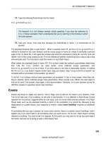
3. Noting the transformation point, select Edit (Flash) ° Preferences and click the Drawing choice
in the
Category area. Find the IK Bone tool: Auto Set Transformation Point check box and deselect
it, as shown in Figure 8-48. Click
OK to close the Preferences dialog box.
Figure 8-48. The Auto Set Transformation Point setting affects how bones
are applied to symbols.