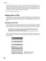
Foundation Fireworks CS4- P3 ppsx
Bạn đang xem bản rút gọn của tài liệu. Xem và tải ngay bản đầy đủ của tài liệu tại đây (4.03 MB, 30 trang )
39
WORKING WITH BITMAPS
Figure 3-10 shows the Pencil tool’s Property inspector settings.
Figure 3‑10. Pencil tool settings
The following list details each of the Pencil tool settings:
Color: Specifies a color for the Pencil tool.
Anti-aliased: Toggles between a hard or smooth line.
Auto erase: Uses the fill color instead of the stroke color.
Preserve transparency: Prevents the Pencil tool from drawing in transparent areas of the bitmap.
You can only draw on existing pixels.
Opacity: Allows you to adjust the opacity of the drawn pixels from 0 (transparent) to 100%
(opaque).
Blend mode: Allows you to use any one of the 46 built- in blend modes. These blend modes
contain all of the built- in Photoshop blend modes and consist of effects like
Darken, Lighten,
Overlay, Difference, Hue, Reflect, Additive, Invert, and Erase.
Create straight lines or polygons by holding down the Shift key while drawing with the
Pencil tool. Click once to set the start point, and then continue to click in other areas
of the bitmap to create straight lines between the points.
Quickly select colors from the canvas by holding down the Alt key while the
Pencil tool
is active. You will temporarily switch to
Eyedropper mode. Click to select a new color,
and then release the Alt key to return to
Pencil mode.
Brush tool
The Brush tool uses Fireworks’ built- in brushes to allow you to paint with tips other than a single fine
line. These brushes range from a solid hard line to randomly sized and oriented patterns that change
in opacity depending on how fast or slow you move your mouse. To use the
Brush tool, press the B key
until the
Brush tool icon is highlighted in the Tools panel. Figure 3-11 shows some of the many brush
tips that can be used.
40
CHAPTER 3
Figure 3‑11. Sample brush tips
Unlike the Pencil tool, the Brush tool includes a number of options that you can configure using the
Property inspector, as shown in Figure 3-12.
Figure 3‑12. Brush tool settings
The following list details these settings:
Color: Allows you to specify a color for the brush.
Tip size: Increases or decreases the diameter of the brush tip from 1 to 100 px.
Stroke category: Lets you select one of the 54 available brushes. In Figure 3-12, Soft Rounded is
selected.
Edge softness: Adjusts the softness of the brush tip’s edge from 0 (hard) to 100 (soft).
Texture: Selects a texture to apply to the drawn pixels. You can choose from one of 52 built- in
textures. These textures range from grids to dots to lines, to organic textures like burlap and
smoke. You can even load an external image for use as a custom texture.
Amount of texture: Changes the amount of texture applied from 0 to 100% opacity.
41
WORKING WITH BITMAPS
Most of the brush tips are speed sensitive, meaning their properties vary depending on
how fast you move your mouse while drawing.
Hold the Shift key while drawing to constrain the brush in straight lines at 45 degree
increments.
Hold the Shift key and click different portions of the canvas to draw straight lines
between the points.
Eraser tool
The Eraser tool, as its name implies, is used to erase pixels from a bitmap layer. Like the Brush tool,
the
Eraser tool lets you adjust its tip size, edge softness, shape, and opacity. Using the settings shown
in Figure 3-13, you can precisely and subtly remove unwanted areas of your bitmap.
Figure 3‑13. Eraser tool settings
Image adjustment/effects tools
The next set of tools is used to apply subtle effects or adjustments to your bitmap layers. The first two,
Blur and Sharpen, work hand in hand, letting you soften or sharpen areas of your image. The next two,
Dodge and Burn, let you lighten or darken areas of your image. The third tool, Smudge, lets you push
pixels of your image almost as if you were finger painting.
Blur and Sharpen tools
The Blur tool is often used to soften or blur the focus of areas in your image. You can cover up imper-
fections in a skin by lightly blurring them as well. Alternatively, you can sharpen the edges of objects in
your images using the
Sharpen tool. This can be useful if you have a photo that is slightly out of focus
that you want to add some clarity to. It may not bring your best friend’s face into focus, but it can
make your flower shot look a little more professional. Both of these tools share the same settings in
the Property inspector, as shown in Figure 3-14. These settings should look familiar by now, as you’ve
seen them in the Property inspector for previous tools.
42
CHAPTER 3
Figure 3‑14. Blur and Sharpen tool settings
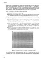
In Figure 3-15, the first letters of the words “SHARPEN” and “BLUR” have been modified using the
Sharpen and Blur tools, respectively.
Figure 3‑15. Effects of the Sharpen and Blur tools on text edges
Notice the edges of the “S” in “SHARPEN.” It should look more pixilated to you. Likewise, the edges
of the “B” in “BLUE” are softer than those of the other characters. Together, these tools can help you
refine a not-so- perfect bitmap, whether the contents of that bitmap are vector art or text, or a slightly
out-of- focus photo.
Dodge and Burn tools
The Dodge and Burn tools can be used to lighten and darken areas of your image, respectively. Together,
these tools can enhance photographs, bringing out areas in shadows and darkening areas that have
been washed out. Figure 3-16 shows the settings for the Property inspector for these two tools.
Figure 3‑16. Dodge and Burn tool settings
43
WORKING WITH BITMAPS
In addition to the familiar Size, Edge, and Shape settings, both Dodge and Burn tools include Range
and
Exposure settings. Use the Range setting to select a color range to target with the current tool:
Shadows: Targets dark areas of the image
Highlights: Targets light areas of the image
Midtones: Targets the middle range per channel of the image
The
Exposure value is similar to the Amount value in previous tools. Adjust this setting to affect how
strongly the dodge or burn effect is applied.
The photo shown in Figure 3-17 was taken at sunset. Getting the exposure right for both the light-
house in the foreground and the sky in the background always proves a difficult task.
Figure 3‑17. Bringing out the details of an image using Dodge, Burn,
and selection tools
We’ve masked the body of the lighthouse and started to lighten the tower using the Dodge tool. You
can see the effects of the tool at the bottom of the tower where we haven’t completed painting. With
a little patience, the
Dodge and Burn tools, along with some precise masking, can really enhance the
quality of your photos.
44
CHAPTER 3
Smudge tool
Use the Smudge tool to subtly blend colors or create more dramatic melted or finger painted looks.
Like the previous tools, you can adjust the
Size, Edge, Shape, and Pressure settings of the Smudge
tool, as shown in Figure 3-18.
Figure 3‑18. Smudge tool settings
In addition to these common settings, you can enable the Smudge color option. When enabled, the
smudge will start with the color you specify. The result is like working with a combination of the
Brush
tool and the
Smudge tool. You can also enable Use entire document. When this option is checked,
colors from all layers in the document will be used in the smudge, but they will continue to be drawn
on the active bitmap layer.
Additional retouching tools
The final set of bitmap tools are used for retouching areas of your image by either cloning pixels,
replacing colors, or removing red- eye from your photos.
Rubber Stamp tool
The Rubber Stamp tool is great for fixing blemishes on photographs or even creating seamless tex-
tures. To use the
Rubber Stamp tool, press the S key until the Rubber Stamp tool is highlighted in the
Tools panel. Now, hold down the Alt key and click any existing bitmap layer or object to set your tar-
get clone area. Once you’ve selected your target area, continue holding Alt and position your cursor
where you want to start cloning pixels. When you have your cursor positioned, release the Alt key and
begin drawing. Figure 3-19 shows the
Rubber Stamp tool settings.
Figure 3‑19. Rubber Stamp tool settings
In addition to Size and Edge settings, which adjust the size and softness of the brush, you can enable
the
Source aligned property. When enabled, the source location remains fixed as you perform multiple
paint operations. When deselected, the source area moves relatively with the cursor. This is one of
those features that is really difficult to describe, so to fully understand the effects of this property, you
45
WORKING WITH BITMAPS
really need to experiment with it yourself. Figure 3-20 demonstrates how the Rubber Stamp tool can
be used to remove unwanted areas of an image.
Figure 3‑20. Using the Rubber Stamp tool to remove areas of an image
We were quickly able to paint out the rivets of this sign without masking the image at all.
Replace Color tool
The Replace Color tool is almost like a hybrid between the Magic Wand tool and the Brush tool. You
can select a target color, specify
Tolerance and Strength values, and then paint over the target color
with a selected color. Using the
Replace Color tool, you can paint individual flowers, change a shirt
color, or create any number of effects. Figure 3-21 shows the Property inspector settings for the
Replace Color tool.
Figure 3‑21. Replace Color tool settings
You can specify a replacement color either by specifying a color swatch or by clicking the target color
you want to replace. Choose
Swatch from the From combo box to select a specific replacement color,
and then select a color from the first color box. When you start painting, only pixels similar to the
color you set in the color box will be altered. If you select
Image from the From combo box, the first
color you click when you start painting will become the target color. This is a faster method, but it may
46
CHAPTER 3
not be as precise as selecting a single target color. Adjust the Tolerance setting like you would for the
Magic Wand tool. The higher the value is, the greater the range of colors that will be replaced.
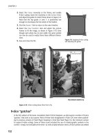
In Figure 3-22, we used the
Replace Color tool to change the paint color of the background wall.
Figure 3‑22. Changing the wall color with the Replace Color tool
In this example, we just used the Replace Color tool, and you can see that the results are quite good.
For a true production- quality modification, we would probably mask some of the more difficult areas
to ensure that our new color doesn’t bleed into any unwanted areas.
Red Eye Removal tool
The Red Eye Removal tool is perhaps the easiest of the bitmap tools to work with. You simply draw a
rectangle around the red- eye in your photo, and Fireworks takes care of the rest. The Property inspec-
tor settings for this tool, shown in Figure 3-23, offers
Tolerance and Strength adjustments that can be
used to tweak the tool quickly.
Figure 3‑23. Red Eye Removal tool settings
Figure 3-24 shows the effectiveness of the Red Eye Removal tool. On the left is a photo exhibiting typi-
cal red- eye symptoms. On the right is the same photo after processing. Two simple rectangles are all
it takes to restore balance to your world!
47
WORKING WITH BITMAPS
Figure 3‑24. Red Eye Removal tool results
Summary
The bitmap tools included in Fireworks cover all of your daily editing needs as an interface and web
designer. It’s only when you need to edit hi- res images, edit in CMYK, or perform sophisticated pro-
cessing and retouching of images that you need to turn to a tool like Photoshop. Using the
Path to
Marquee
and Marquee to Path commands is a great way to create precise selections or quickly create
vector artwork from bitmap artwork. Take the time to master the bitmap tools discussed in this chap-
ter, and your design workflow will be that much more streamlined!
Chapter 4
In this chapter, you will discover the world of vector graphics. You’ll discover how
vectors are different from bitmap objects, or raster objects, learn how to use various
tools to draw vector objects within Fireworks, and explore scenarios for using vectors
to achieve unique graphical effects.
One of the chief attractions of Fireworks is its prowess as a rapid prototyping appli-
cation. Fireworks provides easy-to- use drawing tools to create vector- based graphics
along with bitmap graphics. The ability to create vector- based graphics and modify
them on the fly right there within the prototyping tool gives Fireworks a distinct
advantage over its competitors.
Raster graphics are representations of images based on pixels. Because of this, raster
images lose clarity and become pixelated when resized, especially when enlarged.
Vector graphics are different from raster graphics in that a vector object is a math-
ematical description of an object. Vectors are created using geometric objects such
as points, curves, and lines based on mathematical computations to define their
shape and dimension. One distinct characteristic of vector images is they can be
scaled indefinitely without degrading, which makes them particularly useful for the
low- resolution demands of the Web.
WORKING WITH VECTORS
50
CHAPTER 4
Using the Vector tools
The Vector tools (see Figure 4-1) can be found in the main Tools palette. To save space in the main
palette, related tools are stacked, as indicated by the small down arrow next to certain tool icons. To
select a tool other than the one displayed, click and hold to display the tool options. Let’s take some
time to look at the vector drawing tools Fireworks provides and explore how these help us create
common graphics in everyday situations.
Figure 4‑1. The
Vector tools
section of the
Tools palette in
Fireworks CS4
Line tool
The Line tool is a very basic tool, and it does exactly what you think it does—it draws a line. The
Line tool will create a line in its truest sense—a straight line with a beginning point and an end-
ing point (see Figure 4-2). To draw a line, select the
Line tool from the Tools palette. Then, just
click and drag from the beginning point to where you want the endpoint of the line to be.
Figure 4‑2. A simple line drawn with the Line tool
50
51
WORKING WITH VECTORS
Holding down the Shift key while dragging will force the line to be perfectly straight.
With the Shift key pressed, moving the mouse around will snap the line segment to 45
degrees.
Because this line is drawn with vectors, it is fully editable. If you decide later that the line needs to be
longer, shorter, or moved to a different location, just use the
Subselection tool to select an endpoint
and move it either with the mouse or the arrow keys to the desired coordinates.
Pen tool
In other drawing programs, the Pen tool may be referred to as a Bézier tool. For us, the Pen
tool is the workhorse tool of the bunch—you can draw virtually any shape with it. Drawing
polygons with straight lines is easy, but you can also draw more organic shapes with curved
edges. The
Pen tool takes a lot of practice to be comfortable drawing with it, but once you’ve got the
hang of it, it is indispensible.
There are a couple different ways to handle the
Pen tool, and each has its own useful purpose. To
draw straight- edged shapes (a square, for instance), you click once to begin drawing a line, click again
at a different location to initiate the next point in the shape, and repeat until you get back to the
original point (see Figure 4-3). Fireworks has a couple of built- in helpers. First, it enables you to draw
a perfectly straight line by holding down the Shift key as you move your cursor. Second, it provides a
few visual cues to help you understand what will happen on your next click, such as whether your click
will close a path or add or subtract points.
Figure 4‑3. A simple straight- edged vector object
drawn with the Pen tool
51
52
CHAPTER 4
When you are using the Pen tool to draw a shape and are about to close it, the cursor changes to a
pen with a small circle, indicating your next click will complete that shape. Let’s say you have already
drawn a perfectly nice square, but you’d like to add a point. With your square highlighted and your
Pen tool selected, as you hover over any one of the segments of the square, the cursor changes to a
pen with a plus sign next to it, indicating that your next click will add a point. Conversely, hovering
over an existing point, your cursor changes to a pen with a minus sign next to it, which means clicking
there will remove that point from the shape.
You can also draw curves and organic shapes with the
Pen tool. This requires a slightly different
technique. Instead of clicking and moving the cursor to the next point, you click and drag the cursor,
which creates a curve using Bézier handles. These handles control the shape of the curve and can be
moved in tandem or alone for different effects (see Figure 4-4).
Figure 4‑4. A curved contour vector object drawn with
the Pen tool
Vector Path tool
Similar to the Line tool, the Vector Path tool (which you bring up by clicking the arrow beside
the
Pen tool) allows you to draw a line, but unlike the Line tool, it allows for more than just
straight lines. Straight lines, curved lines, even scribbled freeform lines can be drawn that will
be converted to a vector- based path (see Figure 4-5). The
Vector Path tool also allows you to “close
the loop,” creating a shape that can have a solid color fill. You can then edit any of the points along
the path to change the line.
53
WORKING WITH VECTORS
Figure 4‑5. A random line drawn with the
Vector Path tool
Rectangle tool
As mentioned previously, the small inverted trian-
gle next to any icon in the
Tools palette indicates
that other related tools are available but not shown.
To reveal these other options, just click and hold on the
icon, hover over the desired tool, and release the mouse
key to select that tool. The most common tools available in
addition to the default
Rectangle tool are the Ellipse and
Polygon tools. Selecting any one of these will allow you to
create the shape by clicking and dragging to the desired
dimensions. Holding down the Shift key while dragging will
force the tool to create an exact square or circle, depend-
ing on the tool selected. Other autoshape tools include the
Star, Arrow, Chamfer Rectangle, and so on (see Figure 4-6).
Notice in Figure 4-5 the diamonds (which will appear yellow
on your screen) associated with the star shape. Many of the
autoshapes contain these yellow diamonds, which are con-
figuration points. Each configuration point changes the
shape in some way. For example, by adjusting the roundness
configuration point, a star like the one in Figure 4-7 can be
changed to look like the stylized star in Figure 4-8.
Figure 4‑6. Drop- down revealing alterna-
tive autoshape tools
54
CHAPTER 4
Figure 4‑7. An ellipse, polygon, and star drawn with the autoshape tools
Figure 4‑8. A simple
star shape with the
roundness configuration
point adjusted
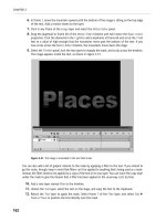
Text tool
The Text tool allows the creation of text boxes and gives the user a great deal of flexibility and
options when dealing with text in a Fireworks document (see Figure 4-9). The Property inspec-
tor shows all the different options for changing the properties of the selected text.
Figure 4‑9. The Text Properties panel
Everything from font selection and size to line height and justification is controlled in the Text
Properties
panel.
55
WORKING WITH VECTORS
Fireworks allows text to be converted to paths for further editing of letter
forms (see Figure 4-10). To convert text to paths, just select the text and
choose
Text ➤ Convert to Paths. Converting text to paths is a good idea in
certain situations. Perhaps you’re creating a graphic with text set in a par-
ticular typeface. You’d like to send the file to a colleague so he or she can
make further changes, but you know your colleague doesn’t have that
font installed on his or her system. Converting text to paths disassociates
the text from a specific font, making the letterform’s vector paths instead
of characters in a text box. Now your colleague can manipulate the text,
and you can be assured that the font you chose for the graphic is intact.
Or perhaps you are creating a graphic with text, but you need to modify
the look of the typeface. Since converting text to paths changes the char-
acters to individual vector objects, you have complete control over the
size, shape, and contour of each character.
When text is converted to paths, all the individual text characters are grouped into a
single group, and elements in the path objects cannot be converted back to text objects
apart from an undo.
Freeform and Reshape Area tools
The Freeform and Reshape Area tools, which are grouped, are very similar. Both tools allow a
path to be changed with the push of the cursor (see Figure 4-11). Select a vector shape, click
the path of the shape, and drag to “push” the element into a different shape, creating new
points and tangents along the path as needed. In the Property inspector, the size and pressure
can be adjusted for varying effect.
Figure 4‑11. An ellipse after a swipe of the Freeform tool
Figure 4‑10. Text that has been
converted to vector paths
56
CHAPTER 4
Knife tool
The Knife tool allows for the bisection (see Figure 4-12) of one or more paths of a vector
object, resulting in two separate and independent elements on the canvas.
Figure 4‑12. A triangle bisected with the Knife tool (shapes separated so you can see them)
Using the Paths panel
A vector shape is an outline that comprises different lines. The shape contains nodes, which define
the flexibility in editing the shape for its roundness. Each of these nodes can be modified indepen-
dently using the
Subselection tool. These individual nodes are used to modify the contour of the shape
created.
Some of the tools described previously are used to modify points, which in turn changes the shape of
the object. Fireworks provides several different ways of modifying points and paths. These different
means of modifying the complete vector path or individual points of the path can be found in two
menu items located at
Modify ➤ Combine Paths and Modify ➤ Alter Paths.
Apart from the menu locations, Fireworks CS4 makes accessing path modification options much easier
by combining them all in a special new
Paths panel (see Figure 4-13). They’ve also added several new
options that are accessible only from the
Paths panel. The Paths panel is located in the Workspace
panel, which appears on the right side of the canvas; alternatively, it can also be found by selecting
Window ➤ Others ➤ Path.
57
WORKING WITH VECTORS
Figure 4‑13. The Paths panel
Within Fireworks all the vector objects can finally be converted to the lowest level as a path. You
can see this for yourself by ungrouping vector shapes until the
Layers panel reflects the name of the
object as a path. Lines are paths by default when created using the
Pen tool.
The
Paths panel is organized into four different categories based on the type of effect you are trying
to achieve:
Combine Paths: This section contains functionality such as union, intersection, punch, and com-
bine that will work on the shapes as a whole.
Alter Paths: The commands within this area will modify the shapes for functionalities such as
extrude and blend.
Edit Points: The individual nodes in a vector shape can be manipulated through these functions.
Some of the functions present are smooth, straight, and sharp.
Select Points: This will allow for selection of nodes in the vector shape that can then be worked
upon using functionalities present in the
Edit Points section.
To demonstrate how paths and points can be combined, altered, and edited, let’s use two basic shapes
for our common example for each technique.
58
CHAPTER 4
Combining paths
While working with vectors, sometimes its necessary—and some-
times downright beneficial—to combine the paths of two separate
objects. For our examples, let’s use two different shapes—
an ellipse and a square (see Figure 4-14), each on a separate layer—
and overlap them to demonstrate the effects of combining
paths on two vector objects. We’ll use the same two shapes
throughout for consistency.
Apart from the
Paths panel, the options we’ll be exploring are
also available under the menu item
Modify ➤ Combine Paths.
However, using the panel provides ease of click execution com-
pared to submenu navigation and then function execution.
The following commands appear from left to right in the
Combine
Paths
section.
Note also that hovering over a particular tool in the Paths panel will bring up a tooltip
with that tool’s name.
The Join Paths command allows you make one vector shape out of two, which is different from
grouping the two objects. Joining their paths also “knocks out” the area where the two objects
overlap, as shown in Figure 4-15.
Split Paths will do the opposite of Join Paths. This command
can also be used by selecting
Modify ➤ Combine Paths ➤ Join.
Figure 4‑15. The Join Paths
command in action
Figure 4‑14. Two simple shapes,
slightly overlapping
59
WORKING WITH VECTORS
Selecting Union Paths actually makes one object with a new path that is made from the merg-
ing of the two objects (see Figure 4-16). While
Join Paths will knock out the overlapping areas,
Union Paths will not; instead it removes any extra points, merging the two objects together as
one. This command can also be used by selecting
Modify ➤ Combine Paths ➤ Union.
Figure 4‑16. The result
of using the Union Paths
command on our example
shapes
Intersect Paths allows you to make a single shape from the paths where the two other shapes
overlap, as shown in Figure 4-17. Selecting this tool removes the parts of the objects that are
not within the overlapping area. This command can also be used by selecting
Modify ➤ Combine
Paths ➤ Intersect
.
Figure 4‑17. Applying the
Intersect Paths command
to our circle and ellipse
gives us this shape.
Punch Paths also works with the overlapping area shared
between the two objects, functioning much like an
everyday cookie cutter. In this case,
Punch Paths uses the
object that is in front or on top per the hierarchical order
to cut into the shape below, thus redrawing the path
using the shape of the object in front and removing that
object (see Figure 4-18). The
Punch Paths tool relies on
layer order, so keep in mind which objects are in which
layers. This command can also be used by selecting
Modify ➤ Combine Paths ➤ Punch.
Figure 4‑18. The Punch Paths
command at work
60
CHAPTER 4
Divide Paths will create new shapes from two or more overlapping objects (see Figure 4-19).
The key here is the overlap. Any overlapping area gets divided into its own separate shape, in
addition to the areas outside the overlap.
Figure 4‑19. Our example
shapes after applying the
Divide Paths command
(with shapes separated for
easy viewing)
Exclude Paths is the inverse of Divide Paths. When two objects are overlapping and the Exclude
Paths
action is used, it will remove the overlapped area, resulting in two separate objects,
which were the areas outside the overlap (see Figure 4-20).
Figure 4‑20. The Exclude
Paths
command gives us
shapes outside an overlap-
ping area.
61
WORKING WITH VECTORS
Trim Paths will create two new and separate objects from the overlapping shapes. This is similar
to
Punch Paths in that it relies on layer order, but it does not remove any part of the objects
(see Figure 4-21).
Figure 4‑21. The results of
applying the Trim Paths
command to our example
shapes (with shapes sepa-
rated for easy viewing)
Crop Paths is similar to Intersect Paths in that Fireworks will keep only the shared area between
two overlapping objects (see Figure 4-22). This command can also be used by selecting
Modify
➤ Combine Paths ➤ Crop
.
Figure 4‑22. The Crop Paths command’s results are similar to those for Intersect Paths.
Altering paths
Within the Paths panel under the Alter Paths section are several options for modifying and adjusting
the path points of a specific object. Most of these tools perform automatic adjustments and make
editing paths with precision much easier than manually modifying an object’s path. Let’s explore some
of the options in this section of the
Paths panel. Some of the same functionalities can be accessed
from
Modify ➤ Alter Path.
Generally, the more points along a path, the more complex the object is or can be.
The following commands appear from left to right in the
Alter Paths section:
62
CHAPTER 4
The Simplify Paths command reduces the number of points in a given path, which smooths the
contour of an object’s path (see Figure 4-23). Remember the
Vector Path tool you learned
about earlier in this chapter? Fireworks adds numerous points along the path in order to
account for the fine movements of a cursor when drawing a vector path. Many times, these
extra points give the vector path a jagged contour. Using
Simplify Paths is an easy way to
smooth the contour of a vector path. This command can also be used by selecting
Modify ➤
Alter Paths ➤ Simplify
.
Figure 4‑23. The Simplify Paths command reduces the number of points in a path.
The Expand Stroke command allows you to augment the visual weight of a path by increasing
the number of points and maintaining control of the stroke as a vector object (see Figure 4-24).
Within this command, there are multiple settings that can be adjusted to desired effect:
Width,
Miter Limit, End Caps, and Corner Radius. This command can also be used by selecting Modify ➤
Alter Paths ➤ Expand Stroke
.
Figure 4‑24. Increasing points and path weight via the Expand Stroke command
63
WORKING WITH VECTORS
Convert Strokes to Fills is an easy way to create a separate vector object from the stroke of a
shape. In order to use this tool, the selected object must have a stroke. After applying the com-
mand, the stroke—whether 1 px in width or 20 px in width—will itself become a vector object
and will be separated from the object to which it was previously associated, as shown in
Figure 4-25.
Figure 4‑25. The Convert Strokes to Fills command in action (shapes separated for easy viewing)
Inset/Expand Paths can be used to enlarge or shrink a vector object by pushing the path in or
out (see Figure 4-26).
Inset Paths pushes the path in, making the object smaller; Expand Paths
makes the object larger by pushing the path out. Not only does this make an object smaller or
larger, but by adjusting a few properties along the way, you can actually change the contour of
the object’s path as well. Adjustments can be made to the path’s widths, corner radius, and
miter limit. This command can also be used by selecting
Modify ➤ Alter Paths ➤ Inset Path.
Figure 4‑26. Changing the size of a shape with the Inset/Expand Paths command option