Thông tin thiết kế mạch P11 ppsx
Bạn đang xem bản rút gọn của tài liệu. Xem và tải ngay bản đầy đủ của tài liệu tại đây (697.65 KB, 42 trang )
11
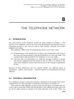
PERSONAL WIRELESS
COMMUNICATION SYSTEMS
11.1 INTRODUCTION
The idea that a person could carry around with him a telephone booth of his own is a
very attractive one. However, the technology required to make the telephone booth
small and light enough for this to be possible, and furthermore convenient to carry,
has been available only in the last 30 years. Mobile radio has been available in North
America since the 1930s but they were exclusive in the hands of the police. Later
taxicab operators installed radios in their vehicles. These mobile units were large,
heavy and electrical power hungry. They used amplitude modulation which is
notorious for poor performance in the presence of electrical noise and there was
more than enough noise generated by the ignition systems of the vehicles in which
they were installed. Moreover, they were operational in either the transmit or the
receive mode at any given time; they were of the ‘‘push-to-talk’’ type.
The invention of the transistor and its progression to integrated circuits made it
possible to reduce the weight and size of circuits and, at the same time, increase their
capability and flexibility. These advances were accompanied by an enormous
reduction in the amount of power required to operate transistor circuits. The stage
was set for the introduction of the ‘‘personal telephone booth’’.
There are many applications in which radio plays a vital part. These go from
‘‘remote keys’’ for the automobile, garage door openers, pagers, walkie-talkies,
cordless telephones to cellular telephones with access to the Internet. In this chapter,
we limit ourselves to a discussion of paging systems, cordless and cellular
telephones. The paging system was designed to send information from a base
station to a mobile terminal. The mobile terminal has no capability to transmit
information in the opposite direction. A serviceman for home heating furnaces, for
example, only needs to know the address of his next assignment; in general, he does
not have to contact his base office. A communication system in which information
travels in only one direction is described as simplex and the pager is an example.
325
Telecommunication Circuit Design, Second Edition. Patrick D. van der Puije
Copyright # 2002 John Wiley & Sons, Inc.
ISBNs: 0-471-41542-1 (Hardback); 0-471-22153-8 (Electronic)
Radio systems with a push-to-talk button use the same channel in both the forward
and reverse directions. It is therefore necessary for each person to indicate when they
have finished talking with the familiar word ‘‘ roger’’. They are described as half-
duplex.Afull-duplex system uses two channels simultaneously, the first for
transmission and the second for reception. The cellular telephone is an example
of a full-duplex system.
11.2 MODULATION AND DEMODULATION REVISITED
In Section 9.2.1 we discussed the generation of a single-sideband-suppressed carrier
(SSB-SC) signal using a balanced modulator and a bandpass filter. Fig. 11.1(a)
shows the circuit configuration of the SSB-SC as well as the frequency spectrum of
the input and output. The output shows that the baseband signal has experienced an
upward frequency shift equal to the carrier frequency, o
c
and an ‘‘inverted’’ version
of it appears at a lower frequency and the two are symmetrically spaced about the
position of the carrier. A bandpass filter is used to select the upper sideband. Clearly,
the upper and lower sidebands contain the same information and only one of them
should be required for the recovery of the original signal.
Figure 11.1(b) shows a circuit in which upper sideband is multiplied (balance
modulated) with the carrier signal, o
c
. The corresponding spectrum shows that the
Figure 11.1. (a) The structure of the modulator and the spectrum of the corresponding
frequency shift. (b) The structure of the demodulator and the spectrum of the corresponding
frequency shift.
326 PERSONAL WIRELESS COMMUNICATION SYSTEMS
output has two ‘‘sidebands’’. The first is at a frequency 2o
c
and the second occupies
the position of the original baseband signal in the spectrum. The original signal is
recovered by using a lowpass filter. Equations (9.2.1 to 9.2.5) are the relevant
equations.
This modulation and demodulation technique can be used with amplitude,
frequency and phase or angle modulation schemes. When demodulation is carried
out using the carrier signal in a balanced modulator as shown in Figure 11.1(b), it is
referred to as coherent demodulation or coherent detection. The use of an envelope
detector to demodulate an AM signal is known as non-coherent demodulation.
11.3 ACCESS TECHNIQUES
11.3.1 Multiplex and Demultiplex Revisited
When modulation is used to accommodate a number of signals on a single channel
we refer to it as multiplexing. Figure 11.2 shows five baseband signals, each of
which occupies the frequency band 300 Hz to 3 kHz.
By choosing suitable carrier frequencies for each one, they may be transmitted
over the same cable or the airwaves by radio and subsequently demodulated with no
interference between them. When different carrier frequencies are used to multiplex
the baseband signals, it is referred to as frequency-division multiplex (FDM). Other
methods of multiplexing are described below.
The success of personal wireless communication systems is in part due to the
development of techniques which allowed a large number of signals to share a
limited spectrum. One of the boundaries of the spectrum available for personal
wireless communication is dictated by the size of the antenna for the radio interface.
Efficient transmission of radio signal at low frequency requires antennas several
thousand meters tall. Clearly, this is not possible as portability of the device is
essential. The boundary on the other end of the spectrum is set by the character of
high-frequency transmission which increasingly takes on the properties of visible
light which requires line-of-sight. Clearly, the modern environment (cities) in which
most of the potential subscribers live and work make line-of-sight communication
Figure 11.2. Five baseband signals occupying the same bandwidth can be separated by using
frequency-division multiplex.
11.3 ACCESS TECHNIQUES 327
devices inadmissible. Between these two boundaries we have other systems in
competition for the spectrum, such as air and sea navigation, satellite communica-
tion, radio and television broadcasting.
It so happens that national governments have arrogated to themselves the power
to assign portions of the spectrum for specific purposes within their territories and to
negotiate international treaties which govern their use. This, in short, brings us to the
assigned frequency bands of 824–849 MHz and 869–894 MHz for personal wireless
communication. For the large number of anticipated subscribers to be accommo-
dated in such a restricted bandwidth it is necessary to develop techniques which
reduce the possibility of interference with each other.
One major factor working in our favor is that, provided we keep the radiated
power below a given level, and we are separated sufficiently by distance, we can
reuse the spectrum over and over again. We shall now discuss the techniques which
enable us to share the spectrum available.
11.3.2 Frequency-Division Multiple Access (FDMA)
Frequency-division multiple access is a fancy name for what is commonly done with
AM and FM radio broadcasting and TV stations; they are assigned different carrier
frequencies with suitable separation between them to ensure minimal interference
with each other. They are required by law to keep their carrier frequencies constant.
They also have a limited bandwidth and radiated power. The division of the spectrum
according to frequency was discussed in Section 9.2 under the heading ‘‘Frequency-
Division Multiplex’’ (FDM). Figure 11.3 shows a representation of the channels
spaced by their assigned carrier frequencies and separated by limited bandwidth and
appropriate guard bands.
11.3.3 Time-Division Multiple Access (TDMA)
In FDMA, a frequency band is dedicated to a particular channel for as long as it is
required. In TDMA, several channels share the same bandwidth but each channel
has the use of that bandwidth for a fraction of the time. TDMA was discussed in
Section 9.3 under the other name used to describe this technique: ‘‘Time-Division
Figure 11.3. In frequency-division multiple access (FDMA), channels are spaced by their
assigned carrier frequencies and separated by limitation on bandwidth and appropriate guard
bands.
328 PERSONAL WIRELESS COMMUNICATION SYSTEMS
Multiplex’’ (TDM). The basis of this technique is the ability to reconstruct a signal
from samples taken from it. Figure 11.4 shows how each channel is structured in
time to form frames and the sequences of the content of each channel. In TDMA, it
is necessary to synchronize the transmitter to the receiver so that bits from one
channel do not end up in another channel, hence the synchronizing bits.
11.3.4 Spread Spectrum Techniques
In spread spectrum communication systems the radio-frequency carrier is changed
very rapidly in a pseudo-random fashion over a bandwidth which is much wider than
the minimum required to transmit the signal. Potentially it should cause interference
with other users of the airwaves but, in fact, because the carrier operates for such a
short time at any given frequency, its effect is almost imperceptible. The average
perceived power on any given channel is very low and it therefore behaves like a
low-power noise source spread across the bandwidth it uses. Many communication
channels can operate in this fashion without interfering with each other. Spread
spectrum technology has been of particular interest to the military because it is
almost impossible to predict the next frequency of the transmission; they like to stay
away from eavesdroppers and to avoid the jamming of their communication systems
by the enemy. The real challenge in spread spectrum communication is to keep the
receiver synchronized to the transmitter. We shall return to the problem of
synchronization later.
There are two major types of spread spectrum techniques. They are frequency
hopped and direct sequence spread spectrum technologies.
11.3.4.1 Frequency Hopped Multiple Access (FHMA). In FHMA trans-
mission, the information is first digitized and then broken up into short passages.
Each passage is transmitted on a different carrier frequency determined by a pseudo-
random number generator. Because the modulation used is either narrow band FM or
frequency-shift keying, at any instant, a frequency hopped signal occupies a single
narrow channel. However, because the carrier frequency hops around, it makes use
of a much wider bandwidth. Figure 11.5 shows a representation of a system that uses
FHMA. Clearly, in an FHMA the receiver has to have prior access to the sequence of
the carrier frequencies transmitted as well as the timing to be able to follow the hops
(synchronize). It is quite likely that two or more transmitters will at some time try to
use the same frequency.
11.3.4.2 Code Division Multiple Access (CDMA). In CDMA transmission,
the information is first digitized and then multiplied by a binary pseudo-random
sequence of bits (called chips) with a bit rate much higher than that of the digitized
information [1]. Figure 11.6 shows the binary message signal, bits of a pseudo-
random code, and the spread spectrum (coded) signal.
Note that, because the bit rate of the pseudo-random sequence is much higher
than that of the message signal, it requires a much larger bandwidth for its
transmission. The spread signal is used to modulate a carrier (usually FM or PM)
11.3 ACCESS TECHNIQUES 329
Figure 11.4. In time-division multiple access (TDMA), each channel is structured in time to form
frames and the sequence of the content of each channel.
330
and then transmitted. At the receiving end the spread signal is demodulated then
decoded using a locally generated pseudo-random bit sequence in a process called
correlation. Because the number of chips representing a message bit (1 or 0) is large,
the correlation does not have to be perfect; it has to correctly recognize the majority
of the chips as representing that message bit (1 or 0). In a system which is subject to
multipath fading, this is an advantage. It is clear that the receiver has to have prior
knowledge of the pseudo-random code to be able to decode the message. To other
receivers not using the identical code, the message appears to be just noise. The
attraction of this technique is that it can be used to accommodate a large number of
subscribers with different codes and they will not even know that they are sharing
the same bandwidth. A by-product of CDMA is improved security of the message.
One disadvantage of CDMA is that the power of individual transmitters has to be
controlled very carefully. A strong signal from one of the transmitters within the
wideband can overwhelm the sensitive front-end of the system and prevent the
reception of other signals. The transmit power control system for all the mobiles
adds complexity and costs.
11.4 DIGITAL CARRIER SYSTEMS
So far, we have discussed carrier systems in which the message signal is in analog
form. Increasingly, electronic systems are using a digital format. For example, it has
Figure 11.5. A representation of a frequency hopped multiple access (FHMA) system.
Although no instances of two or more transmission on the same frequency and at the same
time are shown, there is a clear possibility that this can happen. Note that for simplicity, all
channels have equal bandwidth and occupy that bandwidth for the same length of time. Neither
of these conditions apply in practice.
11.4 DIGITAL CARRIER SYSTEMS 331
Figure 11.6. The binary data and its equivalent bipolar form, the pseudo-random sequence (chips)
and the resulting spread spectrum data.
332
taken the music recording industry less than 15 years to replace the analog vinyl
record with the digital compact disc. There are technical as well as economical
advantages to be gained from this move. Moreover, the advent of integrated circuit
technology with its ability to fabricate extremely large numbers of circuits on
minuscule pieces of semiconductor has made the move to digital systems seem
inevitable.
To transmit a baseband (message) signal over a radio channel, it is necessary to
change some property of the radio-frequency signal using the baseband signal. We
can change its amplitude, its frequency, or its phase angle. In Chapter 2 we discussed
the modulation of a radio-frequency signal by a message signal in which the
amplitude of the RF signal varied according to the amplitude of the message signal
(amplitude modulation; AM). In Chapter 4 we discussed how to change the
frequency of the RF about a fixed value using the message signal (frequency
modulation; FM). It is now time to discuss the modulation scheme in which we vary
the phase of the RF signal according to the message signal (phase modulation; PM).
It must be pointed out that frequency and phase modulation are, in fact, the same.
The only difference is that in PM the phase of the modulated waveform is
proportional to the amplitude of the modulating waveform, while in FM it is
proportional to the integral. Both schemes are sometimes referred to as angle
modulation. Phase modulation, when the message signal is a continuous (analog or
tone) function, does not appear to have any practical applications. When the message
signal is digital, it has distinct advantages such as improved immunity to noise.
11.4.1 Binary Phase Shift Keying (BPSK)
When the modulating (message) signal is in binary form we refer to it as keying.
This is a left-over from the days when telegraph operators opened and closed a
circuit (presumably, using a ‘‘Morse key’’ ) to generate Morse code.
Figure 11.7 shows a comparison of the waveforms of the three modulating
schemes.
It should be noted that, for clarity, the RF has been chosen to be only four times
the data rate. In practice, the RF is much higher than the data rate.
If we represent the digit 1 by the binary pulse pðtÞ¼1, the digit 0 by pðtÞ¼À1
and the carrier by cos o
c
t, then after modulation we have
sðtÞ¼pðtÞ cos o
c
t ð11:1Þ
for the digit 1 and
sðtÞ¼ÀpðtÞ cos o
c
t ¼ pðtÞ cosðo
c
t þ pÞð11:2Þ
for the digit 0.
Demodulation of a BPSK signal requires a balanced mixer and an exact replica of
the carrier.
11.4 DIGITAL CARRIER SYSTEMS 333
11.4.2 Quadrature Phase Shift Keying (QPSK)
In quadrature phase shift keying, the message signal is separated into in-phase (I)
and quadrature-phase (Q) components and are then modulated separately by two
carriers of the same frequency but with a phase difference of 90
. QPSK is used
because twice the information can be carried in the same bandwidth as when BPSK
is applied [2].
Figure 11.8 shows the structure of the QPSK modulator. It has been assumed that
the pulses used for modulating the carrier are rectangular. In fact, rectangular pulses
are quite undesirable since, in a limited bandwidth channel, they tend to smear into
the time intervals of other pulses [3]. The pulse shaping filter is used at the baseband
or at the IF stage to limit adjacent channel interference.
Figure 11.9 shows the waveforms of the original data, the I and Q components,
the I cos ot and Q sin ot as well as the QPSK signal. Note that the QPSK signal is a
combination of the waveforms of the I cos ot and Q sin ot components.
The demodulation of the QPSK signal is done coherently as shown in Figure
11.10. After down-conversion the received signal is split into two parts and each part
is demodulated using a carrier signal derived from the received signal by a carrier
Figure 11.7. (a) Binary data, (b) its bipolar equivalent, (c) the amplitude-modulated waveform,
(d) the frequency-modulated waveform, and (e) the phase-modulated waveform.
334 PERSONAL WIRELESS COMMUNICATION SYSTEMS
Figure 11.8. Block diagram of the QPSK modulator.
335
Figure 11.9. The waveforms of (a) the data, (b) the non-return-to-zero in-phase (I) component,
(c) the non-return-to-zero quadrature (Q) component (note that the waveform shown in (a) is not
coincident in time with those shown in (b) and (c)),(d) I cos ot,(e) Q sin ot,(f ) the QPSK signal,
and (g) the QPSK signal with the phase shifted by þp=4.
336 PERSONAL WIRELESS COMMUNICATION SYSTEMS
Figure 11.10. Block diagram of the QPSK demodulator.
337
recovery circuit. The low-pass filters remove the undesirable products of the
multiplication process. Two circuits make decisions on whether the bit that was
sent was a 1 or a 0. The I and Q components are passed to a multiplexer which
reconstitutes the original binary signal.
11.5 THE PAGING SYSTEM
There are a number of occupations in which the professional has to move around
from one job to the next and essentially is almost never available at a wireline
telephone. The paging system is designed to receive and store information until the
professional is ready to read it. They are most commonly used by home appliance
servicemen, office equipment servicemen, doctors, photographers, and in the last
few years they have become very popular with teenagers. Different paging systems
have varying capabilities. The message received and stored may be as simple as
‘‘Call the paging center to pick up your message’’ or it may give the number of the
caller or an alphanumeric message, or in some of the more sophisticated systems the
caller can leave a voice message. The important difference between paging and other
systems of communication is that in paging, there is no need for an immediate
response.
11.5.1 The POCSAG Paging System
In this section, we discuss the design and operation of one of the simpler paging
systems currently in use. This is the Post Office Code Standardization Advisory
Group (POCSAG) system. This system was introduced in the early 1980s as a
standard for the manufacture of pagers for the British Post Office. It can handle up to
2 million addresses per carrier and supports tone only (alert only), numeric, and
alphanumeric pagers. There are three speeds at which the POCSAG system transmits
its messages; they are 512, 1200, and 2400 bps. These data rates would normally be
considered to be slow but this is deliberate because, combined with high transmitter
power (hundreds of watts to a few kilowatts), it improves reliability. The message is
‘‘broadcast’’ over the entire area of operation and it is supposed to reach the
recipients whether they are in a building, on a highway, or in an airplane. Typical
carrier frequency of operation of the transmitters is around 150 MHz. Each message
is preceded by a CAP code which is a unique 7 or 8 digit code recognizable to only
one paging receiver in the geographic area of operation.
11.5.1.1 The Paging Transmitter. Figure 11.11 shows a block diagram of the
transmit portion of the paging system. Most of the messages come in over the
telephone system. The source of the message can be from a Touch-tone
1
telephone
whose keypad can be used to enter the information to be transmitted. It can be a
voice message, in which case a human dispatcher in the paging center has to
intervene and key in the appropriate message. The message can also come from a
computer with the appropriate software and a modem. Whatever its source or form,
338 PERSONAL WIRELESS COMMUNICATION SYSTEMS
the message goes into an A=D converter. The digital output is used to drive a
frequency shift keying encoder in which the digit 0 is assigned a frequency of, say,
1200 Hz and the digit 1 is represented by a tone of frequency 2400 Hz. The message
is placed in a queue with other messages. The appropriate CAP code is inserted
ahead of each message frame. The dual tone signals may be sent over landlines or
wireless systems to a large number of frequency modulated transmitters distributed
over a geographic area.
11.5.1.2 Component Circuit Design. The function of the ‘‘ processor’’ is to
condition the analog signals coming over the telephone line into the paging center
for the A=D converter. The human dispatcher plays the same role. The design of the
A=D converter is described in Section 8.5.1.2. The frequency shift keying encoder is
a form of modem. Modem circuits are described in Section 9.4.1. The frequency
modulated (FM) radio transmitter was the subject of Chapter 4.
11.5.1.3 The Paging Receiver. The block diagram of the basic paging
receiver is shown in Figure 11.12 [4]. The paging receiver is typically a small
device which can be worn on a waist belt. It is basically an FM receiver with a fixed
carrier frequency. It has an internal antenna typical of portable radios. Each receiver
has a unique CAP code programmed into it and when a message arrives with the
appropriate CAP code, the message is saved in the memory and the controller
triggers the alert generator which sends a signal to the alert transducer. All other
messages are ignored. The alert may be in the form of a sub-audio vibration, a
Figure 11.11. Block diagram of the transmit portion of the paging system.
11.5 THE PAGING SYSTEM 339
chime, a beep, or a short excerpt of a well known tune. For a ‘‘ tone only’’ paging
receiver, the wearer is simply alerted and has to place a call to a messaging center to
get the message. For numeric and alphanumeric receivers, the stored message can be
retrieved by pushing the appropriate buttons on the front of the device. On receiving
the appropriate commands from the keypad, the controller causes the output data
control to send the stored information to the decoder which converts it into a form
suitable for display on the liquid crystal display (LCD). The messages remain in the
memory until they are cleared.
11.5.1.4 Component Circuit Design. The frequency modulated radio recei-
ver was the subject of Chapter 5. A frequency shift keying decoder was discussed in
Section 9.4.1 (modems). Memory circuits, their control, coding, and decoding are
discussed in Appendix E.
11.5.1.5 Liquid Crystal Display. Certain chemical compounds, such as the
cyanobiphenols, have the property that causes the rotation of polarized light passing
through them. These compounds are normally transparent to visible light but when
seen in a container they appear to be translucent. This is because the axes of the
molecules are normally randomly oriented and hence they scatter light in random
directions. When an electric field is applied to the compound, the axes of the
molecules line up and, depending on the orientation of the incident polarized light,
they allow the light to go through or stop it [5]. It is possible in some of the most
commonly used liquid crystals to make the light ‘‘ twist’’ or gradually change its
orientation as it travels through the liquid. This phenomenon is known as twisted
nematic and the degree of twist can be set during manufacture. This is the basis of
the common liquid crystal display which is used in watches, pagers, and many other
electronic consumer goods.
Figure 11.12. Block diagram of the paging receiver.
340 PERSONAL WIRELESS COMMUNICATION SYSTEMS
Figure 11.13 shows two parallel transparent electrodes with backings of polariz-
ing film, one vertically oriented and the other horizontally oriented. The space
between the electrodes is filled with the liquid crystal compound.
When the light enters the vertically polarized film, only the vertical component
will pass through and enter the liquid crystal. As it travels from the right-hand
electrode to the left-hand electrode its orientation is changed from the vertical to the
horizontal. If the left-hand side polarizing film is oriented horizontally, the light will
pass through it.
When an electric field is applied across the electrodes the axes of the molecules
are lined up such that they do not affect the orientation of the light. The vertically
polarized light cannot go through the horizontally polarized left-hand side film. The
contrast created by the presence or absence of the electric field is exploited in the
application of the liquid crystal as a display transducer.
In the display of alphanumeric characters, the most commonly used units are the
seven-segment and the dot-matrix displays [6]. The dot-matrix display is the more
versatile of the two but its decoding system is more complex. The decoding of
information in a binary format for display by the relatively simple seven-segment
display is not as simple as might be expected and an explanation of how it is
designed will be an unnecessary diversion at this point. The seven-segment
LCD and its driver, the MC5400=7400 series integrated circuit, are presented in
Appendix F.
11.5.2 Other Paging Systems
Since the early 1980s when the POCSAG system was introduced, a number of new
systems have been developed. They have increased the speed of transmission,
lowered the current drain on the battery, increased the number of addresses per
carrier, improved reliability, and made the system more difficult to tamper with. Two
of these systems are described very briefly below.
(1) ERMES (European Radio Message System). This system was introduced
in the early 1990s by the European Community. The data rate is fixed at
6250 bps and it is capable of operating over multiple radio-frequency
channels. The pager can scan all the channels when the subscriber is away
from his home base.
(2) FLEX
TM
(Flexible wide-area paging protocol). This system was intro-
duced in 1993 as a high performance multi-speed paging protocol (1600,
3200 and 6400 bps). FLEX can support over 5 Â 10
9
addresses and
conserves the pager battery life by sending data in specified time slots only
[7].
At the end of the 20th century it was estimated that there were 192 million pages
in use world-wide [8].
11.5 THE PAGING SYSTEM 341
Figure 11.13. An illustration of the operation of the liquid crystal as a display transducer. Reprinted
with permission from W. C. O’Mara, Liquid Crystal Flat Panel Display, Van Nostrand Reinhold, New
York, 1993.
342
11.6 THE ANALOG CORDLESS TELEPHONE
The cordless telephone was designed to liberate the telephone user from the tether
that the handset cord is. Before cordless telephones appeared on the market, long
handset cords were used to increase the distance between the handset and the base
but the longer the cord got the more clumsy it became. The cordless telephone not
only increased the distance from the base, it made the handset completely portable.
11.6.1 System Design
Figure 11.14 shows the configuration of the cordless telephone. The base station is
connected directly to the Public Switched Telephone Network (PSTN) and, from the
point of view of the PSTN, it is just another telephone set. In fact, part of it is a
transceiver which provides a two-way link to the handset. It can transmit signals to
the handset and receive signals from the handset for onward transmission to the
PSTN. The telephone part of the system is the same as any wireline telephone set
(see Chapter 8) and the radio part of it uses frequency modulation (see Chapters 4
and 5) in the 900 MHz band. The base station transmitter operates at one frequency
(say, 925.997 MHz) while the handset transmitter operates at another frequency (say,
902.052 MHz). This is an example of two simplex systems which form a frequency-
division duplex (FDD). A device called a duplexer provides a coupling between the
antenna and both the transmitter and the receiver. Other frequencies were used in the
past and a new generation of cordless telephones, using digital technology, have
been assigned spectra in the 2.4 GHz band in North America.
The handset antenna is coupled to both the FM transmitter and receiver by the
duplexer. Separate amplifiers condition the signal from the microphone and the
signal going to the speaker appropriately.
11.6.2 Component Design
The designs of all the components in Figure 11.14 were discussed earlier with the
exception of the duplexer.
11.6.2.1 The Radio-Frequency Duplexer. The role of the RF duplexer is to
couple the strong signal from the transmitter to the antenna with minimal loss but
prevent the transmitter signal from reaching the input of the receiver. In many
applications, such as radar and the wired telephone system, a hybrid performs this
function (see Sections 8.3.6.1 and 8.4.3). The duplexers in both the base station and
the handset have to ensure that the path from their transmitter to their receiver has
the highest possible attenuation so that no significant local feedback is possible. At
the same time they must ensure that the path from the transmitter to the antenna and
that from the antenna to the receiver have minimum attenuation. There are two
important factors to consider. The fact that the transmit and receive frequencies are
separated by a fairly wide margin of approximately 25 MHz is a great help in the
design. The fact that the signal power from the transmitter of the handset to its
11.6 THE ANALOG CORDLESS TELEPHONE 343
Figure 11.14. Block diagram of the cordless telephone: (a) the base station, (b) the handset.
344
antenna is several orders of magnitude greater than the signal power reaching the
handset antenna from the base station makes the design of the duplex filters critical.
The same is true for the base station duplexer.
The connection of the antenna to the duplex filters is shown in Figure 11.15(a).
The attenuation characteristics of typical transmit and receive filters are shown in
Figure 11.15(b). Note that at the center of the transmit filter passband (BPF(a);
forward) there is a loss of about 2.5 dB but at this frequency the receive filter
(BPF(b); reverse) has an attenuation in excess of 50 dB [9]. This means that the path
of the transmitter signal to the antenna (double-headed arrow) has minimal loss
while the path of the transmitter signal to the input of the receiver has very high
attenuation. This is the critical path because, if the transmitter signal was allowed to
leaking into the input of the receiver, there would be a possibility of instability in the
system. It is also critical that the weak signal from the antenna reaches the input of
the receiver with minimal attenuation (single-headed arrow). Leakage of this signal
into the output of the transmitter is not critical.
Figure 11.15. (a) A block diagram of the transmit and receive surface acoustic wave (SAW)
filters, (b) the frequency characteristics of the two filters.
11.6 THE ANALOG CORDLESS TELEPHONE 345
There are three types of RF duplexer technologies used in cordless telephones.
They are ceramic, Surface Acoustic Wave (SAW), and Film Bulk Acoustic
Resonator (FBAR). Ceramic RF duplexers are considered to have superior operating
characteristics compared to SAW devices but they are, in general, bulkier. FBAR is a
new technology that is supposed to match the performance while occupying only
about 10% of the space of ceramic devices.
11.6.2.2 Surface Acoustic Wave Radio Frequency Duplex Filter. The
design of filters is outside the scope of this book; however, the basics of a surface
acoustic wave (SAW) device are easy to appreciate. A typical SAW device is shown
in Figure 11.16. It consists of a piezoelectric substrate such as quartz, lithium
niobate (LiNbO
3
), lithium tantalate (LiTaO
3
) and lithium borate (Li
2
B
4
O
7
). These
crystalline materials are cut at specific angles relative to the crystal axes and highly
polished. Thin-film inter-digital electrodes are deposited on the surface as shown in
Figure 11.16. Piezoelectric materials have the property of undergoing a mechanical
deformation when an electric field is applied to them. Equally, they produce an
electric field when they are deformed mechanically. When an alternating voltage is
applied to the input electrode, it causes a mechanical deformation on the surface of
the crystal which propagates in both directions, left and right. Part of the wave
travelling to the left will be reflected at the end of the substrate and there will be
losses associated with it. The wave travelling to the right will reach the output
electrode where the mechanical wave will induce a voltage in the receive electrode.
The amount of coupling between the two electrodes depends on a large number of
factors such as the frequency of the signal, the crystal material, the angle of the cut
of the crystal relative to its axes, and the geometry of the inter-digital transducers.
The most widely used SAW devices in cordless and cellular telephones are not
considered to operate in a truly surface acoustic wave mode. They are generally
described as leaky surface acoustic wave (LSAW) devices. This nomenclature is
Figure 11.16. A typical surface acoustic wave (SAW) filter showing the input and output
transducers. Reprinted with permission from C. K. Campbell, Surface Acoustic Wave Devices for
Mobile and Wireless Communication, Academic Press, San Diego, CA, 1998.
346 PERSONAL WIRELESS COMMUNICATION SYSTEMS
appropriate because the mechanical deformation that takes place in LSAW devices
does not limit itself to the surface of the crystal; it penetrates the material.
11.6.3 Disadvantages of the Analog Cordless Telephone
The range of the cordless telephone is limited to less than 200 m because its radiated
RF power is limited to less than 0.75 mW. The distance limitation is not necessarily a
disadvantage since the frequencies on which it operates can be reused by other
cordless telephone users outside the 200 meter radius with minimal or no inter-
ference. The real disadvantage of the system is that, because it uses a radio link with
no attempts at encryption, anyone with an FM radio capable of operating in the
frequency bands assigned to cordless telephones can tune in and listen to the
conversation. As mentioned earlier a new frequency band at 2.4 GHz has been
assigned to cordless telephones in North America. These cordless telephones are
digital, have a longer range (400 m), and use Spread Spectrum technology to ensure
that private conversations remain private.
11.7 THE CELLULAR TELEPHONE
The cellular telephone system can be considered to be an ‘‘enlarged’’ form of the
cordless telephone. A number of steps have to be taken to make such an expansion
feasible.
(1) To increase the range of the mobile or portable the number of base stations
will have to be increased from one to many. This also establishes a need for
the mobile=portable to be switched from one base station to the next
seamlessly when it is on the move. This process is called handoff.
(2) To make the system economically feasible, it will have to handle a large
number of telephone conversations simultaneously. This means that the
number of channels in the base station must be increased from one to
many and interference between the channels must be avoided.
(3) Due to the variability of the path between the base station and the mobile,
fragments of the signal will find their way to the receiving antenna over
different paths, resulting in different amplitudes and phases. The vector sum
of the fragments may result in an augmentation or, with equal probability, a
total cancellation of the signal. This process is called fading. It is necessary to
take steps to keep the signal strength within acceptable limits.
A cellular telephone system which has the above attributes is the Advanced Mobile
Phone System (AMPS).
11.7 THE CELLULAR TELEPHONE 347
11.7.1 System Overview
Figure 11.17 shows the configuration of the cellular telephone system. The
hexagonal cell from which the system derives its name happens to be a convenient
way to divide a geographic area without overlap. The radiation pattern of the antenna
at the center of the cell is, in theory, a circle but using circles on a map will produce
overlaps and=or voids. The effects of geographical features such as hills, buildings
and other structures make the radiation pattern of the antenna difficult to predict. At
the center of each cell there is a base station which is connected to the Mobile
Telephone Switching Office (MTSO). The MTSO is connected to the PSTN.
The MSTO is the nerve center of the cellular system. It controls every parameter
of the conversation from when a subscriber requests service to when she terminates
the call.
11.7.2 Advanced Mobile Phone System (AMPS)
It has been estimated that at the end of 1997 there were 50 million cellular
telephones in the United States [3]. In Canada the number was 7.5 million. With
a growth rate of over 50% a year, the estimate for the year 2000 is close to 200
million cellular telephones in use in North America. Although there has been a shift
towards digital cellular technology, the majority of cellular telephones in use in
North America are based on AMPS. The AMPS cellular system, like the cordless
telephone, uses FM radio as part of the interface between the subscribers and the
PSTN. The AMPS uses frequency-division multiple access (FDMA). FDMA, when
applied to AMPS, means that each mobile telephone is assigned two carrier
frequencies for voice; one for communication from the base station to the mobile
(forward or downlink) and the other from the mobile to the base station (reverse or
uplink). In addition there are channels set aside for establishing calls and for
monitoring and control of the system. These are called traffic or control channels
and are shared by many mobiles.
AMPS uses two bands of frequencies: the forward channels from 869 to 894 MHz
and the reverse channels from 824 to 849 MHz. The following are part of the system
specification:
Figure 11.17. The configuration of the cellular telephone system.
348 PERSONAL WIRELESS COMMUNICATION SYSTEMS
(a) There are two simplex channels combined to form a duplex.
(b) For each mobile, the forward carrier frequency is 45 MHz higher than the
reverse.
(c) Each channel occupies a bandwidth of 30 kHz.
(d) The total number of channels is 832.
11.7.2.1 Reuse of the Channels. Figure 11.18 shows the cells clustered in
groups of seven [3]. With such an arrangement, it is possible to reuse the carrier
frequencies in all cells marked (a), (b), (c) and so on, so long as the radiated power
of each mobile in the cell is kept below the appropriate level considering the distance
between the respective cells (a), (b), (c), etc. The minimum frequency reuse distance
can vary quite widely. In densely populated centers, the cells are made smaller and
there are more of them. The radiated power levels are much lower. In more sparsely
populated areas, the cells are larger and the radiated power is higher.
11.7.2.2. Setting up the Call. The steps described below have been simplified
considerably in the interest of brevity and clarity.
When a cellular telephone is turned off, the system has no way to reach the
subscriber. If the telephone is on but not yet engaged in a conversation (idle), the
Figure 11.18. The formation of seven-cell clusters which permit frequency reuse under
specified radiated power and minimum distance of separation.
11.7 THE CELLULAR TELEPHONE 349