Lifetime-Oriented Structural Design Concepts- P12 potx
Bạn đang xem bản rút gọn của tài liệu. Xem và tải ngay bản đầy đủ của tài liệu tại đây (745.09 KB, 30 trang )
288 3 Deterioration of Materials and Structures
the drained thermo-mechanical coupling tensor
A = A
u
− 3α
t,u
MB = C
C
C
ed
: 1α
t
, (3.149)
and the drained tensor
Λ = Λ
u
+ ΞB, (3.150)
respectively [321].
3.3.2.1.3 Identification of Coupling Coefficients
According to [321] the poroelastic hygro-mechanical coefficients b and M can
be determined by relating differential stress and differential strain quantities
defined on the meso-level to respective homogenised quantities on the macro-
level. The so-obtained tangential Biot coefficient is determined as
b = S
l
1 −ψ
K
K
s
, (3.151)
which includes the expression b = S
l
suggested by [211] for the special case
of poroelastic materials with incompressible matrix behaviour. An expression
for the Biot modulus
M = ψM is obtained as
M =
φ
1 −
S
l
p
l
K
s
∂S
l
∂p
l
+
φS
l
K
l
+
S
l
(b −φS
l
)
K
s
−1
(3.152)
see [705, 493] for a similar formulation. For cementitious materials, expression
(3.152) can be replaced by
M ≈
φ
∂S
l
∂p
l
−1
. (3.153)
In the special case of a fully saturated material (S
l
= 1), (3.152) yields the
classical relation [211, 493]
M
S
l
=1
=
φ
K
l
+
(b − φ)
K
s
−1
. (3.154)
The coefficients related to damage phenomena Λ and Ξ are identified by
exploiting the symmetry relations that are connected to the existence of a
macroscopic potential. Using the Maxwell symmetries, the drained tensor
Λ can be expressed as [533]
Λ = C
C
C :(ε −ε
p
− ε
f
)+
K
K
s
p
l
S
l
dp
l
1 −C
C
C : 1α
t
T,
(3.155)
and the coupling coefficient Ξ is obtained as
Ξ =
MS
l
K
K
2
s
p
l
S
l
dp
l
≈ 0. (3.156)
3.3 Modelling 289
3.3.2.1.4 Effective Stresses
The concept of effective stress [281, 791] is a generally accepted approach in
soil mechanics for the determination of stresses in the skeleton of fully satu-
rated soils. In addition to the original proposal of [791], several alternative sug-
gestions for the definition of effective stresses exist, taking the compressibility
of the matrix material or the porosity into account (see e.g. [123, 587, 128]).
Based on the relevance of the concept of effective stress for the analysis of
fully saturated soils, this concept has also been adapted for the description of
partially saturated soils. Early formulations introduced the capillary pressure
in the (elastic) effective stress definition [127]. However, difficulties to obtain
satisfactory agreements with experimental results have motivated the use of
two independent stress fields for the constitutive modelling of unsaturated
soils (see e.g. [129, 44]).
As far as the numerical modelling of partially saturated cement-based mate-
rials is concerned, the assumption of (elastic) effective stresses seems not to be
well suited for the description of shrinkage-induced cracks using stress-based
crack-models. However, the concept of plastic effective stress first introduced
at a macroscopic level by [210] for saturated porous media (see [211] for de-
tails), allows to overcome these difficulties in the framework of poroplasticity
– porodamage models. The proposed form of the plastic effective stress is the
same as the classical Biot-type, however, a plastic effective stress coefficient
is used. A similar form has been derived from micromechanical considera-
tions by [510]. This concept has been recently extended to partially saturated
materials [167, 533], and is also adopted in the present formulation. From
the coupled relations between total stresses, strains, liquid saturation and
temperature
σ = ψC
C
C :(ε −ε
p
− ε
f
)
+
1 −ψ
K
K
s
p
c
S
l
(p
c
)dp
c
1 −AT,
(3.157)
the following definition of the elastic effective stress tensor
σ
e
= ψC
C
C :(ε −ε
p
− ε
f
) − AT, (3.158)
with
σ = σ
e
+
1 −ψ
K
K
s
p
c
S
l
(p
c
)dp
c
1. (3.159)
is obtained. The plastic effective stress tensor σ
p
= σ
, defined as
σ
= σ − b
p
p
c
1, (3.160)
290 3 Deterioration of Materials and Structures
characterises the thermodynamic force associated with the plastic strain rate
[211]. In contrast to the elastic effective stress tensor, σ
represents the macro-
scopic counterpart to matrix-related micro-stresses with the coefficient b
p
as
the plastic counterpart of the Biot coefficient b. By relating stress quantities
on the meso-scale to respective macroscopic quantities, a possible identifi-
cation of b
p
as a function of the integrity ψ,theporosityφ and the liquid
saturation S
l
can be accomplished as
b
p
= ψφS
l
(p
c
) , (3.161)
see [321] for details.
3.3.2.1.5 Multisurface Damage-Plasticity Model for Partially Saturated
Concrete
According to the concept of multisurface damage-plasticity theory, mecha-
nisms characterised by the degradation of stiffness and inelastic deformations
are controlled by four threshold functions defining a region of admissible stress
states in the space of plastic effective stresses σ
E = {(σ
,q
k
)| f
k
(σ
,q
k
(α
k
)) ≤ 0,k=1, , 4}. (3.162)
In (3.162), the index k =1, 2, 3 stands for an active cracking mechanism asso-
ciated with the damage function f
R,k
(σ
,q
R
)andk = 4 represents an active
hardening/softening mechanism in compression associated with the loading
function f
DP
(σ
,q
DP
).
Cracking of concrete is accounted for by means of the Rankine criterion,
employing three failure surfaces perpendicular to the axes of principal stresses
f
R,A
(σ
,q
R
)=
A
− q
R
(α
R
) ≤ 0,A=1, 2, 3. (3.163)
In (3.163), the subscript A refers to one of the three principal directions and
q
R
(α
R
)=−∂U/∂α
R
denotes the softening parameter.
The ductile behaviour of concrete subjected to compressive loading is de-
scribed by a hardening/softening Drucker-Prager plasticity model
f
DP
(σ
,q
DP
)=
J
2
− κ
DP
I
1
−
q
DP
(α
DP
)
β
DP
≤ 0, (3.164)
with q
DP
(α
DP
)=−∂U/∂α
DP
as the hardening/softening parameter. The de-
termination of the model parameters κ
DP
and β
DP
is based on the ratio of
the biaxial and the uniaxial compressive strength of concrete f
cb
/f
cu
as [534]
κ
DP
=
1
√
3
f
cb
/f
cu
− 1
2f
cb
/f
cu
− 1
, (3.165)
β
DP
=
√
3
2f
cb
/f
cu
− 1
f
cb
/f
cu
, (3.166)
3.3 Modelling 291
whereby f
cb
/f
cu
is approximately equal to 1.16. The fracture energy concept
is employed to ensure mesh-objective results in the post-peak regime. Details
of the material model are found in [534]. For an efficient implementation of
the multisurface model based on an algorithmic formulation in the principal
stress space reference is made to [531].
The evolution equations of the tensor of plastic strains
˙
ε
p
, of the reciprocal
value of the integrity (ψ
−1
)˙, of the plastic porosity occupied by the liquid
phase
˙
φ
p
l
and of the internal variables ˙α
R
and ˙α
DP
are obtained from the
postulate of stationarity of the dissipation functional [318] as
˙
ε
p
=(1−β)
4
k=1
˙γ
k
∂f
k
∂σ
, (3.167)
(ψ
−1
)˙ = β
4
k=1
˙γ
k
∂f
k
∂σ
: C
C
C
u
:
∂f
k
∂σ
∂f
k
∂σ
: σ
, (3.168)
˙
φ
p
l
=
4
k=1
˙γ
k
∂f
k
∂σ
: 1b
p
, (3.169)
˙α
R
=
3
A=1
˙γ
R,A
∂f
R,A
∂q
R
, ˙α
DP
=˙γ
DP
∂f
DP
∂q
DP
, (3.170)
together with the loading/unloading conditions
f
k
(σ
,q
k
) ≤ 0; ˙γ
k
≥ 0; ˙γ
k
f
k
(σ
,q
k
)=0. (3.171)
The parameter 0 ≤ β ≤ 1 contained in (3.167) and (3.168) allows a simple
partitioning of effects associated with inelastic deformations due to the crack-
induced misalignment of the asperities of the crack surfaces, resulting in an
increase of inelastic strains ε
p
, and deterioration of the microstructure, result-
ing in a decrease of the integrity ψ. An elastoplastic model ((ψ
−1
)˙ = 0 ,
˙
ε
p
= 0)
and a damage model ((ψ
−1
)˙ =0,
˙
ε
p
= 0) are recovered as special cases by
setting β =0andβ = 1, respectively.
3.3.2.1.6 Long-Term Creep
Consideration of long-term or flow creep effects is accomplished in the frame-
work of the microprestress-solidification theory [93]. The evolution law of the
flow strains is based on a linear relation between the rate
˙
ε
f
and the stress
tensor σ as
˙
ε
f
=
1
η
f
(S
f
)
G
G
G
ed
: σ, (3.172)
with the fourth-order tensor G
G
G
ed
= E
C
C
C
ed
−1
and Young’s modulus E.The
viscosity η
f
is a decreasing function of the microprestress S
f
and can be
written as [93]
292 3 Deterioration of Materials and Structures
1
η
f
(S
f
)
= cpS
p−1
f
, (3.173)
where c and p>1 are positive constants. According to [93], the microprestress
relaxation is connected to changes of the disjoining pressure. Consequently,
variations of the internal pore humidity h due to drying, which entail a chang-
ing disjoining pressure, lead to a change of the microprestress S
f
. This mech-
anism partially explains the Pickett effect [631], also called drying creep.
3.3.2.1.7 Moisture and Heat Transport
Starting with a simplified nonlinear diffusion approach, in which the different
moisture transport mechanisms in liquid and in vapour form are represented
by means of a single macroscopic moisture-dependent diffusivity [94], the re-
lation between the moisture flux q
l
and the spatial gradient of the capillary
pressure ∇p
c
is given by
q
l
=
k
μ
l
·∇p
c
. (3.174)
In (3.174), k denotes the intrinsic liquid permeability tensor and μ
l
is the
viscosity of water. According to the hypothesis of dissipation decoupling [212],
possible couplings between heat and moisture transport are disregarded in the
present formulation. In order to account for the dependence of the moisture
transport properties on the nonlinear material behaviour of concrete, k is
additively decomposed into two portions as
k = k
r
(S
l
)[k
t
(T )k
φ
(φ) k
0
+ k
d
(α
R
)] , (3.175)
one related to the moisture flow through the partially saturated pore space
and one related to the flow within a crack, respectively [758]. This approach
is consistent with the smeared crack concept. In (3.175), k
0
denotes the ini-
tial isothermal permeability tensor, k
r
is the relative permeability, k
t
ac-
counts for the dependence of the isothermal moisture transport properties
on the temperature and k
φ
describes the relationship between the permeabil-
ity and the porosity. Furthermore, k
d
is the permeability tensor relating plane
Poiseuille flow through discrete fracture zones to the degree of damage in
the continuum model, see [533, 319] for details.
Using again the hypothesis of dissipation decoupling, the relation between
the heat flux q
t
and the gradient of the temperature ∇T can be described by
a linear heat conduction law reading
q
t
= −D
t
∇T, (3.176)
whereby D
t
(T,S
l
,φ) denotes the effective thermal conductivity.
3.3 Modelling 293
3.3.2.1.7.1 Freeze Thaw
Authored by Max J. Setzer and Jens Kruschwitz
The main reason for frost damage in porous materials is the expansion by
9 Vol % in the transition from water to ice, if a critical degree of saturation
in the pores is exceeded. This artificial saturation, e.g. observed by Auberg &
Setzer [69], is as well a multi scaling as a coupled phenomenon. The scaling
problem is characterised by the existence of two scales, which should be sepa-
rated when modelling frost processes in hardened cement paste. Most relevant
for the distinction between these scales are of course the macroscopic temper-
ature changes and their typical time constants compared to the time necessary
to obtain equilibrium within a certain scale. On the macroscopic scale tran-
sient conditions have to be modeled, i.e. mass transport due to viscous fluid
flow is slow. On this scale the model deals with bigger volumes than on the
microscale. In the big macroscopic volumes thermodynamic processes need a
large time span to obtain equilibrium. This can be observed in practise as well
as in standard experiments. The second part of the theory in this contribution
is restricted to the nanoscopic CSH gel system consisting of solid CSH, pore
water and air filled gel-pores with adsorbed water films. The liquid water film
is an essential part of the Setzers model [726], which was determined by [812]
experimentally. By going down in length scales it adopts primarily surface
thermodynamics and the theory of disjoining pressure. At least thermal or
thermodynamic equilibrium is established under normal conditions. This can
be assumed for cubes of length up to 120 μm [731]. At constant temperature,
the non-freezing interlayers and films are in equilibrium with ice and vapour.
The temperature of the bulk ice governs the pressure and by this the equilib-
rium. Experiments have shown that the ice freezes in situ, referring to [778].
That means on the submicroscopic scale the motion of the pore water to the
ice is highly dynamic. However, the response time for movement from gel to
ice and the flow distance is rather small. Nevertheless, the pressure gradient
is extremely high.
By a combination of the Theory of porous Media (TPM), mainly influenced
by de Boer [135], Ehlers [252], Bluhm [130], etc., and a micromechanical the-
ory of surface forces developed by Setzer [723] the artificial saturation phe-
nomenon can be described [448]. Basis of this model is the work of Kruschwitz
& Setzer [450] and Kruschwitz & Bluhm [449] respectively. Last describe the
frost heave of a critical filled cementitious matrix. In the mentioned com-
bination the macroscopic, thermodynamic aspects of the model base on the
Theory of Porous Media. This theory is a combination of the mixture theory
and the concept of volume fractions. The interactions of the nanostructure
of the hardened cement paste are modelled by a smeared micromechanical
model. This part of the model is characterised by the properties of the two
phase system solid and pore liquid. The transport on the micro structure and
the unfrozen, adsorbed water film between matrix and ice are included.
294 3 Deterioration of Materials and Structures
3.3.2.2 Chemo-Mechanical Modelling of Cementitious Materials
It has been shown in Subsections 3.1.2.3, 3.1.2.3.2, 3.1.2.3.3, 3.1.2.2.2 that
the main microstructural mechanisms of environamentally induced corrosion
and deterioration processes are by now fairly well understood. There seems to
exist, however, a gap between research focused on the material level and dura-
bility oriented computational analysis of concrete structures. Although consid-
erable progress has been achieved in the modeling of the mechanical behavior
of concrete subjected to various loading conditions (see Subsection 3.1.1.1),
environmental influences affecting the durability of concrete structures are
stilc l accounted for by more or less heuristic evaluations of the degradation
process and its influence on the residual structural safety. Recent progress
in computational durability mechanics (see e.g. [75, 211, 800, 798, 214]), to-
gether with appropriate numerical discretization methods in space and time
[460, 453] (see also Chapter 4) open the perspective of a more fundamental
approach to obtain not only estimates for the life-time, but also to provide
insight into the degradation mechanisms as a result of the interaction between
mechanical and environmental loading.
Using a continuum mechanics-based mode of description, concrete sub-
jected to mechanical and non-mechanical loading is generally described as a
multi-phase material whose behaviour is influenced by the interaction of the
solid skeleton containing the cementititious matrix and the aggregates and the
liquid and gaseous pore fluids. To this end, the scale of observation may either
take the micro-scale or macro-scale as a point of departure. In the framework
of a micro-scale approach the individual constituents are described by means
of classical continuum mechanics for one-phase materials, formulating appro-
priately the interactions between the constituents and the contact conditions,
respectively. To this end, the exact knowledge of the morphology of the ma-
terial, in particular of the geometry of the pore space, is required. This is,
however, not available in general. This difficulty motivates the description
of porous materials on the basis of a macroscopic approach. The Theory of
Mixtures (see e.g. [254] for more details) has been established as a suitable
homogenisation procedure, which allows to treat multi-phase materials as a
continuum while each constituent may be describedbyitsownkinematicsand
balance equations. The interactions between the constituents are included by
production terms within the balance equations.
Since the Theory of Mixtures contains no microscopic information of the
mixture it need to be complemented by the concept of volume. This leads to
the well established concept of the Theory of Porous Media (TPM). It defines
the volume fraction of each constituent dv
α
and the volume of the mixture
dv, which provides a representation of the local microscopic composition of
multi-phase materials: φ
α
=dv
α
/dv. The sum of the volume fractions of all
constituents has to be equal to one
α
φ
α
= 1. The TPM provides a general
continuum mechanically and thermo dynamically established concept for the
macroscopic description of multi-phase materials like concrete.
3.3 Modelling 295
virgin material → mech. damage mech. damage ← virgin material
chem. dissolution ← virgin material
chem. dissolution ← virgin material
Representative Elementary Volume (REV) Theory of Mixture - material point
φ
0
1 − φ
0
d
m
φ
m
˙s
φ
c
φ
m
φ
0
φ
c
1 − φ
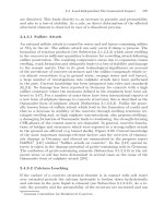
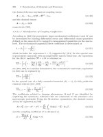
Fig. 3.143. Chemo-mechanical damage of porous materials within the Theory of
Mixtures. Three types of deterioration are illustrated: virgin material, mechanically
damaged material, chemically damaged material and chemo-mechanically damaged
material
3.3.2.2.1 Models for Ion Transport and Dissolution Processes
Authored by Detlef Kuhl and G¨unther Meschke
3.3.2.2.1.1 Introductory Remarks
Based on insights and data obtained from experimental investigations on
calcium dissolution and coupled chemo-mechanical damage processes (see
Subesection 3.1.2.3.2) constitutive models formulated on a macroscopic level
of observation have been developed for the analysis of the time dependent
dissolution process of concrete and concrete structures. One class of mod-
els is based on a phenomenological chemical equilibrium model relating the
calcium concentration of the skeleton and the pore solution s(c) in conjunc-
tion with the concept of isotropic damage mechanics [422], as proposed by
G
´
erard [307] and subsequent publications (G
´
erard [308], G
´
erard et al.
[311], Pijaudier-Cabotetal.[635, 634, 636] and Le Bell
´
ego et al.
[477, 479, 478]).
Ulm et al. [801] and Ulm et al. [799] have proposed a chemo-plasticity
model formulated within the Biot-Coussy-Theory of porous media [211].
This model is also based on a chemical equilibrium model, using empirical
relations for the conductivity and aging. In both models, the irreversible char-
acter of skeleton dissolution is not accounted for. Hence, chemical unloading
or cyclic chemical loading processes cannot be described.
From the experiments the key-role of the porosity for the changing mate-
rial and transport properties of chemo-mechanically loaded cementitious ma-
terials becomes obvious. Based on this observation and in order to consider
296 3 Deterioration of Materials and Structures
the interaction phenomena of chemical and mechanical material degradation
described in Subsection 3.1.2.3.2 a fully coupled chemo-mechanical damage
model has been developed in [454, 455] within the framework of the Theory of
Porous Media. The material is described as ideal mixture of the fully saturated
pore space and the matrix. In this model, the pore fluid acts as a transport
medium for calcium ions. The pore pressure, however, is not accounted for in
the present version of the model.
The changing mechanical and transport properties are related to the to-
tal porosity defined as the sum of the initial porosity, the chemically in-
duced porosity and the apparent mechanical porosity. Together with the
assumptions of chemical and mechanical potentials the need for further as-
sumptions or empirical models is circumvented. Micro-cracks are interpreted
according to Kachanov [422] as equivalent pores affecting, on a macroscopic
level, the conductivity and stiffness but not the mass balance. The evolution
of the mechanically and chemically induced porosities are both controlled
by internal parameters. This enables the modeling of cyclic loading condi-
tions and allows a consistent thermodynamic formulation of the coupled field
problems [454].
The link between the mechanical and the chemical field equations is ac-
complished by the definition of the total porosity φ as the sum of the initial
porosity φ
0
, the porosity due to matrix dissolution φ
c
and the apparent me-
chanical porosity φ
m
:
φ = φ
0
+ φ
c
+ φ
m
. (3.177)
The chemically induced porosity φ
c
can be calculated by multiplying the
amount of dissolved calcium of the skeleton s
0
− s by the averaged molar
volume of the skeleton constituents M/ρ
φ
c
=
M
ρ
[s
0
− s] , (3.178)
where s
0
denotes the initial skeleton concentration. The apparent mechan-
ically induced porosity φ
m
considers the influence of mechanically induced
micro pores and micro cracks on the macroscopic material properties of the
porous material. It is obtained by multiplying the scalar damage parameter
d
m
by the current volume fraction of the skeleton 1 −φ
0
− φ
c
φ
m
=[1−φ
0
− φ
c
] d
m
. (3.179)
This definition of the mechanical porosity φ
m
takes into account that micro-
cracking is restricted to the solid matrix material.
3.3.2.2.1.2 Initial Boundary Value Problem
The coupled system of calcium diffusion-dissolution, mechanical deforma-
tion and damage is characterized by the concentration field c of calcium ions
3.3 Modelling 297
in the pore solution and the displacement field u as external variables and
a set of internal variables concerning the irreversible material behavior. The
macroscopic balance of linear momentum is given by:
div σ =0. (3.180)
The matrix dissolution-diffusion problem is governed by the macroscopic bal-
ance of the calcium ion mass in the representative elementary volume
div q
c
+[[φ
0
+ φ
c
] c ]
·
+˙s =0, (3.181)
whereby q
c
is the mass flux of the solute. The term [[φ
0
+ φ
c
] c ]
·
accounts for
the change of the calcium mass due to the temporal change of the porosity
and the concentration, which is up to one dimension smaller compared to the
calcium mass production resulting from the dissolution of the skeleton ˙s [452].
The system of differential equations (3.180)-(3.181) is completed by bound-
ary conditions on the boundary Γ given by
σ · n = t
, q
c
· n = q
c
, u = u
,c= c
(3.182)
and initial conditions in the domain Ω given by
u(t =0)=u
0
,c(t =0)=c
0
, (3.183)
where q
c
is the calcium ion mass flux across the boundary and c
is the
prescribed concentration.
3.3.2.2.1.3 Constitutive Laws
The elasto-damage constitutive law is characterized by the free energy func-
tion Ψ
m
:
Ψ
m
=
1 −φ
2
ε : C
C
C
s
: ε . (3.184)
Herein, ε denotes the linearized strain tensor and C
C
C
s
is the fourth order elas-
ticity tensor of the the skeleton. The derivative of the free energy function Ψ
m
with respect to the strain tensor ε yields the stress tensor σ:
σ =
∂Ψ
m
∂ε
=[1− φ] C
C
C
s
: ε . (3.185)
The diffusion-dissolution problem is defined by the dissipation potential Ψ
c
of
the calcium ions in the representative elementary volume
Ψ
c
=
φD
l
2
γ · γ , (3.186)
298 3 Deterioration of Materials and Structures
where γ = −∇c is the negative gradient of the concentration field. The deriva-
tive of the dissipation potential Ψ
c
with respect to the negative concentration
gradient γ results in the calcium ion mass flux vector q
c
q
c
=
∂Ψ
c
∂γ
= φD
l
γ (3.187)
of the pore fluid, which is discussed in the next subsection. In eqs. (3.186) and
(3.187) D
0
denotes the second order conductivity tensor of the pore fluid.
Consequently, the macroscopic conductivity of the porous material is given
by D =φD
0
. φ =φ
0
defines the chemical and mechanical sound macroscopic
material (φ
c
= φ
m
= 0), characterized by the subscript s. Hence, the macro-
scopic conductivity of the virgin material is given by D
s
=φ
0
D
0
. In contrast
to existing reaction-diffusion models describing calcium leaching, the depen-
dence of D
0
on the square root of the calcium concentration within the pore
fluid is considered. This dependency follows from Kohlrausch’s law, describ-
ing the molar conductivity of strong electrolytes (see Atkins [66] and Section
3.3.2.2.1.4), using Nernst-Einstein’s relation. In the isotropic case, the con-
ductivity tensor D
0
is given in terms of the second order identity tensor 1,
the calcium ion conductivity for the infinitely diluted solution D
00
≥ 0and
the constant D
0c
≥0.
D
0
= D
0
1 =
D
00
− D
0c
√
c
1 (3.188)
It can be observed, that the conductivity decreases with an increasing cal-
cium concentration. This follows from the interaction of moving cations Ca
2+
and anions OH
−
by electrostatic forces and viscous forces. For D
0c
=0
Kohlrausch’s law (3.188) degenerates to Fick’s law [280] of independent
diffusing particles.
3.3.2.2.1.4 Migration of Calcium Ions in Water and Electrolyte Solutions
The molar conductivity Λ of a strongly electrolyte solution is given as
function of the calcium ion concentration in the pore fluid c by the empirical
Kohlrausch law, see Kohlrausch [436].
D
0
= D
0
1 =
RT
z
2
F
2
Λ 1
Λ = Λ
0
− Λ
c
√
c (3.189)
Herein, R =8.31451J/Kmol is the universal gas constant, T is the to-
tal temperature chosen as T = 298K, z = 2 is the number of elementary
charges of a cation Ca
2+
, F =9.64853·10
4
C/mol is the Faraday constant,
Λ
0
=11.9 ·10
−3
Sm
2
/mol is the molar conductivity at infinite dilution and
Λ
c
is the Kohlrausch constant of the molar conductivity. Based upon the
model of ionic clouds, the Debye-H
¨
uckel-Onsager theory (Debye &
H
¨
uckel [230] and Onsager [602]) verifies Kohlrausch’s law and allows to
determine the Kohlrausch constant Λ
c
,
3.3 Modelling 299
fluid conductivity D
0
macroscopic conductivity φD
0
c
0 5 10 15 20 25
D
0
0
2
6
8
323K
273K
D
0c
=0, T = 298
D
0c
=0, T = 298
T =273K, T =323K
κ
c
/c
0
φ
0.0 0.725
0.2 0.497
0.4 0.457
0.6 0.430
0.8 0.414
1.0 0.200
c
0 5 10 15 20 25
φD
0
0
2
6
8
κ
c
c
0
0.0
0.2
0.8
1.0
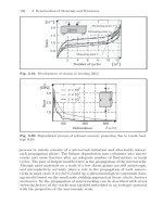
Fig. 3.144. Conductivity of the pore fluid D
0
[10
−10
m
2
/s] as function of the cal-
cium concentration c [mol/m
3
] and the total temperature T [K]. Macroscopic con-
ductivity of non-reactive porous media φD
0
[10
−10
m
2
/s] as function of the calcium
concentration c [mol/m
3
] and the porosity φ [−]withφ=φ(κ
c
,d
m
=0)
Λ
c
= A + BΛ
0
A =
z
2
eF
2
3 πη
2
RT
B =
qz
3
eF
2
24 πηRT
2
RT
(3.190)
where the constants A and B account for electrophoretic and relax-
ation effects associated with the ion-ion interactions. These constants are
given in terms of the universal gas constant, the total temperature, the
elementary charge e =1.602177·10
−19
C, the constant q =0.586, the electric
permittivity =6.954·10
−10
C
2
/Jm and the viscosity η =0.891·10
−3
kg/ms of
water (see e.g. Atkins [66]). From comparing equations (3.188) and (3.189)
the macroscopic diffusion constants D
00
and D
0c
can be determined.
D
00
=
RT
z
2
F
2
Λ
0
= 791.8·10
−12
m
2
s
(3.191)
D
0c
=
RT
z
2
F
2
Λ
c
=96.85·10
−12
m
2
s
m
3
mol
(3.192)
In the present model the macroscopic diffusion coefficient φD
0
can be deter-
mined for any state of chemo-mechanical degradation characterized by the
history variables κ
c
and κ
m
and for any concentration c.
Figure 3.144 contains plots of the conductivity D
0
in the pore fluid and
the macroscopic conductivity φD
0
vs. the calcium concentration within the
300 3 Deterioration of Materials and Structures
range c = 0 corresponding to pure water and c = c
0
corresponding to the
concentrated pore solution of the virgin material. The diagrams on the left
hand side of Figure 3.144 underline the relevance of using higher order ion
transport models, considering electrophoretic and relaxation effects, as a ba-
sis for realistic calcium leaching models. Standard and higher order transport
models are characterized by D
0c
=0 and D
0c
=0, respectively. A pronounced
change of the conductivity D
0
proportional to the square root of the con-
centration c can be observed within the considered concentration range. The
ratio of the conductivities related to the fully degraded material D
0
(0) and
the virgin material D
0
(c
0
) is approximately 9 : 4. The average value of the
conductivity D
0
is approximately D
0
≈ 4·10
−10
m/s
2
. This is in accordance
with the suggestion by Delagrave et al. [232], that in numerical analyses
D
0
/2 should be used as the macroscopic conductivity in order to fit exper-
imental results. Standard transport models are not capable to capture the
significant increase of the conductivity with a decreasing calcium ion con-
centration corresponding to propagating chemical damage in reactive porous
media. As expected, the results of the standard model and the present model
are identical in the case of infinitely diluted solutions (c = 0). The sensitiv-
ity of the ion transport with regards to temperature changes is studied by
including plots of the conductivity for T =273 K, corresponding to the freez-
ing point of water (no calcium ion transport occurs below this temperature),
and for T = 323 K, representing approximately a desert climate, in Figure
3.144. According to equations (3.188), (3.191) and (3.192), the conductivity
D
0
depends linearly on the total temperature T . Within the considered tem-
perature interval D
0
is only changed by approximately 16%. Compared to the
influence of the concentration the influence of the temperature plays a minor
role in the transport process of ions within the pore water of cementitious
materials.
On the right hand side of Figure 3.144, the macroscopic conductivity is
plotted for various values of the threshold calcium concentration κ
c
and the
corresponding values of the porosity, respectively, assuming a non-reactive
porous material.
3.3.2.2.1.5 Evolution Laws
According to Simo & Ju [744] the evolution of the damage parameter
d
m
(κ
m
) is described by the damage criterion
Φ
m
= η(ε) −κ
m
≤ 0 , (3.193)
where η and κ
m
are the equivalent strain function and the internal vari-
able defining the current damage threshold. From the Kuhn-Tucker load-
ing/unloading conditions and the consistency condition
Φ
m
≤ 0 , ˙κ
m
≥ 0 ,Φ
m
˙κ
m
=0,
˙
Φ
m
˙κ
m
=0, (3.194)
3.3 Modelling 301
follows, that κ
m
is unchanged for Φ
m
< 0 and calculated as κ
m
= η otherwise.
The description of the elasto-damage material model is completed by the
definition of the equivalent strain η and the damage function d
m
.Herethe
equivalent strain measure proposed by de Vree et al. [814] is used
η =
k
s
− 1
2k
s
[1 −ν
s
]
I
1
+
1
2k
s
[k
s
− 1]
2
[1 −2ν
s
]
2
I
2
+
12k
s
[1 + ν
s
]
2
J
2
, (3.195)
in which I
1
=tr[ε], I
2
=[tr
2
[ε] − ε : ε]/2andJ
2
=[ε
dev
: ε
dev
]/2arethe
first and the second invariant of the strain tensor ε and the second invariant
of the strain deviator ε
dev
, respectively. The parameter k
s
denotes the ratio
of tensile to compressive strength and ν
s
the Poisson’s ratio of the skeleton.
The exponential damage function is given by
d
m
=1−
κ
0
m
κ
m
1−α
m
+α
m
exp[β
m
[κ
0
m
−κ
m
]]
, (3.196)
where κ
0
m
is the initial damage threshold and α
m
, β
m
are material parameters.
The state of the chemically induced degradation of the porous material is
characterized by the chemical porosity φ
c
(s). Starting from a chemical equi-
librium state between the calcium solved in the pore fluid and the calcium
bound in the skeleton, the dissolution process requires a decreasing concen-
tration c in the pore fluid. Otherwise, if c is increased, the structure of the
skeleton is unchanged. In order to describe chemically induced degradation
similarly to the elasto-damage problem, an internal variable κ
c
is introduced,
which corresponds to the current chemical equilibrium state. Based on this
internal variable κ
c
, the chemical reaction criterion Φ
c
is formulated as
Φ
c
= κ
c
− c ≤ 0 . (3.197)
AccordingtotheKuhn-Tucker conditions and the consistency condition
Φ
c
≤ 0 , ˙κ
c
≤ 0 ,Φ
c
˙κ
c
=0,
˙
Φ
c
˙κ
c
=0, (3.198)
the process of matrix dissolution is associated with a decreasing chemical
equilibrium calcium concentration ( ˙κ
c
≤ 0). The dissolution threshold κ
c
is
unchanged for Φ
c
< 0 and equal to the current calcium concentration of the
pore fluid (κ
c
= c) otherwise. The conditions (3.197) and (3.198) for the
occurence of chemical reactions are identical to those given by Mainguy &
Coussy [512]. This identity is shown in Kuhl et al. [454].
As already mentioned, the current state of the calcium concentration in
the skeleton s is controlled by the spontaneous calcium dissolution. It can
be described as a function of the chemical equilibrium threshold κ
c
given by
G
´
erard [307, 308] and Delagrave et al. [232])
302 3 Deterioration of Materials and Structures
s
0
s
h
c
0
c
p
c
csh
Porefluid Concentration c
[
mol
/
m
3
]
Skeleton Concentration s [kmol/m
3
]
2
5
20151050
16
14
12
10
8
6
4
2
0
✛
dissolution
Fig. 3.145. Chemical equilibrium function by G
´
erard [307, 308] and Delagrave
et al. [232]
s = s
0
− [1 − α
c
] s
h
1 −
1
10
κ
c
+
1
400
κ
2
c
−
s
0
− s
h
1+
κ
c
c
p
n
−
α
c
s
h
1+
κ
c
c
csh
m
(3.199)
for 0 <κ
c
<c
0
and s = s
0
for κ
c
≥ c
0
. α
c
, n and m are model parameters. c
0
and s
0
are the initial equilibrium concentrations of the sound material, c
p
and
c
csh
are material constants related to the averaged fluid calcium concentration
of the progressive dissolution of the portlandite and the CSH phases, s
h
is the
solid calcium concentration related to the portlandite-free cement matrix. A
plot of function (3.199) and an illustration of the material parameters are
given in Figure 3.145.
3.3.2.2.2 Models for Expansive Processes
Authored by Falko Bangert and G¨unther Meschke
3.3.2.2.2.1 Introductory Remarks
Several numerical models have been developed in order to characterize the
observed behavior of concrete affected by the Alkali-Silica Reaction (ASR)
on a material level or even a structural level. Depending on the level of ob-
servation these models follow either a mesoscopic or a macroscopic approach.
A mesoscopic approach involves the analysis of a single representative ag-
gregate particle and its vicinity, whereby the kinetics of the chemical and
diffusional processes involved are described on the scale of the aggregates, see
e.g. Baˇzant & Steffens [96]. On the other hand, in a macroscopic approach
concrete is described at the scale of laboratory specimens, see e.g. Larive &
3.3 Modelling 303
φ
s
= φ
u
φ
l
φ
g
φ
r
φ
u
⎫
⎪
⎪
⎬
⎪
⎪
⎭
φ
s
= φ
r
+ φ
u
φ
l
φ
g
φ
s
= φ
r
φ
l
φ
g
Volume fractions
Microstructure
ϕ
l
ϕ
g
ϕ
u
ϕ
r
t =0 t>0 t →∞
Fig. 3.146. Microstructure, constituents and volume fractions of concrete as a
partially saturated porous media: light gray → unreacted part of the skeleton, dark
gray → reacted part of the skeleton, white → pore gas, black → pore liquid
Coussy [470]. In these models, the main characteristics of ASR are incorpo-
rated phenomenologically on the macroscopic level. Hence, they can directly
be used for numerical analysis of concrete structures [798].
Concluding from Subsection 3.1.2.3.3, there are two main mechanisms that
have to be taken into account for a computational model which allows for real-
istic predictions of concrete deterioration caused by ASR. Firstly, the gel for-
mation by the non-instantaneous dissolution of silica and secondly the swelling
of the gel by the instantaneous imbibition of water. Both processes strongly
depend on the moisture content within the concrete since water acts as a
transport medium of ions and as a necessary compound for the formation
of the swollen gel. Only very limited information on the properties of the
individual constituents on the microscale, in particular of the gel, is available.
In a chemo-hygro-mechanical damage model for the simulation of dam-
age induced by the Alkali-Silica Reaction of concrete developed by [83, 81]
the Theory of Porous Media (see e.g. Ehlers [254], Lewis & Schrefler [493])
together with a geometrically linear kinematics is used as the macroscopic con-
tinuum mechanics framework for the numerical simulation of concrete struc-
tures affected by the Alkali-Silica Reaction. Concrete is modeled as a partially
saturated porous material consisting of a mixture of three main superim-
posed and interacting constituents ϕ
α
, namely the non-porous skeleton (index
α = s), the pore liquid (index α = l) and the pore gas (index α = g). When
the alkali-silica reaction has not yet started (t=0), the skeleton represents a
mixture of the unreacted aggregates and the hydration products. During the
alkali-silica reaction, mass of the aggregates passes non-instantaneously into
mass of the gel. The model formulation is based on the idea, that the gel
formation is initiated at the surface of the aggregate particles and progresses
304 3 Deterioration of Materials and Structures
from the surface inward the particles. It is assumed, that the gel, which is re-
sponsible for the pressure build-up and the macroscopic expansion, is trapped
at the reaction sites inside the reacting aggregate particles. The possibility,
that the expansive gel may permeate in pores and cracks in the cement paste
located near the surface of the aggregate particles or even may diffuse away
through the connected pores space according to a through-solution mecha-
nism is not explicitly considered in this model [83, 81]. Thus, for an instant
t>0 the skeleton ϕ
s
is regarded as a mixture of the unreacted portion of the
aggregates, the gel and the hydratation products.
ϕ
s
= ϕ
u
+ ϕ
r
(3.200)
At the same time, the pore space is solely saturated by the pore liquid ϕ
l
and
the pore gas ϕ
g
. The unreacted phase ϕ
u
represents the unreacted, unswollen
skeleton material before it was affected by the alkali-silica reaction. On the
other hand the reacted phase ϕ
r
represents the reacted, swollen skeleton ma-
terial after completion of ASR. The reactive aggregates of the reacted phase
ϕ
r
are completely converted into a gel. During the alkali-silica reaction, mass
of the unreacted phase ϕ
r
passes non-instantaneously into mass of the reacted
phase ϕ
r
. The mass exchange, which phenomenologically represents the gel
formation by the dissolution of silica, is illustrated in Figure 3.146. At time
t = 0 the skeleton is not affected by ASR as is indicated by the light gray
color corresponding to unreacted material. At an instant t>0 the dark gray
part of the skeleton has already been affected by ASR. Finally, for t →∞the
entire skeleton is affected by ASR.
Following the standard concepts of the Theory of Porous Media, it is as-
sumed, that the constituents ϕ
α
are homogenized over a representative volume
element, which is occupied by the mixture ϕ = ϕ
s
+ ϕ
l
+ ϕ
g
. Therefore, ma-
terial points of each constituent ϕ
α
exist at each geometrical point x. Hence,
the local composition of the mixture ϕ is described by the volume fraction
φ
α
, which is defined as the ratio of the volume element dv
α
occupied by the
individual constituent ϕ
α
and the volume element dv occupied by the mixture
ϕ (see Figure 3.146):
φ
α
=
dv
α
dv
. (3.201)
Since the solid skeleton is regarded as a binary mixture, the respective volume
fraction φ
s
is given as the sum of the volume fraction of the unreacted volume
fraction φ
u
and the reacted volume fraction φ
r
:
φ
s
= φ
u
+ φ
r
. (3.202)
It follows from definition (3.201), that the saturation condition must hold:
φ
s
+ φ
l
+ φ
g
=1. (3.203)
3.3 Modelling 305
The material density
α
and the partial density ρ
α
of the constituent ϕ
α
are
introduced as
α
=
dm
α
dv
α
,ρ
α
=
dm
α
dv
=
dv
α
dv
dm
α
dv
α
= φ
α
α
. (3.204)
Herein, dm
α
denotes the local mass of the volume element dv
α
. The partial
density of the skeleton is assumed to be composed by an unreacted and a
reacted part:
ρ
s
= φ
s
s
= φ
u
u
+ φ
r
r
. (3.205)
For the material densities of the unreacted and the reacted material the
relationship
u
>
r
(3.206)
is assumed. By means of equation (3.206) it is considered, that during the non-
instantaneous gel formation represented by the mass exchange between ϕ
u
and
ϕ
r
the gel swells instantaneously. In other words, the ratio
u
/
r
represents
phenomenologically the volume increase of the gel by the imbibition of water.
The amount of water imbibed by the gel and consequently the ratio
u
/
r
strongly depend on the moisture content of the concrete. Since according
to equation (3.206) the material densities of the unreacted and the reacted
material are different, a variation of the volume fractions φ
u
and φ
r
due
to the aforementioned mass exchange results in a variation of the material
density of the skeleton
s
, see equations (3.202) and (3.205). Thus, the ASR-
induced swelling of the skeleton is associated with the variation of the material
density
s
.
3.3.2.2.2.2 Balance Equations
Investigations on the role of water in the alkali-silica reaction have shown,
that reactive concrete specimens do not absorb significantly more water than
non-reactive ones, when they are stored under the same hygral conditions
[469, 471]. Thus, no specific model needs to be developed to predict water
movement in ASR affected concrete and it is reasonable to neglect any mass
exchange between the skeleton and the pore fluids. In doing so, the mass
balance equation of the skeleton ϕ
s
as binary mixture reads [254]
(φ
s
s
)
s
+ φ
s
s
div(x
s
)=
∂[φ
s
s
]
∂t
+div(φ
s
s
x
s
)=0, (3.207)
where (•)
α
= ∂(•)/∂t +grad(•) · x
α
denotes the material time deriva-
tive of the quantity (•) following the individual motion of the respective
constituent ϕ
α
.
306 3 Deterioration of Materials and Structures
Assuming incompressible constituents ϕ
u
and ϕ
r
of the skeleton ϕ
s
(→
u
=const.,
r
=const.), the associated partial mass balance equations of the
unreacted and reacted phase result in the following volume balance equations:
∂φ
u
∂t
+div(φ
u
x
s
)=
∂φ
u→r
∂t
,
∂φ
r
∂t
+div(φ
r
x
s
)=
∂φ
r←u
∂t
. (3.208)
The terms
u
∂φ
u→r
/∂t and
r
∂φ
r←u
/∂t represent the mass exchange be-
tween the phases ϕ
u
and ϕ
r
due to the dissolution process. Since the summa-
tion of the partial balances (3.208)
1
and (3.208)
2
must result in the mixture
balance equation (3.207), the following constraint must hold:
u
∂φ
u→r
∂t
+
r
∂φ
r←u
∂t
=0. (3.209)
Proceeding with the assumption, that the kinetics of the dissolution of silica
and consequently the mass exchange between the constituents ϕ
u
and ϕ
r
follow a first order kinetic law, one may write (e.g. Atkins [66])
∂φ
u→r
∂t
= −kφ
u
,
∂φ
r←u
∂t
= −
u
r
∂φ
u→r
∂t
=
u
r
kφ
u
, (3.210)
whereby the parameter k is the reaction velocity. Inserting the equations
(3.210) into the volume balance equations (3.208) and neglecting the skeleton
velocity
x
s
≈ 0 , (3.211)
yields:
∂φ
u
∂t
= −kφ
u
,
∂φ
r
∂t
=
u
r
kφ
u
. (3.212)
For constant environmental conditions the volume balance equations (3.212)
can be integrated analytically with the initial value φ
u
0
= φ
s
0
leading to
φ
u
= φ
u
0
[1 −ξ] ,φ
r
=
u
r
φ
u
0
ξ, (3.213)
where ane overall reaction extent ξ has been used. Finally, inserting (3.213)
into (3.205) yields the material density of the skeleton
s
as a function of the
reaction extent ξ:
s
=
u
r
r
+ ξ [
u
−
r
]
. (3.214)
Thus, expression (3.214) reflects the swelling state of the skeleton ranging
from an unswollen state (ξ =0⇒
s
=
u
), if the alkali-silica reaction has
3.3 Modelling 307
not yet started, to a fully swollen state (ξ =1⇒
s
=
r
)aftertheASR
process has come to an end.
In analogy to equation (3.207), the mass balance equations of the pore
fluids ϕ
β
(index β = l → liquid phase, index β = g → gas phase) are given
by:
∂[φ
β
β
]
∂t
+div(φ
β
β
x
β
)=0. (3.215)
Neglecting the material compressibility of the pore liquid in comparison to
the material compressibility of the pore gas (→
l
= const.), and using the
assumption (3.211) one obtains from equation (3.215):
∂φ
l
∂t
+div(φ
l
w
l
)=0,
∂[φ
g
g
]
∂t
+div(φ
g
g
w
g
)=0. (3.216)
The partial momentum balances for the quasi-static case with the body forces
neglected are given by:
div(σ
α
)+
ˆ
p
α
=0. (3.217)
Herein, σ
α
is the partial stress tensor and
ˆ
p
α
the momentum production,
which can be interpreted as the local interaction force per unit volume between
ϕ
α
and the other constituents. Thereby the following constraint
ˆ
p
s
+
ˆ
p
l
+
ˆ
p
g
= 0 (3.218)
must hold due to the overall conservation of momentum
div(σ)=0, (3.219)
with the overall stress tensor σ = σ
s
+ σ
l
+ σ
g
.
3.3.2.2.2.3 Constitutive Laws
Theporespaceofconcreteφ
l
+ φ
g
is partially saturated with liquid and
partially with gas, see Figure 3.146. The degree of liquid and gas saturation
s
β
, respectively, is given by:
s
β
=
φ
β
φ
l
+ φ
g
. (3.220)
The pore liquid and the pore gas are separated by a curved interface (menis-
cus) because of surface tensions. The radius of curvature of this interface
depends on the pressure jump across the interface expressed by the so-called
capillary pressure p
c
:
p
c
= p
g
− p
l
. (3.221)
308 3 Deterioration of Materials and Structures
In what follows, however, the capillary pressure p
c
will be interpreted as a
macroscopic pressure representing all hygrally induced stresses acting on vari-
ous scales of the nano-porous cementitious material, see e.g. [97]. There exists
a relationship between the water content of the porous medium expressed by
the liquid saturation s
l
and the capillary pressure p
c
.In[83]thefollowing
expression for the capillary pressure p
c
as a function of the liquid saturation
s
l
is used
p
c
= p
r
s
l
−
1
m
− 1
1
n
, (3.222)
according to van Genuchten [306]. In equation (3.222), p
r
, n, m denote ma-
terial parameters, which have to be determined experimentally. The relation
(3.222) has been originally proposed for soils. However, the p
c
(s
l
)-relations
determined experimentally by Baroghel-Bouny et al. [88] for different
types of cementitious materials by means of water vapor sorption isotherms
are well fitted by expression (3.222).
From thermodynamical considerations follows that the stress state of the
skeleton and the fluid constituents is separated into two parts, where the
first part is governed by the skeleton deformation and the pore fluid flow,
respectively, while the second part is governed by the pore pressures (see e.g.
[254]):
σ
s
= σ
s
− φ
s
p 1 , σ
β
= σ
β
− φ
β
p
β
1 . (3.223)
Therein, the pore pressure p is given by Dalton’s law
p = s
l
p
l
+ s
g
p
g
, (3.224)
where p
l
denotes the unspecified liquid pressure, whereas the gas pressure p
g
is related to the material density
g
by the following constitutive law for an
ideal gas:
g
=
M
g
RT
p
g
. (3.225)
In equation (3.225), M
g
denotes the molar mass of the pore gas, R the uni-
versal gas constant and T the absolute temperature.
The overall stress tensor σ of the porous material is given by the sum of
the partial stress tensors σ
α
according to (3.223):
σ = σ
s
+ σ
l
+ σ
g
− p 1 . (3.226)
In the Theory of Porous Media the fluid frictional stresses σ
β
are usually
neglected (σ
β
≈ 0), yielding the well known concept of effective stress (see
Bishop [127]):
σ = σ
s
− p 1 . (3.227)
3.3 Modelling 309
For the modeling of brittle failure of the skeleton (reduction of stiffness
and strength) the continuum damage theory proposed by Kachanov [422] is
employed.
According to the effective area concept by Kachanov [422], the scalar dam-
age parameter d can be interpreted as the ratio of the damaged cross section
and the initial cross section. Thus, the undamaged material is characterized
by d = 0, while d = 1 corresponds to the complete loss of integrity. Since the
stresses in the skeleton are transferred by the intact, undamaged cross section,
the effective stress reads
σ
s
=[1−d] φ
s
0
C
C
C
s
:[ε
s
− ε
a
s
1] , (3.228)
with the effective elasticity tensor of the skeleton C
C
C
s
= E
s
[I
I
I + ν
s
/[1 −2ν
s
]1 ⊗
1]/[1 + ν
s
], defined in terms of the Young’s modulus E
s
and the Poisson’s
ratio ν
s
. In equation (3.228), the volumetric expansion resulting from ASR is
considered by the volumetric strain ε
a
s
. As mentioned above, the ASR swelling
of the skeleton results from the variation of the material density
s
of the
skeleton, compare equation (3.214). Therfore, the volumetric expansion ε
a
s
is
defined as
ε
a
s
=
s
0
s
− 1 , (3.229)
where
s
0
denotes the initial material density of the skeleton. There is an ongo-
ing debate whether the gel formed by the dissolution of silica initially saturates
the pores in the cement paste located near the surface of the aggregates before
a expansive pressure builds up (see Section 3.1.2.3.3). The definition 3.229 of
the ASR-expansion implies, that the gel is trapped at the reaction sites inside
the aggregates, thus representing a part of the skeleton. Consequently, the lo-
cal ASR-progress directly results in the deformation of the skeleton. However,
an initiation period due to a filling process can be considered by the model by
introducing an initiation threshold for the ASR-expansion as e.g. suggested
by Steffens et al. [772].
In the model proposed by [83], an isotropic damage model characterized
by a single damage parameter d and a strain based description of the dam-
age evolution in the sense of Simo & Ju [744] is used (see Section 3.3.1.2.2).
Since the local continuum description of material degeneration suffers from the
loss of well-posedness beyond a certain level of accumulated damage resulting
in unphysical numerical results, a gradient enhanced damage formulation as
proposed by Peerlings et al. [614] is used as a means of regularization. The
evolution of damage is governed by the deformation of the skeleton. According
to Simo & Ju [744] an internal variable κ is introduced, which represents the
most severe deformation the skeleton material has experienced in the previ-
ous loading history and which acts as a threshold below which there is no
further damage evolution. The damage parameter d is an explicit function of
the internal variable κ. The evolution of κ is governed by the damage criterion
310 3 Deterioration of Materials and Structures
Φ =¯η − κ ≤ 0 , (3.230)
where ¯η denotes the non-local equivalent strain. From the Kuhn-Tucker load-
ing / unloading conditions and the consistency condition
Φ ≤ 0 ,
∂κ
∂t
≥ 0 ,Φ
∂κ
∂t
=0,
∂Φ
∂t
∂κ
∂t
= 0 (3.231)
follows, that κ is unchanged for Φ<0 and calculated by κ =¯η otherwise.
The non-local equivalent strain ¯η in equation (3.230) is calculated on the
basis of the following partial differential equation:
η =¯η − div(g grad(¯η)) . (3.232)
In this equation, η denotes the (local) equivalent strain representing a scalar
measure of the local deformation state. Due to the gradient parameter g with
the dimension of length squared an internal length scale is present in the
formulation, which avoids the loss of well-posedness mentioned above.
Finally, the equivalent strain η and the damage parameter d must be spec-
ified. Here, the equivalent strain measure corresponding to the Rankine crite-
rion of maximal principal stress is used [83]:
η =
1
E
s
max < ˜σ
s
i
>, i =1, 2, 3 , (3.233)
with max < ˜σ
s
i
> denoting the positive part of the largest eigenvalue of the
undamaged effective stress tensor
˜
σ
s
.
The definition of the effective stress tensor σ
s
according to equation (3.228)
is based on the assumption, that deterioration due to ASR only takes place if
the ASR expansion ε
a
s
is hindered. If the concrete can expand freely (σ
s
= 0
→ ε
s
= ε
a
s
1), the stiffness and strength are not affected by the alkali-silica
reaction. This assumption, which is used for most model formulations in the
literature [632, 798, 772], implies, that the degradation of concrete caused
by ASR is mainly induced by structural effects. These structural effects may
result from hindered deformations due to geometrical constraints or from gra-
dients in the ASR expansion following from a non-uniform moisture distribu-
tion. It should be mentioned, that even under stress-free conditions (σ
s
= 0)
microcracks can develop in the vicinity of the aggregate particles e.g. due
to geometrical incompatibilities. However, on the macroscopic level the struc-
tural effects have a much more severe influence on the deterioration of concrete
structures than these microcracks on the level of the aggregate particles.
Although the fluid frictional stresses σ
β
are neglected, the fluid viscosity
is included via the momentum production terms
ˆ
p
β
in the partial momentum
balance equations (3.217). These are chosen as
ˆ
p
β
= p
β
grad(φ
β
) −
φ
β
2
μ
β
k
β
w
β
, (3.234)
3.3 Modelling 311
with the dynamic viscosity μ
β
and the permeability k
β
[254]. In turn, the
permeability k
β
depends on the intrinsic permeability k
0
and on the non-
dimensional scaling factor k
β
r
, which takes the dependence of the permeability
k
β
on the saturation into account:
k
β
= k
β
r
k
0
. (3.235)
The intrinsic permeability k
0
represents the permeability of the fully saturated
porous material, which is independent of the saturating fluid phase. The in-
fluence of the saturation is considered according to van Genuchten [306]
k
l
r
=
√
s
l
1 −
1 −
s
l
1
m
m
2
,k
g
r
=
1 −s
l
1 −
s
l
1
m
2m
,
(3.236)
where m is the same material parameter as used in the capillary pressure
relation (3.222).
Finally, inserting the momentum productions
ˆ
p
β
(3.234) into the related
momentum balance equations (3.217) yields Darcy’s law:
φ
β
w
β
= −
k
β
μ
β
grad(p
β
) . (3.237)
By inserting the result into the partial mass balance equations of the pore flu-
ids (3.216), the seepage velocities w
β
can be eliminated as primary variables.
3.3.2.2.2.4 Model Calibration
In this paragraph, the calibration of the chemical material parameters
u
,
r
and k, which control the deterioration caused by the alkali-silica reaction
is described.
First, a stress-free expansion test (σ = 0) of a reactive concrete specimen
carried out at a certain temperature and humidity is considered. Inserting
equation (3.228) into equation (3.227) yields after re-arrangement:
ε
s
= ε
a
s
1 +
1
[1 −d] φ
s
0
[C
C
C
s
]
−1
: p 1 . (3.238)
For iso-hydro-thermal laboratory conditions the second part on the right hand
side of equation (3.238) is almost constant since the pore pressure p does
not change significantly in the course of the alkali-silica reaction. Hence, in
laboratory tests on ASR affected concrete only the part ε
a
s
of the strain tensor
ε
s
is measured, which is governed by the chemical reactions. Inserting the
material density of the skeleton
s
according to equation (3.214) and the
initial value
s
0
=
u
into the ASR expansion ε
a
s
defined in equation (3.229)
yields for constant environmental conditions:
ε
a
s
=
u
r
− 1
ξ. (3.239)
312 3 Deterioration of Materials and Structures
Differentiation of equation (3.239) with respect to time results in:
∂ε
a
s
∂t
=
∂ε
a
s
∂ξ
∂ξ
∂t
= k [1 − ξ]
u
r
− 1
. (3.240)
From equations (3.239) and (3.240) the following values are obtained for the
onset (t =0⇒ ξ = 0) and for the completion of the alkali-silica reaction
(t →∞⇒ξ =1):
ξ =0⇒ ε
a
s
=0,
∂ε
a
s
∂t
= k
u
r
− 1
,
ξ =1⇒ ε
a
s
=
u
r
− 1
,
∂ε
a
s
∂t
=0.
(3.241)
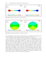
From equations (3.241) together, with the left diagram in Figure 3.147, which
shows a typical strain evolution in a stress-free expansion test, the meaning
of the chemical material parameters becomes clear: The parameter
u
/
r
−1
represents the asymptotic strain in a stress-free expansion test. Furthermore,
the parameter k controls the slope of the respective expansion-time-relation
at the onset of ASR. Hence, the chemical material parameters
u
/
r
−1andk
are well-defined and can be easily determined by means of macroscopic strain
measurements on reactive concrete specimens.
Both chemical material parameters (
u
/
r
− 1andk) depend on the con-
crete mix design, the type of aggregates, the temperature and the moisture
content. In particular, the moisture dependence plays a dominant role in the
ASR deterioration. The role of moisture within the alkali-silica reaction has
been studied in detail in an extensive test campaign at the Laboratoire Cen-
tral des Ponts et Chauss´ees by Larive [469]. In these tests, cylindrical concrete
Test results
1/k
u
/
r
− 1
Time t [d]
Expansion ε
a
s
[%]
4003002001000
0.4
0.3
0.2
0.1
0
Model results
Test results
1/k
u
/
r
− 1
Liquid saturation s
l
[
-
]
Inverse velocit
y
1
/
k
[
d
]
Asymptotic expasion
u
/
r
− 1[%
]
120
90
60
30
0
10.90.80.7
0.6
0.45
0.3
0.15
0
Fig. 3.147. Illustration of the chemical material parameters k and
u
/
r
− 1and
of their dependence on the liquid saturation s
l
according to experimental results by
Larive [469] and to model results by Steffens et al. [772]