Lifetime-Oriented Structural Design Concepts- P7 ppsx
Bạn đang xem bản rút gọn của tài liệu. Xem và tải ngay bản đầy đủ của tài liệu tại đây (4.71 MB, 30 trang )
138 3 Deterioration of Materials and Structures
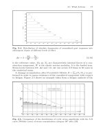
Number of cycles
Strain
Measuring point 2
Measuring point 1
Measuring point 3
Fig. 3.19. Development of strains in bending [662]
Stress
Deformation
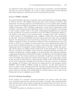
Fig. 3.20. Degradation process of relevant concrete properties due to tensile load-
ings [429]
process in metals consists of a microcrack initiation and afterwards microc-
rack propagation phase. The fatigue degradation may culminate into macro-
cracks and cause fracture after an adequate number of fluctuations or loads
cycles. The part of fatigue modeled here is the propagation of the microcracks.
Altough most materials on a scale of a few dozen grains are still anisotropic,
and microplasticty certainly plays a role in the propagation of such microc-
racks in most cases it is tried to build up a phenomenological continuum dam-
age model based on the small scale yielding approach of linear elastic fracture
mechanics. So the propagation of microcracking can be described with stress
intensity factors of the cracks near tip field embedded in an isotropic material
with the properties of the macroscopic scale.
3.1 Phenomena of Material Degradation on Various Scales 139
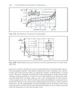
Flexural strength
Related cycle ratio
Fig. 3.21. Degradation process of relevant concrete properties due to flexural load-
ings [866]
Fig. 3.22. Stiffness reduction by high cycle fatigue
Brittle Damage by Microcracks
As in this context only damaging processes caused by microcracks, which
are triggered by elastic stresses, are regarded no macroscopic plasticity has to
be considered. Imagine such a member with growing microcracks undergoing
a process, in which it is deformed by a total deformation, a certain part of this
will be elastically recoverable, and another part can be induced by damage.
When these loads are released, the member will have, in contrast to plastic-
ity, not any remaining permanent deformation. Nevertheless, the state of the
member could have changed; its elastic stiffness could have been reduced by
the growth of microcracks. For a process which involves no further damag-
ing, the total deformation is an elastic one, but starting from a state with
140 3 Deterioration of Materials and Structures
Fig. 3.23. Model for brittle damage by microcrack growth
changed elastic properties. The underlying micromechanics for a continuum
point and the corresponding macro-stresses and strains are sketched in Fig-
ure 3.22. Starting with an unstressed member, containing a crack of length
2a and the resulting average stiffness E (the stiffness of the matrix remains
unchanged by crack growth), up to a certain load the crack will not grow in
length but only open its width. Beyond this threshold the crack length will
increase and the average stiffness decreases. When the member is unloaded
again the crack will close and no further growth occurs. For the same stress a
greater strain will result, due to the reduced stiffness. In the stress free state
there is - as already mentioned - no permanent deformation. Only the stiffness
remains on a lower level than in the initial stage. The free energy W stored at
the end of the process and the energy dissipated by crack growth W
crack
are
also sketched in Figure 3.22. This means the process of stiffness degradation
can be modelled by finding a correct representation for the energy dissipated
by crack growth. This will be the basis for the continuum damage model for
high-cycle fatigue of metals presented in Section 3.3.1.2.2.2.
3.1.2 Non-mechanical Loading
Authored by Otto T. Bruhns and G¨unther Meschke
3.1.2.1 Thermal Loading
Authored by Rolf Breitenb¨ucher and Hursit Ibuk
3.1.2.1.1 Degradation of Concrete Due to Thermal Incompatibility of Its
Components
If the thermal behaviour and the thermal properties of the various concrete
constituents are quite different from each another, in cases of significant
3.1 Phenomena of Material Degradation on Various Scales 141
temperature changes, incompatibilities in the deformations of the different
materials cause internal stresses between the aggregates and the cement paste,
wich further can result in internal cracking. For this purpose the coefficients of
thermal expansion (α
T
-value) of concrete constituents can become important.
However, under normal conditions, in practice, differences in the thermal
expansion coefficient are not necessarily deleterious when the temperature
does not exceed the temperature range of about 4 to 60
◦
C. However, if the
two relevant α
T
-values (aggregates, cement paste) differ seriously (much more
than 5.5 ·10
−6
K
−1
) from each another the durability of concrete concerning
freezing and thawing may be affected [567].
3.1.2.1.2 Stresses Due to Thermal Loading
Much more important for microcracking and degradation processes in concrete
structures are restraint stresses, caused by restraining of thermal deformations
(
T
= α
T
·Δt). Such restraint can be external as well as internal.
In most cases temperature profiles over a cross-section are not constant or
linear, but more or less stochastic and non-linear (Figure 3.24). Thus, the re-
sulting stresses can be divided into longitudinal, warping and internal stresses.
For longitudinal stresses with constant magnitude an external restraint and
constant temperature changes over the cross-section of concrete are respon-
sible. Such an external restraint is caused in practice e.g. by bond to a stiff
foundation or an already hardened concrete member. A linear distributed tem-
perature gradient results in warping stresses, since the bending deformations
usually are restrained already by the deadload or also by external restraint.
Internal stresses are formed by the restraint of non-linear thermal deforma-
tions. In this case the restraint is internal, as the cross-section cannot deform
unevenly (Bernoulli-hypothesis).
In context with restraint stresses due to restrained thermal deformations
especially in thicker concrete members often already the load-case ”heat of
hydration” becomes relevant.
Fig. 3.24. Stresses in a concrete slab at one-sided, non-linear cooling from the top
[145]
142 3 Deterioration of Materials and Structures
3.1.2.1.3 Temperature and Stress Development in Concrete at the Early Age
Due to Heat of Hydration
When concrete has been placed, initially the temperature remains unchanged,
because the hydration process is still in its rest period (stage I) (Figure 3.25).
A few hours after starting of hydration also a moderate temperature raise can
be observed, however (also in case of restraint) without developing significant
compressive stresses. At this stage II the concrete has not yet set and is there-
fore still plastically deformable. Along with further hydration the stiffness of
the concrete increases and may lead – if the deformations are restrained – to
compressive stresses (stage III). The concrete temperature at the beginning
of this third stage is called the first zero-stress temperature (1. T
z
). However,
also in this stage the relaxation of the young concrete is still high, so that
in spite of a significant temperature rise only small compressive stresses are
raised. In the consequence of this high relaxation at the end of stage III the
maximum of the compressive stresses is obtained in general some time before
the temperature maximum. After exceeding the temperature maximum the
remaining compressive stresses decrease rapidly (stage IV). Only a few degrees
below the temperature maximum the second zero-stress temperature (2. T
z
)is
obtained. Already starting from this point tensile stresses are caused during
Time [t]
Time [t]
T
crack
2. T
Z
1. T
Z
T
concrete
Stage
-s
+s
Longitudinal stress Temperature [°C]
I II III
IV V
T=T
air fresh concrete
Fig. 3.25. Temperature and stress development during the first hydration phase in
restrained concrete elements [763, 145, 466]
3.1 Phenomena of Material Degradation on Various Scales 143
further cooling (stage V). When the not yet significantly developed tensile
strength is exceeded in this cooling period, at an age of only a few days, first
cracks will be formed at the so-called cracking-temperature (T
crack
). [145].
Especially in mass concrete structures the internal restraint and thus the
resulting internal stresses can become a dominant cause for thermal cracking.
If the heat of hydration is not controlled and large temperature differences
between the inner core and the surface are raised, internal stresses with tension
at the surface develop in the concrete member. Thus, a surface map-cracking
in the surface-zone can occur, whereby the crack-width usually is very small.
It is evident, that the described cracking also at such thermal loadings doesn’t
develop suddenly. Furthermore it has to be considered, that also in such cases a
complex micro-cracking is preceding the macro-cracking formation. Thus also
by this way degradation processes can take place, even if the tensile strength
is not exceeded, i.e. when the ambient temperature is achieved before macro-
cracks could be formed. In this case the concrete structure remains on a high
tensile stress level and micro cracks (with resulting degradation) develop.
3.1.2.2 Thermo-Hygral Loading
Authored by Max J. Setzer and Rolf Breitenb¨ucher
3.1.2.2.1 Hygral Behaviour of Hardened Cement Paste
Authored by Max J. Setzer and Christian Duckheim
Due to its nano- and microporous structure hardened cement paste inter-
acts strongly with its environmental humidity. This gain or loss of water has
a deep impact on durability and material properties below 0
◦
C (e.g. frost) as
well as above 0
◦
C (e.g. creep and shrinkage) [633]. Even if further research is
required, freeze-thaw-resistance of concrete structures and the corresponding
mechanisms have been investigated extensively in the last years and can be ex-
plained well today. In contrast, despite numerous different analyses creep- and
shrinkage-mechanisms are only fragmentarily understood up to now. Amongst
others, this fact can be attributed to the manifold parameters which influence
experimental results (such as sample composition and shape or the measur-
ing setup and procedure) but most of all to the complex colloidal structure
formed by nano-sized CSH-particles, where only complicated ascertainable
surface interactions play a decisive role. Drying shrinkage and swelling as a
basic hygric property of hardened cement paste (w/c =0, 35; 0, 40; 0, 50 and
0, 60) has been investigated over the complete humidity range by means of
a newly developed laser supported measuring principle. This new technique
allows the speedy, precise measurement of the pure material characteristic
of several filigree samples with an accuracy of about 20 nm. Further mainly
novel methods have been applied for examining sorption behaviour as well as
inner volume and density change. Measurement data have been analysed with
144 3 Deterioration of Materials and Structures
-10
-9
-8
-7
-6
-5
-4
-3
-2
-1
0
0 102030405060708090100
relative humidity (%)
w/c = 0,35 (1st Des.) w/c = 0,35 (1st Ads.)
w/c = 0,40 (1st Des.) w/c = 0,40 (1st Ads.)
w/c = 0,50 (1st Des.) w/c = 0,50 (1st Ads.)
w/c = 0,60 (1st Des.) w/c = 0,60 (1st Ads.)
Fig. 3.26. Hygric strains vs. relative humidity
-10
-9
-8
-7
-6
-5
-4
-3
-2
-1
0
02468101214161820
water content (%)
w/c = 0,40 (1st Des.)
w/c = 0,40 (1st Ads.)
w/c=0,40(2ndDes.)
w/c=0,40(2ndAds.)
Fig. 3.27. Hygric strains vs. relative humidity & vs. water content
respect of the prevailing mechanisms on the nano- and microscale as surface
energy, disjoining pressure and capillary tension.
In Figure 3.26 hygric strains of four samples with different w/c-ratios
during first de- and adsorption are illustrated. Figure 3.27 shows the relation
between the measured deformations (w/c =0, 40) and water content of
3.1 Phenomena of Material Degradation on Various Scales 145
-9
-8
-7
-6
-5
-4
-3
-30 -25 -20 -15 -10 -5 0
surface free energy change (J/g)
w/c = 0,35 (1st Des.) w/c = 0,35 (1st Ads.)
w/c = 0,40 (1st Des.) w/c = 0,40 (1st Ads.)
w/c = 0,50 (1st Des.) w/c = 0,50 (1st Ads.)
w/c = 0,60 (1st Des.) w/c = 0,60 (1st Ads.)
Fig. 3.28. Hygric strains vs. surface free energy change. For further details (calcu-
lation of surface energy and deformations due to capillary tension) see [239]
the structure including a second desorption-adsorption-cycle. The total
deformation, which grows with increasing w/c-ratio, lies in between 7 mm/m
and 9 mm/m. Examining the results, in the range from 0 % r. h. to 100 %
r. h. different sections (desorption: 100% → 35% → 25% → 0%; adsorption:
0% → 60% → 100%) with each varying dominating mechanisms can be
found. A close connection between water content of the structure and studied
properties is demonstrated with only a marginal hysteresis between drying
and wetting as well as the influence of capillary condensation. It could be
proved that in the lower humidity range shrinkage and swelling are indeed
proportional to changes in the surface free energy indeed (Figures 3.28
to 3.31). However, an energy reduction during adsorption does not lead
to an expansion as assumed up to now (Munich Model), but rather to a
contraction of csh-particles (Figure 3.31), while the pore volume increases
simultaneously and vice versa during desorption. Solid density which is
nearly independent from w/c varies between about 2.3g/cm
3
(dry) and
2.5g/cm
3
(wet). For this reason the influence of surface energy has to be
attributed to the dispersive component of disjoining pressure which prevails
in the lower humidity range, whereas in the range of condensation repulsiv
components (electrostatic and structural component) and capillary tension
dominate the processes in hardened cement paste. Consequently here a
distinct linear relation-ship exists between hygric strains and water content
(Figure 3.27). Irreversible strains have to be attributed merely to first
drying.
146 3 Deterioration of Materials and Structures
-5
-4
-3
-2
-1
0
0 102030405060708090100
relative humidity (%)
w/c = 0,35 (calculated)
w/c = 0,35
w/c = 0,40 (calculated)
w/c = 0,40
w/c = 0,50 (calculated)
w/c = 0,50
w/c = 0,60 (calculated)
w/c = 0,60
Fig. 3.29. Hygric strains vs. surface free energy change & comparison between mea-
sured hygric strains and hygric strains calculated by capillary tension. For further
details (calculation of surface energy and deformations due to capillary tension) see
[239]
0
5
10
15
20
25
30
0 102030405060708090100
relative humidity (%)
w/c = 0,35 (1st Des.) w/c = 0,35 (1st Ads.)
w/c = 0,40 (1st Des.) w/c = 0,35 (1st Ads.)
w/c = 0,50 (1st Des.) w/c = 0,50 (1st Ads.)
w/c = 0,60 (1st Des.) w/c = 0,60 (1st Ads.)
Fig. 3.30. Sorption isotherms vs. relative humidity
3.1 Phenomena of Material Degradation on Various Scales 147
2,2
2,3
2,4
2,5
2,6
0 102030405060708090100
relative humidity (%)
w/c = 0,35 (1st Des.)
w/c = 0,35 (1st Ads.)
w/c = 0,40 (1st Des.)
w/c = 0,40 (1st Ads.)
w/c = 0,50 (1st Des.)
w/c = 0,50 (1st Ads.)
w/c = 0,60 (1st Des.)
w/c = 0,60 (1st Ads.)
Fig. 3.31. Solid density vs. relative humidity
The presented findings and additional results are merged in a schematic
diagram (Figure 3.32) which describes the change of various hygric proper-
ties qualitatively and illustrates the effects of the two different mechanisms
(disjoining pressure and capillary tension) on the system of hardened cement
paste during first desorption and adsorption. Elaborate explanations and fur-
ther details can be found in [239].
3.1.2.2.2 Influence of Cracks on the Moisture Transport
Authored by G¨unther Meschke
Cracks, irrespective of their origin, have a considerable influence on the
moisture permeability of cementitious materials. As a consequence, the trans-
port of aggressive substances is promoted and the degradation process is
further accelerated. The significant influence of fracture on the transport prop-
erties of porous materials was first recognized in the context of the coupled
mechanical and hydraulic behavior of fractured rock masses. Experiments by
Zoback & Byerlee [874] indicate an increase of the permeability of granite
caused by microcracking. Particularly for materials with very low moisture
permeabilities, such as granite and shale, flow through the connected pore
space was found to be insignificant compared to flow through fracture zones.
The role of cracks on the transport properties of cement-based materials has
been investigated in e.g. [92, 155, 309, 41, 310], see Breysse and G´erard [153]
for a state-of-the-art survey. It has been shown, that the problems of moisture
transfer change the scale, in fact that the permeability is increased by several
orders of magnitude, when cracking is considered.
148 3 Deterioration of Materials and Structures
Fig. 3.32. Schematic diagram of hygric mechanisms and properties of hardened
cement paste
3.1.2.2.3 Freeze Thaw
Authored by Max J. Setzer and Ivanka Bevanda
Deterioration under freeze thaw attack has been discussed in literature
under various aspects. The most recent development deals with the aspects
of fracture mechanics. But for understanding the damage mechanism of frost
and frost deicing salt attack, it is important to understand the following:
(1) freeze thaw cycles (with and without de-icing salt) acted as a micro
pump and (2) a distinction between the forgoing transport process and the
following damage process and final degradation is essential. The unusual
freezing behaviour of the pore solution in cement paste i.e. the special pore
system is responsible that water and solution will be sucked up during freeze
thaw cycles [723],[725]. This phenomena: (1) frost suction and (2) following
deterioration after reaching the critical degree of saturation explained by
Setzers modul of the micro-ice-lens [725],[727],[728],[730]. This model, based
on the fact that within the concrete matrix water, vapour and ice can
coexist in a wide temperature range, as concrete deviates from macroscopic
behaviour due to its nanostructure. This leads to shrinkage of the gel during
3.1 Phenomena of Material Degradation on Various Scales 149
I: Cooling
pressure due to triple
phase condition
expansion / contraction
liquid water flow
internal vapor transport
bulk-
ice
matrix
gel-
water
Vapor
II: Heating
gel
macro
approx. 150 nm
approx. 150 mm
'
p
T
x
0
x
T'
p
Freezing zone
External heat
Compression zone
only water - vapor
Melting
zone
00
External water
External heat
Expansion zone
0
external
water
Triple phase
Fig. 3.33. Comparison of macroscopic and microscopic situation of the micro-ice-
lens model during the heating and cooling phase [731]. Because of a pressure differ-
ence between the unfrozen gel water and ice in larger pores, water transport occurs,
when freezing starts. Water from the micro pores is transported to existing ice in
capillary pores. Simultaneously shrinkage of smaller pores can be registered. The
water, i.e. ice, content of the macro pores increases. During thawing the gel tries
to expand be again sucking water, which is available not from the still frozen ice
in larger pores but from external sources. Independently with the 9% expansion of
volume of ice, frost damage occurs in completely filled pores
freezing and to transport process within the pore system during melt-
ing (see Figure 3.33).
Powers [644] and Fagerlund [270] particularly describe models of retarded
ice formation which leads to hydraulic pressure. Powers and Helmunt were
the first who discussed the problems arising from transport phenomena, os-
motic and hydraulic pressure [644],[645],[366]. Fagerlund [269] refined this
and stated the distinction between the critical degree and when damage started.
Some models discussed the submicroscopic stress which is generated by sur-
face interaction and by curved surfaces. Everentt and Haynes [266] described
this phenomena as an ice crystal which is successively penetrating a micro pore.
Scherer [699] uses similar semi-macroscopic explanation for the damage pro-
cess. Litvan [503] explained the transport from unfrozen pore water to ice
due to diffusion. The impact of surface forces on frost damage was taken into
150 3 Deterioration of Materials and Structures
account by the thermodymamic model developed by Setzer [723]. One group of
damage models was explained by macroscopically generated stress. Podval-
nyi [640] discussed the influence of thermal expansion of the matrix and the
aggregate, Snyder [759], Bl
¨
umel and Springenschmidt [131] the stress due
to temperature and salt concentration gradients, R
¨
osli and Harnik [689] the
temperature and stress gradient due to sudden melting of ice by de-icing agents.
Besides this, physical models a chemical model for the damage mechanism un-
der frost de-icing salt attack is described in [509],[508]. Ludwig has shown a
preferred formation of ettringite under low temperatures.
It should be noted that it was found in the SFB 398/ TP A11 that
small amounts of dissolved ions increase the surface scaling dramatically (see
Subsection 2.4.2, [120]). This can neither be explained by macroscopic or
semi-macroscopic physics - concentrations are much too small - nor by pure
chemical effects - the phenomena reach a maximum between 0.2 mol/l and 0.5
mol/l. Similar to chromatographic effects during transport both must proba-
bly be attributed to superimposed effects of surface physics.
3.1.2.3 Chemical Loading
Authored by Rolf Breitenb¨ucher, Hursit Ibuk and G¨unther Meschke
3.1.2.3.1 Microstructure of Cementitious Materials
Concrete is a nano-porous multi-component system composed of aggregates
and cement matrix. The cement matrix is consisting of a heterogeneous sys-
tem of non-hydrated cement, hydration products, pores and pore solutions.
It should be noted, that during the hydration process of cement both large
calcium hydroxide crystals and CSH-gel are generated simultaneously result-
ing in a pore structure characterised by a pore size distribution ranging from
capillary pores to gel pores (Figure 3.34). Different mechanical, physical and
chemical processes which may considerably affect the durablity of the material
are caused and controlled by the pore size distribution, the fluid saturation,
the mechanically and chemically induced changes in the porosity and the
chemical composition of the pore fluid and the matrix.
Durability of concrete is highly affected by the transport of moisture
and ionic (corrosive) species eventually leading to damage processes caused
by chemically expansive reactions as well as by dissolution of load bearing
constituents.
The pore size distribution of hardened cement paste covers a large spectrum
of pores extending over 7 orders of magnitude, see Figure 3.34. The smallest
pores are smaller than one nanometre and the sizes of voids due tonon-completed
compaction might exceed some millimetres. Furthermore, at least two different
kinds of pores have to be distinguished: The gel pores resulting from the cement
hydration within these CSH-products and the larger capillary pores in the
cement-paste between the original cement particles. The different pores also may
3.1 Phenomena of Material Degradation on Various Scales 151
Fig. 3.34. Volume fractions of constituents of hardened cement paste as a function
of the water cement ratio [448]
be distinguished according to their behaviour and/or to thenecessary time to ob-
tain a specific capillary pore system [724]. This yields a classification into coarse
pores, capillary pores, meso- and micro-gel pores, see Table 3.1.
Table 3.1. Classification of pore sizes in concrete according to [724]
Type of
pore
Hydr.
radius
Characteristics Type of pore water
Coarse ≥ 1mm empty
Macro-
capillary
< 1 mm sucking, immediately refillable free macroscopic water, freez-
able, highly mobile, small cap-
illary rise.
Meso-
capillary
< 30μm sucking within minutes, refill-
able within weeks
free macroscopic water, freez-
able, considerable capillary rise
within a few days
Micro-
capillary
< 1μm no stationary state macroscopic water, freezable,
strong capillary attraction, but
increasing internal friction
Meso-
gel
< 30 nm Transition from macroscopic
behaviour to surface physics;
filled by condensation at 50 % to
98 % rel. humidity
pre-structured, condensed wa-
ter, evaporation below 50 % rel-
ative humidity, not freezable be-
yond −23
◦
C
Micro-
gel
< 1 nm surface physics, filled by sorp-
tion below
< 50 % relative humidity
structured surface water,
strongly disturbed, not freez-
able
152 3 Deterioration of Materials and Structures
Table 3.2. Influences on the degree of chemical attack
Acid attack increases with
- increase in acid concentration and decrease in pH-value
- constant and fast renewal of acidic solution at the concrete/liquid interface
- higher temperatures
- higher pressure
Environmentally induced deterioration of cementitious materials and con-
sequently the lifetime of concrete structures are to a large extent controlled by
transport processes within the pore system. In particular, the accumulation of
environmentally induced deterioration processes such as dissolution processes
(e.g. calcium leaching), chemical expansive reactions (e.g. sulfate attack) or
the transport of chlorides, which interacts with damage caused by time variant
external loading, may limit the durability of concrete and reinforced concrete
structures.
Main concrete constituents subjected to aggressive substances also may be
chemically damaged by calcium leaching which is controlled by the dissolution
and de-calcification of different cement phases and the diffusion of dissolved
species through the pore system.
The physical and chemical processes strongly interact with mechanical de-
formations and degradations of concrete structures, such as microcracks and
hence the increase of the pore spaces due to the additional mechanical load.
Considerable progress was achieved in material-oriented research on envi-
ronmentally induced degradation mechanisms, which led to a better under-
standing of the microstructural mechanisms and to analysis tools to simulate
the relevant processes. In Subsections 3.1.2.3.2, 3.1.2.3.3, 3.1.2.2.2 the main
experimental findings associated with long-term degradation processes caused
by environmental loading and their interactions with external loading are sum-
marized.
3.1.2.3.2 Dissolution
When concrete structures remain in continuous contact with acidic fluids,
exchangeable salt solutions or softened water with a low content of alka-
line earth ions (e.g. Ca++) chemical dissolution processes lead to a contin-
uous deterioration of the material. The degree of such dissolutions depends
on chemical conditions of the fluid as well as on environmental conditions
(Table 3.2).
It should be noted, that the chemical dissolution strongly can interact with
mechanically induced micro- and macrocracks caused, e.g. by external loading
(see Figure 3.35). This may considerably affect the long term serviceablilty and
the integrity of concrete structures. Cooling towers, containments for nuclear
or other waste disposal, cement-bound coatings of drinking water reservoirs,
grouted anchors and tunnel linings are examples for structures and structural
3.1 Phenomena of Material Degradation on Various Scales 153
(a) (b)
(c) (d)
Fig. 3.35. Schematic illustration of the dissolution and loading induced long-term
deterioration of concrete: (a) Reduction of Ca
2+
-concentration along the outside
surface of the structure, (b) Outward diffusion of Ca
2+
-ions within the pore fluid,
(c) Dissolution of the components of the skeleton (portlandite, ettringite, CSH), (d)
Increase of pore space results in decreasing stiffness and strength and the increase
of the permeability
components, respectively, potentially exposed to aggressive environments con-
nected with dissolution processes.
The dissolution process can be interpreted as micro-diffusion, where the
size of the pores are increased by the dissolution of the surrounding cement
substances. The dissolved reaction products of the dissolution are, driven by
resulting the concentration gradient, diffusing outwards (Figure 3.35). This
dissolution process strongly changes the micro-structure and the chemical
composition of the cementitious skeleton. As a consequence, the macroscopic
mechanical and transport properties of concrete also change.
As soon as the calcium hydroxide in the pores is more or less dissolved -
what in practice can belong to some decades - the reduced Ca
2+
-concentration
in the pore fluid starts to extract the calcium bound within the CSH-phase.
In the pioneering experiments by Berner [114, 115] on the dissociation of
cement paste the strong influence of chemistry of the attacking water as well as
of the cement paste on the long-term behaviour of cementitious materials have
been investigated. The experimental data give evidence for the dependence of
the decalcification of cement constituents on the calcium ion concentration of
the pore fluid. States of chemical equilibrium between solid and ionic solute
species obtained from these experiments are illustrated in Figure 3.36. In
particular, two dissolution fronts, representing the dissolution of portlandite
and the C-S-H phases, can be distinguished in this figure.
Based on Berner’s experimental data, G
´
erard [307, 308] and Dela-
grave et al. [232] propose an empirical function s(c) relating the calcium
154 3 Deterioration of Materials and Structures
50 1 0
1 5 2 0 2 5
0
5
1 0
1 5
C [ m o l / m
3
]
d i s s o l u t i o n
C a l c i u m c o n c e n t r a t i o n s [ m o l / m
3
]
e x p e r i m e n t a l d a t a
m o d e l b y G
É
R A R D
d i s s o l u t i o n o f
C - S - H p h a s e s
d i s s o l u t i o n
o f
p o r t l a n d i t e
Fig. 3.36. Equilibrium states between the calcium concentration s in the cementi-
tious skeleton and the ratio c/s of the calcium concentration c in the pore solution
and in the skeleton: Experimental data by [114, 115] and analytical description by
[307, 308]
concentration of the pore fluid c to the calcium concentration of the cementi-
tious skeleton s for instantaneous dissolution processes, i.e. assuming chemical
equilibrium between the solid and fluid phase (see Figure 3.36). In [232] it was
observed, that the calcium content of a cement sample is primarily reduced
in two steps, which can be identified as the dissolution fronts of portlandite
and CSH-phases.
Since the calcium leaching kinetics in water is very slow, the majority of
experiments on calcium leaching of cement samples are performed by means
of accelerated test methods using strongly concentrated ammonium nitrate
solutions instead of deionized water (Carde et al. [170, 173, 174], Carde
& Franc¸ois [171], Heukamp et al. [367] and Ulm et al. [799]). The
equivalence of the leaching process in samples exposed to de-ionized water
and to ammonium nitrate solution is shown by Carde et al. [170] by means
of chemical analyses of standard and accelerated leached cement samples. Only
the dissolution of ettringite is not captured by this accelerated test method.
According to [170], however, this mineral has only a marginal influence on the
mechanical properties.
To the best knowledge of the authors, the only real life time experiment
documented in the open literature has been performed by Tr
¨
ag
˚
ardh &
Lagerblad [794]. They investigated a concrete sample subjected to deionized
water from a water reservoir for 90 years. In accordance with [170, 171, 173, 174],
3.1 Phenomena of Material Degradation on Various Scales 155
0
0
0 . 0 5
0 . 1
0 . 1 5
0 . 2
0 . 2 5
0 . 1 0 . 2 0 . 3 0 . 4 0 . 5 0 . 6 0 . 7 0 . 8
L o s s o f c o m p r e s s i v e s t r e n g t h
D
f c u / f c u
I n c r e a s e i n p r o s i t y
D f
P u r e c e m e n t p a s t e
P a s t e w i t h s i l i c a f u m e
e x p e r i m e n t a l r e s u l t s
e x p e r i m e n t a l r e s u l t s
Fig. 3.37. Decrease of compressive strength as a function of the increase in porosity
resulting from calcium leaching [172]
they observed an increased porosity resulting from the dissolution of cement
phases within a degradation zone of approximately 9 mm thickness separated
from the sound material by the dissolution front of portlandite crystals.
The influence of calcium leaching on the mechanical properties and the poros-
ity of cement paste is investigated on micro cylinder cement paste samples sub-
jected after accelerated leaching to uniaxial compression and water porosity
tests [170, 171, 173, 174], respectively. The total leaching of portlandite and
the progressive decalcification of CSH-phases leads to a linear dependence of
the porosity and the strength on the ratio between the degraded and the sound
cross sections. Compared to the virgin material the ductility of the chemically
degraded material is larger because the micro structure of the material is mod-
ified by leaching. Furthermore, stress-strain-diagrams given by [171, 174] illus-
trate, that the stiffness of the material is significantly reduced due to calcium
leaching. From triaxial tests of cylindrical cement samples subjected to acceler-
ated leaching [367, 799] a strong dependence of the mechanical properties on the
pore pressure due to the increased pore space and the reduction of the materials
frictional performance of the leached cement paste is found.
Calcium dissolution increases the porosity of the cementitious material,
and, consequently, leads to a decrease in stiffness, strength and fracture en-
ergy of the material. Depending on the immersion time of calcium leaching,
also a decrease of the internal length l
c
related to the fracture process (see
Section 3.1.1.1) was observed, whereas the brittleness of the failure is in-
creased [174, 171, 479, 478]. Experimental investigations by [171, 172] show
that the strength reduction is almost linearly related to the increase of porosity
(Figure 3.37).
156 3 Deterioration of Materials and Structures
From extensive experimental investigations using accelerated test methods
[170, 173, 174, 171, 367, 799], it was observed, that the amount of calcium dis-
solved with time depends almost linearly upon the square-root of time. This
implies that leaching of the cement paste is governed by a diffusion-dissolution
process with almost instantaneous dissolution kinetics. In addition to the re-
duction of the stiffness and the strength, the conductivity of cementitious
materials is considerably affected by calcium leaching (Figure 3.35), which in
turn has an influence on the dissolution process.
According to experiments performed by [38, 232], the conductivity depends
nonlinearly on the porosity and on the calcium concentration of the pore so-
lution. The conductivity increases with progressive chemical degradation. On
the other hand, loading-induced micro- and macro-cracks also increase the
conductivity and, consequently, accelerate the chemical degradation of con-
crete [478]. An interesting aspect concerning a comparison between experi-
mentally and numerically obtained propagation of the portlandite dissolution
front is addressed in [232]. According to this work, the numerical analysis
is only able to fit the experiments, if only 50% of the conductivity of the
pore fluid with respect to calcium ions in pure water is taken. This indicates,
that the calcium ion conductivity of the pore fluid increases as the calcium
concentration c decreases with propagating chemical dissolution.
The influence of chemical degradation on the structural behaviour of con-
crete specimens have been investigated by Le Bell
´
ego et al. [477, 479, 478].
In these experiments mortar beams have been exposed to ammonium nitrate
solution on the front and back face to introduce uni-directional leaching fronts
moving through the thickness of the beam. At different stages of the chemical
attack the beam was subjected to a vertical load up to ultimate failure. De-
pending on the immersion time of calcium leaching the decrease in stiffness,
strength, fracture energy and, consequently, internal length has been recorded.
In Le Bell
´
ego et al. [478] an alternative three-point bending test has been
proposed to evaluate the chemo-mechanically coupled degradation. In these
test, simultaneously to the mechanical loading a part of the bottom surface
of the beam was exposed to an aggressive ammonium nitrate solution. After
increasing the displacement controlled loading up to a certain level, the dis-
placement was held constant while the dissolution processes were progressing.
In this phase of the test the decreasing reaction force due to calcium leaching
has been recorded. Subsequently, the mechanical loading has been increased
up to ultimate failure. These test results have been compared with respective
results from a mortar beam subjected in the first phase of the experiment only
to chemical attack. The resulting load-displacement-diagrams clearly demon-
strate, that the reduction in stiffness and strength is significantly larger in
the coupled chemo-mechanical experiments. This indicates, that micro- and
macro-cracking increases the conductivity and, consequently, accelerates the
chemical degradation.
3.1 Phenomena of Material Degradation on Various Scales 157
3.1.2.3.3 Expansion
3.1.2.3.3.1 Sulphate Attack on Concrete and Mortar
Ettringite Formation by Sulphate Attack
A frequent cause of expansive attacks on concrete results from the penetra-
tion of sulphate ions into the microstructure and their reaction with certain
concrete constituents to the formation of expansive minerals such as gypsum
or secondary ettringite. Thus concrete members, which are exposed to external
sulfate-sources, e.g. groundwater or soil containing dissolved calcium-, sodium-
and/or magnesium-sulfates often are subjected to such an attack. However,
also other specific sources like in sewers, cooling towers of coal-power-plants
etc. can become relevant. All of the mentioned sulfates primarily will react
with portlandite (Ca(OH)
2
)togypsum(CaSO
4
· 2 H
2
O) or with tricalciuma-
luminates C
3
A, hydrated aluminates or monosulfate (C
3
A · CaSO
4
· 12 H
2
O)
to ettringite (C
3
A · 3 CaSO
4
· 32 H
2
O). Both the formation of gypsum and
ettringite is combined with a large volume-increase (expansive reaction), that
may result at the beginning in microcracking, i.e. first degradation process,
and finally in extensive cracking and spalling of concrete. Comparing the
different cations with respect to their influence on the severeness of attack
magnesium sulphates are significantly more aggressive towards concrete than
e. g. calcium or sodium sulfates. Magnesium sulphate does not only react
with the aluminates, but also with the calcium-silicate-hydrates (C-S-H) in
the matrix by forming brucite and hydrous silica. This furthermore results in
an additional loss in strength and a softening in the affected areas in concrete
[787]. The risk of concrete damaging processes by such ettringite formations
mainly is increased in grounds since there normally also the optimal temper-
ature conditions for such reactions in a range of about 5 to 10
◦
C are present
(Figure 3.38). Furthermore the degree of expansion is influenced by the con-
crete’s w/c-ratio.
Thaumasite Formation by Sulfate Attack (TSA)
Additionally or alternatively to the expansive ettringite formation a dele-
terious thaumasite formation can take place in case of sulphate attack un-
der special conditions. In various regions, especially in UK, however, in the
meantime also in some parts of Germany, damages in some concrete struc-
tures in contact with specific sulfidic soils have been observed [199, 792]. In
most cases such soils contain minerals as pyrite (FeS
2
). Pyrite itself does
not attack the concrete matrix. However, when exposed to oxygene and suf-
ficient moisture provided, which can be assumed within natural soils, pyrite
oxidizes to sulphuric acid and iron sulphate. Both of these reaction prod-
ucts may exhibit a combined attack on adjacent concrete microstructures.
If the concrete contains also carbonates, e.g. lime-stone filler, thaumasite
can be formed. Thaumasite is a calcium-silicate-sulfate-carbonate hydrate
(CaSiO
3
· CaCO
3
· CaSO
4
· 15 H
2
O) that is formed in the concrete by
158 3 Deterioration of Materials and Structures
w/c = 0.60; 8 °C
w/c = 0.40; 8 °C
w/c = 0.60; 20 °C
w/c = 0.40; 20 °C
2000 10050 150
0
1
2
3
4
5
Storage [d]
Expansion [mm/m]
Fig. 3.38. Expansion behaviour of flat mortar prisms (1x4x16 cm) with Portland
cement (11 wt.% aluminate) during storage in sodium sulfate solution (29,800 mg
sulfate/l), considering different water/cement ratios (0.60; 0.40) as well as different
storage conditions (8
◦
C; 20
◦
C) [502]
reaction of the C-S-H with sulphates in the presence of carbonate ions. This
reaction becomes very critical due to the fact, that the load-bearing C-S-H-
structure is destroyed in the cement paste. Similar to the ettringite formation
the optimal temperatures for a thaumasite formation are in a range between
about 5 and 10
◦
C.
3.1.2.3.3.2 Alkali-Aggregate Reaction in Concrete
In most applications aggregates used in concrete mixtures are more or
less chemically inert. However, some aggregates can react with the alkalines
(potassium, sodium) in the cement paste of a concrete, combined with a sig-
nificant expansion, which normally result in a deleterious cracking and finally
- within a period of some years or even decades - to a complete destruction of
the concrete structure respectively. Such alkali-aggregate reactions can follow
two forms: on one hand the most known alkali-silica reaction (ASR) and on the
other hand in special cases also the alkali-carbonate reaction (ACR). In both
cases the service lifetime of the concrete structure is reduced significantly.
Alkali-Silica Reaction in Concrete (ASR)
The alkali-silica reaction in concrete is a chemical reaction between amor-
phous forms of silica, present in some aggregates (e.g. chert, quartzite, opal,
strained quartz crystals), and the alkalines within the pore solution. Two main
mechanisms constitute the alkali-silica reaction. Firstly, silica is dissolved from
the aggregates and forms a gel. Secondly, the combined swelling of the gel by
imbibition of water, may cause an expansion and consequently a deterioration
3.1 Phenomena of Material Degradation on Various Scales 159
Fig. 3.39. Alkali-silica reaction damage
of the affected concrete (Figure 3.39). Thus, the ability of moisture is a neces-
sary condition for this deleterious reaction. Nevertheless, normal moisture as
available in normal outdoor exposure is sufficient. Typical indicators of ASR
are at the beginning random map cracking and in advanced states attendant
spalling of concrete. Petrographic examination can conclusively identify ASR
[146, 768].
The basic structural unit of all forms of silica is a silicon ion (Si
4+
)sur-
rounded by four oxygen ions (O
2−
) with the arrangement of a tetrahedron
[403]. In crystalline, the rather low reactive form of silica, these tetrahedra are
linked to produce a dense three-dimensional network. In contrast, amorphous
silica consists of tetrahedra that are joint in a random, more spacious network
with a large specific surface. The latter results in a substantially enhanced re-
activity towards alkaline solutions like the pore liquid in concrete [646], which
contains relatively high concentrations of hydroxyl ions (OH
−
). The charge
of these hydroxyl ions is mainly balanced by alkali ions (Na
+
,K
+
), which
are usually provided by sodium oxide (NaO
2
) and potassium oxide (K
2
O)in
the cement due to dissolution during the process of hydration.
Considering the alkali-silica reaction as a multistage process, it starts with
the dissolution of silica on the surface of the aggregates as a topochemical
reaction, whereby silanol groups are formed. In a second step, these silanol
groups react with further hydroxyl ions to negative charged ions, which attract
positively charged sodium, potassium and calcium ions (Na
+
,K
+
,Ca
2+
)
present in the pore liquid.
As more siloxane bonds are attacked by the dissolution process, a gel-like
layer forms at the surface of the aggregates. Some silica may even pass into
solution as monomeric species (H
4
SiO
4
,H
3
SiO
−
4
,H
2
SiO
2−
4
) depending on
the pH value of the pore liquid [234].
The reaction velocity mainly depends on the reactivity of silica, the alka-
linity of the pore liquid, the temperature and the available amount of water.
160 3 Deterioration of Materials and Structures
The gel formed by this process is hydrophilic, see e.g. Poole [642]. This
means, that in a sufficiently humid environment the gel imbibes water, which
results in the swelling of the gel. The swelling of the gel exerts a pressure on the
concrete skeleton and the material deforms. The swelling pressure is variable
within a wide range depending on the moisture content and the type and
proportions of the reacting materials. It can belong up to 20 MPa [146, 768].
Thus, it is often sufficiently large to induce expansions in localized regions
which, in turn, lead to the opening and propagation of cracks and to the
disruption of the affected concrete. This results in a drastic reduction of the
mechanical properties and consequently to structural degradation [373].
By comparing the time scales of the swelling of synthetic gels (e.g. Struble
& Diamond [779]) and of concrete specimens (e.g. Larive [469], it can be con-
cluded, that the imbibition of water by a gel is much faster than the progress
of deterioration in ASR affected concrete. This leads to the conclusion, that
the imbibition of water by the gel can be regarded as an instantaneous process
in comparison to the formation of the gel by the dissolution of silica. Since in
a multistage process the slowest process controls the overall kinetics, it is rea-
sonable to assume, that the alkali-silica reaction (formation of gel + swelling
of gel) is governed by the non-instantaneous kinetic law of the gel formation.
Alkali-Carbonate Reaction in Concrete (ACR)
Alkali-carbonate reactions (ACR) are observed in concretes with certain
dolomitic rocks. Dedolomitization, the breaking down of dolomite, is normally
associated with expansion. This reaction and subsequent crystallization of
brucite (magnesium hydroxide Mg(OH)
2
) may cause considerable expansion.
The deterioration caused by ACR is similar to that caused by ASR; however,
ACR is relatively rare because aggregates susceptible to this phenomenon are
less common and are usually unsuitable for use in concrete for other reasons.
Aggregates susceptible to ACR tend to have a characteristic texture that can
be identified by petrographers.
3.1.3 Accumulation in Soils Due to Cyclic Loading:
A Deterioration Phenomenon?
Authored by Theodoros Triantafyllidis, Torsten Wichtmann
and Andrzej Niemunis
In an element of soil, depending on the boundary conditions, cyclic loading
can lead to residual strains and/or changes in stress. Closed stress loops result
in not perfectly closed strain loops or vice versa (Figure 3.40 a,b). Therefore,
strictly speaking, the term ”cyclic” in the sense of ”mathematically periodic”
is appropriate only to the strain rates (see the hodograph in Fig. 2.96). For
the strain the term ”almost cyclic” may be more suitable. In the laboratory an
accumulation of strain is observed in stress-controlled drained cyclic triaxial
tests. In strain-controlled cycles the average stress changes, which manifests
itself as a relaxation. A special case is the displacement-controlled undrained
3.1 Phenomena of Material Degradation on Various Scales 161
a) b) c)
ε
2
ε
2
ε
1
σ
1
σ
1
σ
2
σ
2
ε
1
ε
2
ε
1
σ
1
σ
2
pre-
scribed
pre-
scribed
ε
0
ε
0
σ
0
σ
0
Fig. 3.40. Accumulation of stress or strain, illustrated for the two-dimensional case
cyclic triaxial test on fully water-saturated specimens (constant volume). A
simultaneous accumulation of stress and strain is also possible (Figure 3.40c).
It occurs in case of mixed boundary value problems.
Contrarily to the deterioration or fatigue in metals or concrete the strength
and stiffness of sand usually increase during a high-cyclic loading under
drained conditions. This is due to the compaction of the granular material
which takes place if the average stress ratio η
av
= q
av
/p
av
(ratio of devia-
toric and isotropic stress components) is not too large (i.e. not surpassing the
critical state line known from monotonic tests) and the strain amplitudes are
relatively small (i.e. the cyclic stress path does not touch the failure line). Usu-
ally these conditions are fulfilled for soils under high-cyclic loading since the
foundations are designed to keep the stress path (including the amplitudes)
away from the failure condition. The effects of compaction due to cyclic load-
ing result in strengthening and stiffening of the soil. They are even used in
soil improvement techniques and therefore it is somewhat misleading to use
the term ”deterioration” or ”fatigue” for soil.
However, excessive settlements of foundations under cyclic loadings may
result from unsuitably designed foundations (e.g. inappropriate dimensions,
missing soil improvement). Especially, in statically indeterminate structures
large differential settlements may accelerate the deterioration processes in the
structure (Section 2.5.1).
In Section 3.2.2 the direction and the intensity of strain accumulation under
drained conditions are discussed based on laboratory tests on granular mate-
rial. The ”cyclic flow rule” has been shown to be approximately equal to flow
rules for monotonic loading. Beside the influence of void ratio and average stress
it is important that the intensity of accumulation increases with the number
162 3 Deterioration of Materials and Structures
of dimensions penetrated by the strain path (see also Section 2.5.2). A two-
dimensional circular strain path e.g. produces twice larger accumulation rates
than a one-dimensional cyclic shearing with an amplitude which is equal to the
radius of the circles. Similarly, changes of the polarization lead to temporary
accelerations of accumulation. Finally, it can be shown that some more subtile
fabric effects resulting from the cyclic history play a significant role for the fur-
ther accumulation. All these effects complicate the formulation of a constitutive
model (Section 3.3.3). Fortunately, given several packages of cycles with differ-
ent amplitudes their sequence does not significantly affect the final permanent
strain. Therefore complicated strain paths consisting of several amplitudes and
frequencies will be decomposed into packages of cycles of constant amplitude
(Section 2.5.1) and calculated one by one in any sequence.
In studies on the life time of structures calculations with large number of
cycles N
c
are necessary. The high-cycle tests on a medium-coarse sand reveal
(Section 3.2.2) that the proportionality ε
acc
∼ ln N
c
(which has been reported
by several authors for small N
c
-values) does not hold above N
c
=10
4
.Apart
of the accumulation turns out to be proportional to the number of cycles, i.e.
ε
acc
∼ N
c
and this additional over-logarithmic part becomes dominant for large
N
c
-values (N
c
> 10
4
). This effect may be explained (at least partly) by abra-
sion and fragmentation of particle corners, i.e. by the non-permanency of grains
[426]. The linear dependence ε
acc
∼ N
c
is well-known from abrasion experi-
ments on ballast material. Thus, the assumption of a permanent material usu-
ally made by theories for monotonic loading (plasticity, hypoplasticity) does
not apply to cyclic loading, at least for very high numbers of cycles. However,
in recent experiments on well-graded granular material the accumulation has
been observed to run significantly faster than according to ε
acc
∼ ln(N)already
from the beginning of the tests [841]. This cannot be explained only by abrasion.
The term ”deterioration” can be applied to stress relaxation observed in sat-
urated soils. Under nearly undrained conditions (e.g. during an earthquake) the
strength and the stiffness of the material decrease because the effective stress
does. The pore pressure build-up is equivalent to a reduction of the effective
stress (Figure 3.40b). In the extreme case σ
av
= 0 the stiffness and strength may
completely vanish. The soil is then said to be ”liquefied” and the soil skeleton
is temporarily ”deteriorated” until the pore water is squeezed out and volume
changes occur. The contact loss of the grains gives rise to phenomena like cyclic
mobility (Section 3.2.2), phase separation between soil layers and spontaneous
densification during re-consolidation. Usually a few fast and strong cycles are
necessary to reach a liquefaction and a collapse of a foundation. The number
of cycles leading to liquefaction (N
c
= 10 - 100) is much smaller than the N
c
-
values usually considered in studies on the life time of structures. Therefore,
this ”deterioration” phenomenon is irrelevant for lifetime oriented design con-
cepts. The liquefaction phenomenon may also be utilized for passive isolation
of structures or for soil improvement techniques (Section 2.5.1).
Under drained conditions a ”deterioration” may take place if large am-
plitudes are applied, i.e. if the cyclic stress path significantly surpasses the