Adobe PageMaker 7.0 Classroom in a Book- P4 doc
Bạn đang xem bản rút gọn của tài liệu. Xem và tải ngay bản đầy đủ của tài liệu tại đây (427.66 KB, 30 trang )
LESSON 2
80
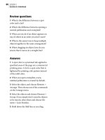
Architect’s letterhead
Review questions
1 What is the difference between a spot
color and a tint?
2 What’s the difference between opening a
normal publication and a template?
3 What can you do if an object appears on
top of others in an order you don’t want?
4 What is the easiest way to keep multiple
objects together in the same arrangement?
5 When dragging an object, how do you
ensure that it moves in a straight line?
Answers
1 A spot color is a premixed ink applied to
specified areas of the page on a commercial
printing press. A tint is a spot color that is
lightened by printing a dot pattern instead
of the solid color.
2 When you open a template, a new,
untitled publication is created by default.
3 Select the object, and choose Element >
Arrange. Then choose one of the commands
on the Arrange menu.
4 Select the objects and choose Element >
Group. If you simply don’t want the objects
to be moved, select them and choose Ele-
ment > Lock Position.
5 Hold down the Shift key as you drag.
Lesson 3
Project proposal
The project proposal you’ll create in this
lesson presents an architect’s plan for the
development of a community facility within
the town of Bella Coola, British Columbia.
This three-page, black-and-white publication
uses the same framework and design elements
on each page. So that you’ll only have to
create them once, you’ll build a master page
containing the
text, graphics, column guides,
and page-numbers that you want to appear
on every
page.
LESSON 3
82
Project proposal
In addition to assembling a master page, this
lesson introduces you to using styles to
apply character and paragraph formatting
attributes to paragraphs. More than ensur-
ing consistency in a publication, styles free
you from repeatedly selecting and applying
individual formatting attributes to each
paragraph in a publication. Although the
PageMaker application provides a collection
of styles (style sheet), you will create and
edit styles to build a style sheet specific to
this publication.
This lesson covers:
• Establishing a master page
• Adding tints to the Colors palette
• Using the Control palette to resize objects
proportionally and to move objects
• Specifying automatic page numbering
• Establishing a publication default stroke
style and weight
• Using page icons to turn pages
• Displaying and hiding master-page
elements
• Overriding the default leading method
• Autoflowing text
• Adjusting the tracking (the spacing
between words and letters)
• Varying the number of columns on
a page
• Overriding type and paragraph
specifications
• Creating, editing, and applying styles
• Creating a custom text wrap
It should take you approximately 2 hours to
complete this lesson.
Before you begin
All files and fonts needed for this lesson are
found on the Adobe PageMaker Classroom in
a Book CD-ROM in the folders 03Lesson
and Fonts, respectively.
Note: Windows users need to unlock the lesson
files before using them. For information, see
Copying the Classroom in a Book files on page
4.
Opening an existing document
Let’s take a look at the final version of the
proposal you will create in this lesson.
1 Before launching PageMaker, return all
settings to their defaults by deleting the
PageMaker 7.0 preferences file. See
“Restoring default settings” in Lesson 1.
2 In addition to the commonly used fonts
listed in the Getting Started chapter, make
sure the following fonts are installed: AGar-
amond, AGaramond Bold, AGaramond
Bold Italic, Birch, Myriad Bold, and Myriad
Roman.
Windows only: Because of the way Windows
handles fonts, AGaramond Semibold Italic
appears in the ATM Fonts list as AGaramond,
Bold Italic (notice the position of the comma),
while AGaramond Bold Italic appears as
AGaramond Bold, Italic. However, neither
AGaramond Bold Italic nor AGaramond
83
ADOBE PAGEMAKER 7.0
Classroom in a Book
Bold, Italic appear in font menus in Windows
applications. You must apply italic to AGara-
mond Bold to use AGaramond Bold Italic. You
must apply bold to Myriad Roman to use
Myriad Bold.
All fonts used in this publication are Adobe
Originals fonts. Birch is a particularly legible
condensed display typeface and is notable
for its angled serifs.
3 Launch PageMaker.
4 Choose File > Open, and double-click the
03Final.pmd file in the 03Lesson folder to
view the proposal you will create.
The full view of the first page displays a
variety of text and graphic elements, with a
single column of text positioned above two
columns of text. The page icons in the lower
left corner of the publication window indi-
cate this document consists of three pages.
5 If the publication window does not fill the
screen, click the Maximize button in the title
bar to expand the window.
6 Click the page 2 icon in the lower left
corner of the publication window to view
the second page.
To move forward one page, press the
Page Down key. To move backward one
page, press the Page Up key.
The left margin of the second page displays
the rotated display text, page number, and
graphics that appear on each page of this
document.
BELLA COOLA
The Bella Coola Development Study
merges community requirements for the
envisioned facility and the alternative
approaches to building on the Bella
Spectacular solar site: the southern face along
Grant Road will provide enough solar energy
for the entire three level structure.
Project
Plan
1
main. In addition, it has been envisioned that
jointly required facilities would be available for
all organizations to use on a shared basis, uti-
lizing movable walls for privacy.
In utilizing the Northern Pointe site, it is
initially assumed that the envisioned facilities
would be largely accommodated below
grade, and that above grade structures would
be intended to accommodate those func-
tions demanding particular visibility and iden-
tity, such as a community recreation center.
It is very possible that significant heating
and cooling economies would be achieved by
virtue of underground construction and the
application of appropriate solar collection
techniques. The southern face of proposed
structures along Grant Road offer optimum
orientation for collection of solar energy. Ad-
ditionally, natural illumination of below grade
spaces would significantly improve the quali-
ty of the indoor environment and has been
recognized as an important component of
the project.
AVAILABLE SPACE ANALYSIS
On the schematic site plan of the Northern
Pointe site, a total area of some 200 feet by
450 feet is indicated as the proposed maxi-
mum extent of below grade development. In
addition, we believe that a 345 feet by 475
feet area to the north of the community cen-
ter may be considered for future inclusion in
Northern Pointe development plans, although
it is not under consideration in this study.
Coola Northern Pointe site. Consultants’ re-
ports regarding structural considerations and
tree evaluation are included for their con-
tinued application to the problem. An effort
has been made to work with the full extent of
space requirements currently voiced by the
Western Division Management Center and the
Bella Coola Village Organization. Other organi-
zations were queried to form the basis of
judgment in determining the overall need. This
recognizes that as the program development
progresses, tenant requirements may change,
but the essential square footage and cubic
limitations for a below grade structure will re
Skylights, balconies, and sunken gardens
provide light to below grade levels.
Preservation of thirty-one
major trees identified in the
northeast corner of the site
would significantly reduce the
total space available for devel-
opment. It is recommended that
the soil should remain undisturbed
within 25 feet of the perimeter of the
trees’ root systems. Consequently, an area
of some 185 feet by 320 feet would be exclud-
ed from development plans in an effort to pre-
serve the grove of Douglas Fir trees.
Preliminary analysis of the site has indi-
cated that it would be feasible to construct
three below grade levels. However, structural
considerations of excavation and proximity to
adjoining buildings may be reviewed. With
these parameters in mind, it can be calculated
that, for below grade construction alone,
there is cubage available to accommodate
273,650 square feet of space in three levels.
This assumes that recommended measures
would be taken to preserve the Douglas Fir
trees, and utilized in the design.
The extent of above grade construction is
constrained by a desire to limit the maximum
height of new construction to about 25 feet
to 28 feet above grade, and to largely pre-
serve the present garden environment of the
site. It should be noted that extensive above
grade construction would impair efforts to
provide natural illumination for below grade
spaces. Automobile ramp access from Grant
Road to below grade parking will need to be
given further consideration as well.
LIGHT AND VIEW CONSIDERATIONS
There is little doubt that the facility envi-
sioned for the Northern Pointe site will largely
rely upon adequate introduction of natural
light and view to the underground levels to
achieve a comfortable and successful indoor
environment. This could be accomplished
through the use of sunken gardens which
would adjoin below grade working areas to
provide light as well as important visual ori-
entation and variety. It can be recognized that
sunken gardens or other light-searching ar-
chitectural elements will require substantial
space to be fully effective.
A recent study of such underground ar-
chitectural spaces notes that many of the
kinds of space with which we are dealing,
would, “because of the dominant modes of
activity within them, require relief by physical
or visual connection to adjacent high activity
areas or the external environment, or both.
Characteristic occupancy of such spaces
would by relatively secondary and routinized.
Characteristic examples of such spaces would
be conference centers, classrooms, and offic-
es” (superscript 1 here).
It is our judgment that the quantity and
quality of natural light and external views
deemed adequate for underground spaces in
the Northern Pointe Development cannot be
established with certainty, owing to the pre-
liminary nature of this study and the large
An open design: interior plan of lower level
conference room utilizes moving dividing
walls to create privacy amongst community.
Project
Plan
2
LESSON 3
84
Project proposal
7 Click the page 3 icon to view the third
page.
Again, the left margin displays the graphics
and rotated display text.
8 Click the page 1 icon to return to the first
page.
9 Choose View > Show Guides to display
the guides used to assemble this proposal.
Defining printing requirements
This project proposal was designed to be
printed on a 300 dpi or 600 dpi desktop laser
printing device. As mentioned in the first
lesson, you need to determine the maximum
printable area of the target printing device
before assembling a publication.
When printed on a 300 dpi or 600 dpi
desktop laser printing device, grayscale
photographic images scanned at a resolu-
tion of 100 dpi will meet the print quality
requirements of this publication. Grayscale
illustrations, however will print more clearly
if scanned at 300 dpi. However, to save disk
space, all the images in this project have
been scanned at 100 dpi.
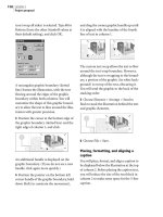
Assembling a master page
Every PageMaker publication contains at
least one body page and one master page.
While body pages contain the actual text and
graphics of the publication, master pages
contain repeating elements, such as margin
and column guides, page numbers, headers,
and footers. In PageMaker, the default mas-
ter page is called Document Master. You can
create and name additional master pages if
your publication contains more than one
page design. For example, in a book the table
of contents, chapter divider, first page of a
chapter, body of the chapter, and index all
may have separate master pages.
To produce a more cohesive design for this
multipage publication, you will establish a
master page that will contain a variety of
design elements, such as guides, repeating
text, page numbering, and graphic elements
that will be common to all its pages.
Creating a new publication
To create a master page, create a new or open
an existing publication, and then display the
master page itself.
1 Choose File > New. Make sure Letter is
selected for Page Size. Click Double-sided to
deselect it. To set the margin guides, type 2.5
for Left, .75 for Right, .75 for Top, and .75
for Bottom. Choose 600 dpi for Target
number of unresolved controlling factors. Yet
it is evident that space will be required and
must be set aside for natural light.
Accordingly, we believe that space for
natural light and view must be initially allocat-
ed on the basis of approximate judgment in
lieu of more fixed guidelines. To this end, 15%
of the total gross floor area, or some 42,500
square feet, is allocated for natural light and
view throughout the underground areas. We
expect that during further development of
this project, new information may suggest
some adjustment of this allocation.
CONCLUSIONS
Preceding analysis has delineated the clear
limitations of space available for development
below grade on the Northern Pointe site. At
this juncture it would appear reasonable to ex-
pect that 166,350 square feet of space could
be accommodated below grade, easily accom-
modating the three-level design. Further ex-
pansion below grade to the north of the Grant
Community Center may constitute valuable
space available for further development,
although it has not been studied herein or in-
cluded in available space estimates.
Although the constraints on above grade
construction do not directly translate into
clear limitations of available space, examina-
tion of a range of options has led to a recom-
mendation to accommodate 32,000 square
feet of space in two buildings above grade. In
the time frame of Northern Pointe develop-
ment it is felt that the Douglas Fir trees alone
would merit preservation during construction,
although replacement planting of a number
of major trees is envisioned to follow con-
struction. The current space planning figures
reflect these assumptions.
The resulting total 253,850 gross square
feet of space estimated to be available for de-
velopment exceeds the current requirements
of 250,000 square feet by a moderate amount.
We would not necessarily suggest any further
increase in the program size to more closely
match the space available for development.
There is considerable leeway for adjust-
ment of the siting and configuration of the
above grade buildings under consideration.
At this level of investigation, only schematic
studies of this question can be undertaken. A
number of schemes of massing options have
been studied, and the strongest two have
been selected for illustration to suggest alter-
nate ways to approach this unique problem.At
this stage, it is suggested that the recom-
mendations in this study be equally reviewed.
Above is a detail from the proposed expansion plan to north of the Grant Community Center.
Project
Plan
3
85
ADOBE PAGEMAKER 7.0
Classroom in a Book
Output Resolution and choose (Windows
only) HP LaserJet 5Si for Compose to
Printer. Then click OK.
Note: If you do not have the required printer,
you can still create the project as directed and
then
print it on your own printer by
selecting your printer and its PPD (if it is a
PostScript printer) in the Print dialog box
when it is time to print.
Yo u can also use the
Export Adobe PDF command to create an
Adobe PDF version of the project rather than
a printed copy, as described in Creating an
Adobe PDF version of the flyer on page 41.
The publication window displays the unti-
tled publication with the specified page
dimensions and margin guides.
2 Choose File > Save As, and type
03Work.pmd for the file name, open the
03Lesson folder (if not already open), and
click Save.
The page 1 icon is highlighted, indicating
page 1 is selected. To import, create, and
modify text and graphic elements on a mas-
ter page, you must select the master page.
3 Click the R master-page icon in the lower
left corner of the publication window.
LESSON 3
86
Project proposal
PageMaker displays the master page, and
highlights the R icon. The page still displays
the margin guides you specified in the Doc-
ument Setup dialog box.
Note: A single-sided publication has only one
master-page icon. In a double-sided publica-
tion, you would see master-page icons L and R
(for the left and right master pages).
Creating column guides
With the margins already defined using the
Document Setup dialog box, you are ready
to specify the column guides. Even though it
is possible to vary column guides from page
to page, placing column guides on master
pages provides a consistent look throughout
a publication. In addition, specifying col-
umn guides on the master page saves you the
effort of specifying column guides on indi-
vidual pages.
1 Choose Layout > Column Guides. Type 2
for Number of columns, and click OK.
PageMaker automatically creates columns of
equal width, filling the entire image area
between margin guides. Any column guides
or ruler guides you create on a master page
are automatically displayed on publication
pages.
2 Choose File > Save.
Adding tints to the Colors palette
In previous lessons, you used the Colors
palette to apply tints (lightened colors) to
text and graphic objects. In this lesson, you
will add two tints of black to the Colors pal-
ette, providing a shortcut to applying the
same tint to multiple objects.
1 Choose Utilities > Define Colors, and
click the New button.
2 In the Color Options dialog box, type
20% Gray for Name, choose Tint for Type,
choose Black for Base Color, type 20 for
Tint, and click OK to close each dialog box.
You need to define another color, but this
time you’ll use the Colors palette.
87
ADOBE PAGEMAKER 7.0
Classroom in a Book
3 In the Colors palette, either click the new
color button at the bottom of the palette or
choose New Color from the palette menu.
4 In the Color Options dialog box, type
10% Gray for Name, choose Tint for Type,
choose Black for Base Color, type 10 for
Tint, and click OK.
The Colors palette displays the tints 10%
Gray and 20% Gray in its list of colors and
adds a % sign to the right of each tint name.
5 Choose File > Save.
Using the Control palette to resize an
object proportionally
After drawing a circle, you will use the Con-
trol palette to resize and position it. This cir-
cle will serve to frame the page numbers.
1 Select the zoom tool (), and magnify
the view of the upper left corner of the page.
2 Select the ellipse tool (), hold down
Shift (to constrain the ellipse to a circle), and
drag to draw a circle of any diameter in the
upper left corner of the page.
3 In the Control palette, click the Scaling
button to toggle it to proportional scaling
() so that the circle stays round. Then
type .85 for W, and press Enter or Return.
By default, the Scaling button is set to non-
proportional scaling, letting you scale an
object’s height and width independently.
When set to proportional scaling, you can
enter a single value and PageMaker resizes
the object evenly in both directions.
4 In the Colors palette, click the Both but-
ton
(), and select 20% Gray to apply the
20% tint of black to the stroke and fill of the
circle.
5 Choose File > Save.
Specifying automatic page numbering
To automatically number all pages in this
publication, you will place a page-number
marker on the master page.
Note: With PageMaker, you can number the
pages of a multiple-publication document
consecutively from the first publication
through the last, restart the page numbering
in each publication, or combine the two
Palette men
u
New color button
Proportional-scaling button
Non-proportional Proportional
LESSON 3
88
Project proposal
methods. You can also tell PageMaker to begin
each successive publication on the next odd or
even page number.
1 Select the text tool (), and drag to define
a text block over the gray circle that is wider
and taller than the gray circle (exact dimen-
sions are not important).
Yo u’ll set the text attributes before you type
the page-number marker.
2 In the Control palette, choose AGara-
mond Bold for Font. Type 50 for Size
()
and 70 for Leading
(). Click the Paragraph
view button
(), and click the Center-align
button
().
3 Hold down Ctrl and Alt (Windows) or
Command and Option (Macintosh), and
press p.
The center-aligned page-number marker
RM (right master) is displayed on the gray
circle, indicating where page numbers will
appear.
Note: If your publication had facing pages,
you would add a page-number marker on
both the right and left master pages.
4 Select the pointer tool, and click the page-
number marker. Then hold down Shift
together with Ctrl (Windows) or Command
(Macintosh) and click again to select the
circle. (Holding down Ctrl or Command lets
you select an object underneath an object.)
5 With both objects selected, choose Ele-
ment > Align Objects (Windows) or Ele-
ment > Align (Macintosh). Click both the
vertical and horizontal Center-Align but-
tons, and click OK.
6 With both objects still selected, select the
center reference point in the Control palette
Proxy icon. Type 1 for X and .75 for Y, and
press Enter or Return to align the center of
the two objects with the specified coordinate
position.
Remember: Unless otherwise stated, the
reference point in the Control palette Proxy
icon should be a square point, not an arrow.
7 Select the text tool, and double-click the
page-number marker to select it.
8 In the Colors palette, click [Paper] to
apply the paper color to the page number.
9 Choose File > Save.
RM
89
ADOBE PAGEMAKER 7.0
Classroom in a Book
Establishing a publication default
stroke style and weight
Before drawing lines (to be printed) over
ruler guides and column guides (which
don’t print), you will set a default stroke
style and weight for the publication. If you
know ahead of time that several elements in
your publication will share certain charac-
teristics (such as stroke style and weight),
selecting default settings can save you time.
For example, once you set a stroke style and
weight, PageMaker will use those default set-
tings each time you draw a line, ellipse, rect-
angle, polygon, or frame.
1 Click the pointer tool in the toolbox to
deselect all objects.
2 Choose Element > Stroke > .5-pt line to
establish a publication default.
3 Choose View > Send Guides to Back.
4 From the horizontal ruler, drag to create a
horizontal ruler guide at approximately 2.16
inches.
Note: Use the Control palette to help you posi-
tion ruler guides. It displays the pointer loca-
tion as you drag.)
5 From the vertical ruler, drag to create a
vertical ruler guide at 1 inch.
The first line segment you will draw is a
vertical line.
6 Select the constrained-line tool (), posi-
tion the crosshair on the intersection of the
bottom edge of the gray circle and the 1-inch
vertical ruler guide, and drag down to the
2.16-inch horizontal ruler guide to draw
a line.
Rather than creating a new vertical ruler
guide, you will reposition an existing guide
that is no longer needed.
7 Select the pointer tool, and position the
pointer over the existing 1-inch vertical
ruler guide. Hold down the mouse button
until the pointer changes to a double arrow,
drag it until it is aligned with the 2.25-inch
mark on the horizontal ruler, and release the
mouse button to reposition the guide.
The second line segment you will draw is a
horizontal line.
8 Select the constrained-line tool, position
the crosshair at the ending point of the line
you just drew, and drag right to the intersec-
tion of the 2.16-inch horizontal ruler guide
and the 2.25-inch vertical ruler guide to
draw a second line.
9 Choose View > Fit in Window to view the
entire master page.
RM
RM
LESSON 3
90
Project proposal
10 From the horizontal ruler, drag to create
a horizontal ruler guide aligned with the
bottom margin guide at 10.25 inches.
The 10.25-inch horizontal ruler guide
extends beyond the bounds of the bottom
margin guide, facilitating precise alignment
across the entire page.
The final line segment you will draw is a ver-
tical line.
11 With the constrained-line tool still
selected, position the crosshair at the right
ending point of the second line you just
drew, and drag down to the 10.25-inch hor-
izontal ruler guide to draw a third line.
12 Choose File > Save.
Creating the rotated display text
You will create, rotate, and align the display
text that is positioned in the left margin of
the master page.
1 Select the text tool (), drag to define a
text block that spans the width of the image
area (between the left and right margin
guides).
Before typing the text, you will use the
Control palette to format the text.
2 In the Control palette, press the Charac-
ter-view button. Then, choose AGaramond
(Regular) for Font, type 130 for Size
(),
and click the Apply button
().
3 Type Project.
4 With the text tool selected, double-click
Project to select it. In the Colors palette,
click 10% Gray to apply the 10% tint of
black to the text.
RM
RM
91
ADOBE PAGEMAKER 7.0
Classroom in a Book
5 Select the pointer tool, and click the text
to select it as a text block. In the Control
palette, make sure the center point of the
Proxy icon is selected, type 90 for Rotation
(), and click the Apply button ().
The text is rotated on the center point of the
text block.
6 From the horizontal ruler, drag to create a
horizontal ruler guide at approximately 9.12
inches.
7 From the vertical ruler, drag to create a
vertical ruler guide at approximately 1.57
inches.
8 Choose View > Snap to Guides to deselect
(uncheck) the option.
9 With the pointer tool still selected, click
the text Project to select it as a text block,
and drag it until its baseline is aligned with
the 1.57-inch vertical ruler guide, with the
bottom edge of the letter P aligned with the
9.12-inch horizontal ruler guide.
Remember: If you drag immediately after
pressing the mouse button, you see the
bounding box of the text block. If you pause
before you drag, you see the characters in the
text block as you drag, making it easier to
align the baseline to a ruler guide or to align
characters to each other.
10 Choose File > Save.
Replacing selected text
You can save a bit of time if you copy and
paste the word Project to create a new text
block, and then replace Project with the
word Plan. The new word will already be
rotated and have the correct font applied.
1 With the pointer tool still selected, click
the word Project to select it as a text block,
and choose Edit > Copy, and then choose
Edit > Paste.
RM
Proje
ct
Project
RM
LESSON 3
92
Project proposal
The pasted text block is rotated like the cop-
ied text block, and the text is formatted like
the copied text.
2 Select the text tool (), double-click the
pasted text to select it, and type Plan to
replace the pasted text.
3 Double-click the word Plan to select it,
and in the Colors palette click 20% Gray.
This design calls for the word Plan to use a
smaller font size.
4 With Plan still selected, in the Control
palette type 100 for Size
(), and click the
Apply button.
5 Select the pointer tool, and drag the exist-
ing 2.25-inch vertical ruler guide to approx-
imately 2.15 inches.
6 With the pointer tool still selected, click
the word Plan to select it as a text block, and
drag it until its baseline is aligned with the
2.15-inch vertical ruler guide, with the stem
of the letter P in the word Plan aligned with
the stem of the letter t in the word Project as
shown below.
7 With the pointer tool selected, drag the
top right handle to conform to the word
Plan.
Plan overlaps Project, and the master page
is complete.
8 Choose Edit > Select All and then
Element > Lock Position to prevent acciden-
tally modifying the master-page elements.
9 Choose File > Save.
Displaying and hiding master-page
elements
You can display master-page elements on a
page-by-page basis, making it possible to
create a publication that makes use of
master-page elements on certain pages.
Project
RM
Plan
RM
Project
Plan
93
ADOBE PAGEMAKER 7.0
Classroom in a Book
1 Click the page 1 icon in the lower left
corner of the publication window to view
the first page.
Since master-page elements are auto-
matically displayed on each page of the
publication, the first page of the publication
is displayed along with all master-page
elements. The master page elements are at
the bottom of the stacking order on the page
and cannot be moved.
Notice that this page displays an actual page
number instead of the page number marker.
2 Choose Edit > Select All, and notice how
none of the master-page elements are
selected.
Since the first page is displayed, it is not
possible to select text and graphic elements
on the master page.
You can easily hide master-page elements
on a particular page in your publication,
provided it is the current page.
3 With the first page still displayed, choose
View > Display Master Items to deselect the
option.
The text and graphic elements that you
created disappear, and the nonprinting
guides (margin, column, and ruler) are not
affected. If you were to print this page, none
of the master-page elements would be
printed.
4 Choose View > Display Master Items to
again display the master page items.
The first page of the publication is displayed,
along with all master-page elements.
Assembling the first page
To assemble the first of three pages of the
proposal, you will begin by creating and
modifying text. Once the text is formatted,
you will create new styles and edit existing
styles that you will use throughout the rest
of this publication.
Creating the title
After establishing the character and
paragraph specifications for the title (Bella
Coola) that spans the top of the first page of
the proposal, you will type the text and
apply a 75% tint of black using the Colors
palette.
1 Select the text tool (), and drag to define
a text block that spans the width of the two
columns (exact height is not important).
Project
Plan
1
LESSON 3
94
Project proposal
2 In the Control palette, choose Birch for
Font, type 100 for Size
(), and click the All
Caps button
().
Note: By default, PageMaker automatically
sets the leading to 120% of the font size (as
indicated in the Control palette).
3 Type bella coola.
Because you had selected the All Caps
button in the Control palette, the text is
displayed in uppercase letters.
4 With the text tool still selected, drag to
select the letter B in the word BELLA, and in
the Control palette type 120 for Size, and
click the Apply button.
Note: If different leading amounts occur
within a single line, PageMaker uses the
largest leading amount for the entire line.
Since leading is a character attribute, you can
apply more than one leading amount within
the same paragraph.
5 Drag to select the letter C in the word
COOLA, and, in the Control palette, type
120 for Size, and click the Apply button.
6 With the text tool still selected, triple-click
the title text to select it.
7 In the Control palette, click the Para-
graph-view button
(), and then click the
Force-justify button
() to force the title
text to spread across the width of the text
block (which spans the two columns).
8 With the text still selected, make sure
[Black] is selected in the Colors palette, and
choose 75% for Tint to apply a 75% tint of
black.
BELLA COOLA
Project
Plan
1
BELLA COOLA
Project
Plan
1
95
ADOBE PAGEMAKER 7.0
Classroom in a Book
To make the text easier to work with, you
will change the leading method used for the
title. The leading method controls where
text sits in the slug. (As mentioned in Lesson
1, a slug is the vertical space used by each
line of type.)
PageMaker lets you choose three different
leading methods: proportional (the default
method), top of caps, and baseline. Propor-
tional and baseline leading are the most
common methods.
A. Proportional leading B. Top of Caps leading
C. Baseline leading
The proportional leading method (the
method currently applied to the title) aligns
the baseline of the text one-third of the slug
height above the bottom of the slug. The
baseline leading method, on the other hand,
aligns the baseline of the text with the bot-
tom of the leading slug.
When using baseline leading, the baseline of
the last line of text in a text block aligns with
the bottom of the text block. Because you’ll
be placing text underneath this title, it will
be easier to work with other text blocks if
the bottom of the title text block is not in
the way.
9 With the text still selected, notice where
the text sits in the highlighted leading slug.
Choose Type > Paragraph.
10 In the Paragraph Specifications dialog
box, click the Spacing button.
The Spacing Attributes dialog box (Win-
dows) and Paragraph Spacing Attributes
dialog box (Mac OS) lets you to control the
amount of space inserted between letters
and words, the leading method, and the per-
centage of autoleading. In this example you
will use the Spacing Attributes dialog box to
override the proportional (default) leading
method with the baseline leading method.
11 In the Spacing Attributes dialog box
(Windows) or Paragraph Spacing Attributes
dialog box (Mac OS), select Baseline for
Leading Method. Hold down Shift (Win-
dows) or Option (Macintosh), and click OK
to close all the dialog boxes at once.
Bella Coola
Bella Coola
Bella Coola
ABC
LESSON 3
96
Project proposal
Notice that the slug has shifted in the title
so that the baseline touches the bottom of
the slug.
12 Select the pointer tool, click the title text
to select it as a text block, hold down Shift
(to constrain the movement to 90º), and
drag the text block to align the top edge of
the smaller letters with the top
margin guide.
The 120-point letters overlap the top
margin.
13 Choose File > Save.
Placing text using the Autoflow
command
Use the Autoflow command when you have
a lot of text to place. Flowing text automati-
cally means PageMaker will create new pages
until all text is placed, eliminating the need
for you to add individual pages.
1 Choose File > Place, and double-click the
03TextA.doc file in the 03Lesson folder.
2 Choose Layout > Autoflow.
The pointer changes to an automatic
text-flow icon.
PageMaker has three text flow modes, each
represented by a different text-flow icon:
Manual flow Flows one column or text
block at a time.
Automatic flow Flows text column to
column until the entire story is placed,
adding pages if needed.
Semiautomatic flow Flows text one
column or text block at a time, ending
with the loaded text icon if more text
remains to be placed.
Whenever you have a loaded text
icon, you can switch temporarily between
manual and automatic text flow by press-
ing Ctrl (Windows) or Command (Mac-
intosh). To switch temporarily to semiau-
tomatic flow, hold down Shift when the
loaded text icon is displayed.
BELLA COOLA
Project
Plan
1
97
ADOBE PAGEMAKER 7.0
Classroom in a Book
3 Making sure the automatic text-flow icon
does not overlap the margin guides or col-
umn guides, click in column 1 below the title
text.
The last lines of text in the story are
displayed on page 3 of your publication,
indicating PageMaker has automatically
inserted two pages.
4 With the pointer tool selected, click the
text in column 1 to select it as a text block.
The plus sign in the top windowshade han-
dle indicates that text from the same story is
contained in another text block, and the
empty bottom windowshade handle indi-
cates the end of the story.
5 Click the page 2 icon to view the second
page of the publication.
6 With the pointer tool selected, click the
text in either column to select it as a text
block.
Note: Depending upon your monitor size and
the zoom level, the text in both columns may
be grayed-out.
The top and bottom windowshade handles
of the selected text block display plus signs
(). As just mentioned, a plus sign in the
windowshade handle indicates that text
from the same story is contained in another
text block.
Plus sign
In previous lessons you placed and created
stories that were contained in a single text
block. Since the story in this lesson is con-
tained in five text blocks, the text in this
publication is threaded (through multiple
text blocks).
BELLA COOLA
Project
Plan
1
Project
Plan
2
these parameters in mind, it can be
calculated that, for below grade
construction alone, there is cubage
available to accommodate 273,650
square feet of space in three levels.
This assumes that recommended
measures would be taken to preserve
the Douglas Fir trees, and utilized in
the design.
The extent of above grade construc-
tion is constrained by a desire to limit
the maximum height of new con-
struction to about 25 feet to 28 feet
above grade, and to largely preserve
the present garden environment of the
site. It should be noted that extensive
above grade construction would
impair efforts to provide natural
illumination for below grade spaces.
Automobile ramp access from Grant
Road to below grade parking will
need to be given further consideration
as well.
Light and View Considerations
There is little doubt that the facility
envisioned for the Northern Pointe
site will largely rely upon adequate
introduction of natural light and view
to the underground levels to achieve a
comfortable and successful indoor
environment. This could be accom-
plished through the use of sunken
gardens which would adjoin below
grade working areas to provide light
as well as important visual orienta-
tion and variety. It can be recognized
that sunken gardens or other light-
searching architectural elements will
require substantial space to be fully
effective.
A recent study of such underground
architectural spaces notes that many
of the kinds of space with which we
are dealing, would, “because of the
dominant modes of activity within
them, require relief by physical or
visual connection to adjacent high
activity areas or the external environ-
ment, or both. Characteristic occu-
pancy of such spaces would by
relatively secondary and routinized.
Characteristic examples of such
spaces would be conference centers,
classrooms, and offices” (superscript
1 here).
It is our judgment that the quantity
and quality of natural light and
external views deemed adequate for
underground spaces in the Northern
Pointe Development cannot be
established with certainty, owing to
the preliminary nature of this study
and the large number of unresolved
controlling factors. Yet it is evident
that space will be required and must
be set aside for natural light.
Accordingly, we believe that space
for natural light and view must be
initially allocated on the basis of
approximate judgment in lieu of
more fixed guidelines. To this end,
15% of the total gross floor area, or
some 42,500 square feet, is allocated
for natural light and view throughout
the underground areas. We expect
that during further development of
this project, new information may
suggest some adjustment of this
allocation.
Conclusions
Preceding analysis has delineated the
clear limitations of space available
for development below grade on the
Northern Pointe site. At this juncture
it would appear reasonable to expect
that 166,350 square feet of space
could be accommodated below grade,
easily accommodating the three-level
design. Further expansion below
grade to the north of the Grant Com-
munity Center may constitute valu-
able space available for further
LESSON 3
98
Project proposal
7 Click the page 1 icon to view the first page
of the publication.
8 With the pointer tool selected, click the
text in column 1 to select it as a text block.
The first line of text in column 1 is posi-
tioned where you clicked to place the text,
with the empty top windowshade handle
() indicating the beginning of a story.
Do not worry if the tops of the two text
blocks are not aligned at this point. You will
be resizing these later to make room for an
introductory paragraph that spans both
columns.
Note: If no text had been positioned in the top
portion of column 2, the entire right column
would have been filled with text.
9 Choose File > Save.
Adjusting the tracking
After formatting the text, you will use the
Expert Tracking command to adjust the
spacing between letters and words (track-
ing) in the proposal text. This command is
useful for darkening or lightening a page—
type with tight tracking darkens a page, and
type with loose tracking lightens a page. You
can also use Expert Tracking to adjust the
spacing of selected lines of very large or very
small type (headlines and captions), or to
make text fit in a defined space on a page.
1 Select the text tool (), click the proposal
text to establish an insertion point, and
choose Edit > Select All to select the entire
threaded story.
Note: Once the entire story is formatted, you
can apply specific styles to a few specific para-
graphs (such as headlines, subheads, etc.) to
override the original formatting, saving you
the effort of formatting all paragraphs indi-
vidually.
2 In the Control palette, click the Character-
view button. Choose Myriad Roman for
Font, type 8.7 for Size
() and 13 for Lead-
ing
(), and click the Apply button ().
3 With the text still selected, click the Para-
graph-view button
() in the Control pal-
ette. Then type .25 for First-line Indent
(), and click the Justify button ().
BELLA COOLA
The Bella Coola Development Study
merges community requirements for
the envisioned facility and the alter-
native approaches to building on the
Bella Coola Northern Pointe site.
Consultants’ reports regarding struc-
tural considerations and tree evalua-
tion are included for their continued
application to the problem. An effort
has been made to work with the full
extent of space requirements cur-
rently voiced by the Western Division
Management Center and the Bella
Coola Village Organization. Other
organizations were queried to form
the basis of judgment in determining
the overall need. This recognizes that
as the program development
progresses, tenant requirements may
change, but the essential square
footage and cubic limitations for a
below grade structure will remain. In
addition, it has been envisioned that
jointly required facilities would be
available for all organizations to use
on a shared basis, utilizing movable
walls for privacy.
In utilizing the Northern Pointe site,
it is initially assumed that the envi-
sioned facilities would be largely
accommodated below grade, and that
above grade structures would be
intended to accommodate those
functions demanding particular
visibility and identity, such as a
community recreation center.
It is very possible that significant
heating and cooling economies would
be achieved by virtue of underground
construction and the application of
appropriate solar collection tech-
niques. The southern face of pro-
posed structures along Grant Road
offer optimum orientation for collec-
tion of solar energy. Additionally,
natural illumination of below grade
spaces would significantly improve
the quality of the indoor environment
and has been recognized as an impor-
tant component of the project.
Available Space Analysis
On the schematic site plan of the
Northern Pointe site, a total area of
some 200 feet by 450 feet is indicat-
ed as the proposed maximum extent
of below grade development. In addi-
tion, we believe that a 345 feet by
475 feet area to the north of the
community center may be considered
for future inclusion in Northern
Pointe development plans, although it
is not under consideration in this
study.
Preservation of thirty-one major trees
identified in the northeast corner of
the site would significantly reduce the
total space available for development.
It is recommended that the soil
should remain undisturbed within 25
feet of the perimeter of the trees’ root
systems. Consequently, an area of
some 185 feet by 320 feet would be
excluded from development plans in
effort to preserve the grove of
Douglas Fir trees.
Preliminary analysis of the site has
indicated that it would be feasible to
construct three below grade levels.
However, structural considerations of
excavation and proximity to adjoin-
ing buildings may be reviewed. With
Project
Plan
1
99
ADOBE PAGEMAKER 7.0
Classroom in a Book
The first line of each paragraph is indented,
with the left and right edges of the text
aligned with the edges of the text block.
Now that the text is formatted, you will use
the Expert Tracking command to adjust the
spacing between letters and words (track-
ing) in the proposal text.
4 Hold down Ctrl (Windows) or Command
(Macintosh) together with the spacebar, and
drag diagonally across the text in column 1
to enclose half the text block.
In this magnified view, notice how the spac-
ing between letters and words in the pro-
posal text is fairly tight.
5 With the entire story still selected, choose
Type > Expert Tracking > Very Loose.
The Expert Tracking menu displays six
tracking options. The default tracking
option No Track means no tracking has
been applied to the text.
Because Very Loose tracking increases letter
spacing for this point size (of this typeface),
the loosened tracking makes the page appear
lighter.
Note: It is also possible to select a tracking
option from the Tracking pop-up menu in the
character view of the Control palette.
6 Choose File > Save.
Varying the number of columns
on a page
You can have a different number of columns
on different parts of a single page. In this
example, you will create a single column of
text below the title text, above the two exist-
ing columns of text.
You will begin by reducing the size of the
text blocks in the left and right columns to
make room for a text block that spans the
image area (between the left and right
margins).
BELLA COOLA
The Bella Coola Development Study
merges community requirements for the en-
visioned facility and the alternative ap-
proaches to building on the Bella Coola North-
ern Pointe site. Consultants’ reports regarding
structural considerations and tree evaluation
are included for their continued application to
the problem. An effort has been made to work
with the full extent of space requirements cur-
rently voiced by the Western Division Manage-
ment Center and the Bella Coola Village Orga-
nization. Other organizations were queried to
form the basis of judgment in determining the
overall need. This recognizes that as the pro-
gram development progresses, tenant require-
ments may change, but the essential square
footage and cubic limitations for a below
grade structure will remain. In addition, it has
been envisioned that jointly required facilities
would be available for all organizations to use
on a shared basis, utilizing movable walls for
privacy.
In utilizing the Northern Pointe site, it is
initially assumed that the envisioned facilities
would be largely accommodated below grade,
and that above grade structures would be in-
tended to accommodate those functions de-
manding particular visibility and identity, such
as a community recreation center.
It is very possible that significant heating
and cooling economies would be achieved by
virtue of underground construction and the
application of appropriate solar collection
techniques. The southern face of proposed
structures along Grant Road offer optimum
orientation for collection of solar energy. Ad-
ditionally, natural illumination of below grade
spaces would significantly improve the quali-
ty of the indoor environment and has been
recognized as an important component of the
project.
Available Space Analysis
On the schematic site plan of the North-
ern Pointe site, a total area of some 200 feet
by 450 feet is indicated as the proposed max-
imum extent of below grade development. In
addition, we believe that a 345 feet by 475 feet
area to the north of the community center may
be considered for future inclusion in Northern
Pointe development plans, although it is not
under consideration in this study.
Preservation of thirty-one major trees
identified in the northeast corner of the site
would significantly reduce the total space
available for development. It is recommended
that the soil should remain undisturbed within
25 feet of the perimeter of the trees’ root sys-
tems. Consequently, an area of some 185 feet
by 320 feet would be excluded from develop-
ment plans in an effort to preserve the grove
of Douglas Fir trees.
Preliminary analysis of the site has indi-
cated that it would be feasible to construct
three below grade levels. However, structural
considerations of excavation and proximity to
adjoining buildings may be reviewed. With
these parameters in mind, it can be calculated
that, for below grade construction alone, there
is cubage available to accommodate 273,650
square feet of space in three levels. This as-
sumes that recommended measures would be
taken to preserve the Douglas Fir trees, and
utilized in the design.
The extent of above grade construction is
constrained by a desire to limit the maximum
height of new construction to about 25 feet
to 28 feet above grade, and to largely preserve
the present garden environment of the site. It
should be noted that extensive above grade
construction would impair efforts to provide
natural illumination for below grade spaces.
Automobile ramp access from Grant Road to
below grade parking will need to be given fur-
ther consideration as well.
Light and View Considerations
There is little doubt that the facility envi-
sioned for the Northern Pointe site will largely
rely upon adequet introduction of natural
Project
Plan
1
LESSON 3
100
Project proposal
1 Scroll to view the middle portion of
the page.
2 From the horizontal ruler, drag to create a
horizontal ruler guide at approximately
4.17-inches. (Use the Control palette to ver-
ify its location as you drag.)
You will drag the top of the text blocks in the
two columns down to this horizontal ruler
guide. To help you align the text block, you’ll
first turn the Snap to Guides option back on.
3 Choose View > Snap to Guides to select
(check) the option.
4 Select the pointer tool, click the text in
column 2 to select it as a text block, and drag
the top windowshade handle down until it
snaps to the horizontal ruler guide you just
created.
5 With the pointer tool still selected, click
the text in column 1 to select it as a text
block, and drag the top windowshade han-
dle until it snaps to the ruler guide.
PageMaker automatically flows the text
when you resize the text blocks, displaying
the first line of text in the threaded story at
the top of the first text block.
6 If the baseline of the last line of text in col-
umn 2 is not aligned with the bottom mar-
gin guide, select the text block and drag the
windowshade handle to expose one more
line of text. (You can leave column 1 as is;
you’ll be adding a photograph and caption
to it.)
With the size of the text blocks reduced, you
have space to create a single column of text
below the title text.
BELLA COOLA
Project
Plan
1
The Bella Coola Development Study
merges community requirements for the en-
visioned facility and the alternative ap-
proaches to building on the Bella Coola North-
ern Pointe site. Consultants’ reports regarding
structural considerations and tree evaluation
are included for their continued application to
the problem. An effort has been made to work
with the full extent of space requirements cur-
rently voiced by the Western Division Manage-
ment Center and the Bella Coola Village Orga-
nization. Other organizations were queried to
form the basis of judgment in determining the
overall need. This recognizes that as the pro-
gram development progresses, tenant require-
ments may change, but the essential square
footage and cubic limitations for a below
grade structure will remain. In addition, it has
been envisioned that jointly required facilities
would be available for all organizations to use
on a shared basis, utilizing movable walls for
privacy.
In utilizing the Northern Pointe site, it is
initially assumed that the envisioned facilities
would be largely accommodated below grade,
and that above grade structures would be in-
tended to accommodate those functions de-
manding particular visibility and identity, such
as a community recreation center.
It is very possible that significant heating
and cooling economies would be achieved by
virtue of underground construction and the
application of appropriate solar collection
techniques. The southern face of proposed
structures along Grant Road offer optimum
orientation for collection of solar energy. Ad-
ditionally, natural illumination of below grade
spaces would significantly improve the quali-
ty of the indoor environment and has been
recognized as an important component of the
project.
Available Space Analysis
On the schematic site plan of the North-
ern Pointe site, a total area of some 200 feet
by 450 feet is indicated as the proposed max-
imum extent of below grade development. In
addition, we believe that a 345 feet by 475 feet
area to the north of the community center may
be considered for future inclusion in Northern
Pointe development plans, although it is not
under consideration in this study.
Preservation of thirty-one major trees
identified in the northeast corner of the site
would significantly reduce the total space
available for development. It is recommended
that the soil should remain undisturbed within
25 feet of the perimeter of the trees’ root sys-
tems. Consequently, an area of some 185 feet
by 320 feet would be excluded from develop-
ment plans in an effort to preserve the grove
of Douglas Fir trees.
Preliminary analysis of the site has indi-
cated that it would be feasible to construct
three below grade levels. However, structural
considerations of excavation and proximity to
adjoining buildings may be reviewed. With
these parameters in mind, it can be calculated
that, for below grade construction alone, there
is cubage available to accommodate 273,650
square feet of space in three levels. This as-
sumes that recommended measures would be
taken to preserve the Douglas Fir trees, and
utilized in the design.
The extent of above grade construction is
constrained by a desire to limit the maximum
height of new construction to about 25 feet
BELLA COOLA
Project
Plan
1
The Bella Coola Development Study
merges community requirements for the en-
visioned facility and the alternative ap-
proaches to building on the Bella Coola North-
ern Pointe site. Consultants’ reports regarding
structural considerations and tree evaluation
are included for their continued application to
the problem. An effort has been made to work
with the full extent of space requirements cur-
rently voiced by the Western Division Manage-
ment Center and the Bella Coola Village Orga-
nization. Other organizations were queried to
form the basis of judgment in determining the
overall need. This recognizes that as the pro-
gram development progresses, tenant require-
ments may change, but the essential square
footage and cubic limitations for a below
grade structure will remain. In addition, it has
been envisioned that jointly required facilities
would be available for all organizations to use
on a shared basis, utilizing movable walls for
privacy.
In utilizing the Northern Pointe site, it is
initially assumed that the envisioned facilities
would be largely accommodated below grade,
and that above grade structures would be in-
tended to accommodate those functions de-
manding particular visibility and identity, such
as a community recreation center.
It is very possible that significant heating
and cooling economies would be achieved by
virtue of underground construction and the
application of appropriate solar collection
techniques. The southern face of proposed
structures along Grant Road offer optimum
orientation for collection of solar energy. Ad-
ditionally, natural illumination of below grade
spaces would significantly improve the quali-
ty of the indoor environment and has been
recognized as an important component of the
project.
Available Space Analysis
On the schematic site plan of the North-
ern Pointe site, a total area of some 200 feet
by 450 feet is indicated as the proposed max-
imum extent of below grade development. In
addition, we believe that a 345 feet by 475 feet
area to the north of the community center may
be considered for future inclusion in Northern
Pointe development plans, although it is not
under consideration in this study.
Preservation of thirty-one major trees
identified in the northeast corner of the site
would significantly reduce the total space
available for development. It is recommended
that the soil should remain undisturbed within
25 feet of the perimeter of the trees’ root sys-
tems. Consequently, an area of some 185 feet
by 320 feet would be excluded from develop-
ment plans in an effort to preserve the grove
of Douglas Fir trees.
Preliminary analysis of the site has indi-
cated that it would be feasible to construct
three below grade levels. However, structural
considerations of excavation and proximity to
101
ADOBE PAGEMAKER 7.0
Classroom in a Book
7 Select the text tool (), drag to select the
first three and a half lines in column 1 (up to
and including the word Bella), and choose
Edit > Cut.
8 Position the insertion point at the begin-
ning of the remaining text in column 1
(before the word Coola), and if necessary
press the Backspace key to delete the letter
space.
9 With the text tool selected, drag to define
a text block above the text in the left and
right columns, spanning the width of the
two columns (exact height is not impor-
tant), and choose Edit > Paste.
No longer part of the threaded story, the
pasted text is a separate story and will
serve as an introductory paragraph. Once
formatted with a larger font, this intro-
ductory text will serve to draw the reader’s
eye from the larger text into the smaller
text of the proposal.
10 Choose File > Save.
Creating and applying a style
A style is a set of character and paragraph
formatting attributes. Once you define a
style, you can select one or several para-
graphs and apply the style. In just one step,
all formatting defined for that style is
applied to the text. Styles are especially use-
ful when you repeat formatting characteris-
tics in several places or are still experiment-
ing with the layout of a publication.
As with other paragraph attributes, you
need only an insertion point in the para-
graph to apply a style. A style affects the
entire paragraph, regardless of how much
text is selected. However, you can override
a style by selecting text within the para-
graph and applying other attributes to the
selected text.
PageMaker lists the styles of a publication in
three different places: in the Styles palette, in
the Control palette, and on the Styles sub-
menu of the Type menu. You can apply a
style to text from any of these style lists.
Earlier you specified the first line of each
paragraph in the proposal text to be
indented .25 inch. You’ll now create a style
that has no indent, so you can quickly
change the formatting of select para-
graphs.
1 Make sure the insertion point is still in the
pasted introductory text.
2 In the paragraph view of the Control
palette, type 0 for First-line Indent
(), and
press Enter or Return.
BELLA COOLA
Coola Northern Pointe site. Consultants’
reports regarding structural considerations
and tree evaluation are included for their con-
tinued application to the problem. An effort
has been made to work with the full extent of
space requirements currently voiced by the
Western Division Management Center and the
Bella Coola Village Organization. Other organ-
izations were queried to form the basis of
judgment in determining the overall need. This
recognizes that as the program development
progresses, tenant requirements may change,
but the essential square footage and cubic
limitations for a below grade structure will re-
main. In addition, it has been envisioned that
jointly required facilities would be available for
all organizations to use on a shared basis, uti-
lizing movable walls for privacy.
In utilizing the Northern Pointe site, it is
initially assumed that the envisioned facilities
would be largely accommodated below grade,
and that above grade structures would be in-
tended to accommodate those functions de-
manding particular visibility and identity, such
as a community recreation center.
It is very possible that significant heating
and cooling economies would be achieved by
virtue of underground construction and the
application of appropriate solar collection
techniques. The southern face of proposed
structures along Grant Road offer optimum
orientation for collection of solar energy. Ad-
ditionally, natural illumination of below grade
spaces would significantly improve the quali-
ty of the indoor environment and has been
recognized as an important component of the
project.
Available Space Analysis
On the schematic site plan of the North-
ern Pointe site, a total area of some 200 feet
by 450 feet is indicated as the proposed max-
imum extent of below grade development. In
addition, we believe that a 345 feet by 475 feet
area to the north of the community center may
be considered for future inclusion in Northern
Pointe development plans, although it is not
under consideration in this study.
Preservation of thirty-one major trees
identified in the northeast corner of the site
would significantly reduce the total space
available for development. It is recommended
that the soil should remain undisturbed within
25 feet of the perimeter of the trees’ root sys-
tems. Consequently, an area of some 185 feet
by 320 feet would be excluded from develop-
ment plans in an effort to preserve the grove
of Douglas Fir trees.
Preliminary analysis of the site has indi-
cated that it would be feasible to construct
three below grade levels. However, structural
considerations of excavation and proximity to
adjoining buildings may be reviewed. With
these parameters in mind, it can be calculated
that, for below grade construction alone, there
is cubage available to accommodate 273,650
square feet of space in three levels. This as-
Project
Plan
1
LESSON 3
102
Project proposal
The introductory paragraph is no longer
indented. To make it easier to remove the
first-line indent from a few other paragraphs
in this publication, you will create a style
where the first line of text in a paragraph is
aligned to the left edge of the text block.
Once created, you will apply this style to
selected paragraphs in the proposal text.
3 With the insertion point still in the pasted
introductory text, choose Type > Define
Styles, and then click the New button.
4 In the Style Options dialog box, type No
Indent for Name. Hold down Shift (Win-
dows) or Option (Macintosh), and click OK
to close the dialog boxes.
The No Indent style has the type and para-
graph specifications assigned to the intro-
ductory text.
5 Click the Styles palette tab to display the
Styles palette.
Collectively, a publication’s styles are called
a style sheet, and are listed in the Styles pal-
ette. In addition to displaying numerous
default styles, the Styles palette displays the
No Indent style.
You don’t have to re-create styles
each time you create a publication. You
can copy styles from other PageMaker
publications or from other word-process-
ing applications. For more information,
see the Adobe PageMaker 7.0 User Guide.
Now that you have created the No Indent
style, you can apply it to the first paragraph
in column 1 below the introductory text.
6 With the text tool selected, click the first
paragraph in column 1 (below the introduc-
tory text) to establish an insertion point.
Note: When applying a style to a single para-
graph, you must establish an insertion point
in that paragraph. When applying a style to
multiple, contiguous paragraphs, you must
select some text in all target paragraphs.
7 In the Styles palette, click No Indent to
apply the style to the paragraph.
Since the introductory text is meant to draw
the reader’s eye into the proposal text, the
first paragraph of proposal text looks best
without an indentation in the first line of
text.
8 Choose File > Save.
103
ADOBE PAGEMAKER 7.0
Classroom in a Book
Formatting the introductory text
After formatting the introductory text, you
place it in its final position on page 1.
1 With the text tool selected, triple-click the
introductory text below the title text to
select it.
2 In the Control palette, click the Force-
justify button
() to align the left and right
edges of the text with the edges of the text
block, including the last line of text.
3 In the Control palette, click the Character-
view button
()
. Choose AGaramond Bold
for Font, type 22 for Size
()
and 39 for Lead-
ing
()
, and click the Italic button
()
.
Note: Because of the way fonts are defined,
when you apply italic to AGaramond Bold,
PageMaker actually uses AGaramond Bold
Italic. On the Macintosh, you can get the same
result if you select AGaramond Bold Italic
directly.
4 With the introductory text still selected,
click the Colors palette tab to display the
Colors palette. Make sure [Black] is selected
in the Colors palette, and choose 65% for
Tint to apply a 65% tint of black to the intro-
ductory text.
The formatted text is ready to be aligned.
5 Select the pointer tool, click the introduc-
tory text to select it as a text block, hold
down Shift (to constrain the movement),
and drag the text block until its bottom edge
snaps to the 4.17-inch horizontal ruler
guide.
6 Choose File > Save.
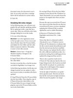
Placing a graphic
After placing and aligning a photograph in
column 1, you will reduce the size of the text
block in column 1.
1 Scroll to view the bottom of the page.
2 In column 2, locate the fourth line of text
above the bottom margin guide. From the
horizontal ruler, drag down to create a hori-
zontal ruler guide aligned with the baseline
of this line of text.
BELLA
COOLA
Coola Northern Pointe site. Consultants’ re-
ports regarding structural considerations and
tltiilddfthiti
gy. Additionally, natural illumination of below
grade spaces would significantly improve
th lit f th i d i t d
The Bella Coola Development Study
merges community requirements for the
envisioned facility and the alternative
approaches to building on the Bella
ect
P
la
n
would
be
largely
accommodated
below
grade, and that above grade structures would
be intended to accommodate those func-
tions demanding particular visibility and
identity, such as a community recreation
center.
It is very possible that significant heating
and cooling economies would be achieved
by virtue of underground construction and
the application of appropriate solar collec-
tion techniques. The southern face of pro
orientation for collection of solar energy. Ad-
ditionally, natural illumination of below grade
in
25
feet
of
the
perimeter
of
the
trees
root
sys
tems. Consequently, an area of some 185 feet
by 320 feet would be excluded from develop-
ment plans in an effort to preserve the grove
of Douglas Fir trees.
Preliminary analysis of the site has indi-
cated that it would be feasible to construct
three below grade levels. However, structural
considerations of excavation and proximity to
adjoining buildings may be reviewed. With
these parameters in mind, it can be calculated
that, for below grade construction alone, there
is cubage available to accommodate 273,650
square feet of space in three levels. This as-
Pr
LESSON 3
104
Project proposal
To allow for a 3-line caption, you will use
this horizontal ruler guide to align the bot-
tom edge of the photograph with the base-
line of text in column 2.
Note: Unless you want to place an inline
graphic (a graphic attached to text), it’s a good
idea to make sure the text does not contain an
insertion point when importing a graphic.
3 Select the pointer tool to ensure that the
text doesn’t contain an insertion point.
4 Choose File > Place. Double-click the
03ArtA.tif file in the 03Lesson folder.
5 With the loaded graphic icon displayed,
click in column 1 to place the photograph.
Depending on where you clicked, the
photograph overlaps the text in one or both
columns.
6 With the photograph still selected, drag it
until its bottom edge snaps to the horizontal
ruler guide you just created, with its right
edge snapped to the right edge of column 1.
The photograph extends into the left
margin.
With the photograph aligned, you are ready
to resize the text block in column 1.
7 With the pointer tool selected, click the
text above the photograph in column 1 to
select it as a text block, and drag the bottom
windowshade handle to display the last line
of text to be approximately one line space
above the photograph.
Column 1 displays 14 lines of proposal text.
8 Choose File > Save.
Editing the default Caption style
Once the caption text is placed below the
photograph, you will edit the default Cap-
tion style and apply it to the text.
1 Choose Layout > Autoflow to deselect it.
2 Choose File > Place, double-click the
03TextB.doc file in the 03Lesson folder.
Coola Northern Pointe site. Consultants’ re-
ports regarding structural considerations and
tree evaluation are included for their conti-
nued application to the problem. An effort has
been made to work with the full extent of
space requirements currently voiced by the
Western Division Management Center and the
Bella Coola Village Organization. Other organ-
izations were queried to form the basis of
judgment in determining the overall need. This
recognizes that as the program development
progresses, tenant requirements may change,
but the essential square footage and cubic
limitations for a below grade structure will re-
main. In addition, it has been envisioned that
jointly required facilities would be available
for all organizations to use on a shared basis,
utilizing movable walls for privacy.
In utilizing the Northern Pointe site, it is
initially assumed that the envisioned facilities
would be largely accommodated below
grade, and that above grade structures would
be intended to accommodate those func-
tions demanding particular visibility and
identity, such as a community recreation
center.
It is very possible that significant heating
and cooling economies would be achieved
by virtue of underground construction and
the application of appropriate solar collec-
tion techniques. The southern face of pro
orientation for collection of solar energy. Ad-
ditionally, natural illumination of below grade
spaces would significantly improve the quali-
ty of the indoor environment and has been
recognized as an important component of the
project.
Available Space Analysis
On the schematic site plan of the North-
ern Pointe site, a total area of some 200 feet
by 450 feet is indicated as the proposed max-
imum extent of below grade development. In
addition, we believe that a 345 feet by 475 feet
area to the north of the community center may
be considered for future inclusion in Northern
Pointe development plans, although it is not
under consideration in this study.
Preservation of thirty-one major trees
identified in the northeast corner of the site
would significantly reduce the total space
available for development. It is recommended
that the soil should remain undisturbed with-
in 25 feet of the perimeter of the trees’ root sys-
tems. Consequently, an area of some 185 feet
by 320 feet would be excluded from develop-
ment plans in an effort to preserve the grove
of Douglas Fir trees.
Preliminary analysis of the site has indi-
cated that it would be feasible to construct
three below grade levels. However, structural
considerations of excavation and proximity to
adjoining buildings may be reviewed. With
these parameters in mind, it can be calculated
that, for below grade construction alone, there
is cubage available to accommodate 273,650
square feet of space in three levels. This as-
BELLA COOLA
The Bella Coola Development Study
merges community requirements for the
envisioned facility and the alternative
approaches to building on the Bella
Project
Plan
1
BELLA COOLA
Coola Northern Pointe site. Consultants’ re-
ports regarding structural considerations and
tree evaluation are included for their contin-
tinued application to the problem. An effort
has been made to work with the full extent
of space requirements currently voiced by
the Western Division Management Center
and the Bella Coola Village Organization. Oth-
er organizations were queried to form the
basis of judgment in determining the overall
need. This recognizes that as the program
development progresses, tenant require-
ments may change, but the essential square
footage and cubic limitations for a below
grade structure will remain. In addition, it has
been envisioned that jointly required facili-
ties would be available for all organizations
to use on a shared basis, utilizing movable
walls for privacy.
In utilizing the Northern Pointe site, it is
initially assumed that the envisioned facilities
would be largely accommodated below
grade, and that above grade structures would
be intended to accommodate those func-
tions demanding particular visibility and
identity, such as a community recreation
center.
It is very possible that significant heating
and cooling economies would be achieved
by virtue of underground construction and
the application of appropriate solar collec-
tion techniques. The southern face of pro-
posed structures along Grant Road offer opti-
mum orientation for collection of solar ener-
gy. Additionally, natural illumination of below
grade spaces would significantly improve
the quality of the indoor environment and
has been recognized as an important com-
ponent of the project.
Available Space Analysis
On the schematic site plan of the North-
ern Pointe site, a total area of some 200 feet
by 450 feet is indicated as the proposed
maximum extent of below grade develop-
ment. In addition, we believe that a 345 feet
by 475 feet area to the north of the commun-
ity center may be considered for future in-
The Bella Coola Development Study
merges community requirements for the
envisioned facility and the alternative
approaches to building on the Bella
Project
Plan
1