Adobe PageMaker 7.0 Classroom in a Book- P5 potx
Bạn đang xem bản rút gọn của tài liệu. Xem và tải ngay bản đầy đủ của tài liệu tại đây (494.44 KB, 30 trang )
LESSON 3
110
Project proposal
icon (wrap all sides) is selected. Type 0 for
Bottom (leave the other Standoff values at
their default setting), and click OK.
A rectangular graphic boundary (dotted
line) frames the illustration, with the text
flowing around the edges of the graphic
boundary within both columns. You will
customize the shape of this graphic bound-
ary to allow the text to flow around the illus-
tration with greater precision.
3 Position the cursor at the bottom edge of
the graphic boundary (dotted line) and the
right edge of column 1, and click.
An additional handle is displayed on the
graphic boundary. (If you do not see a new
handle, click again more quickly.)
4 Position the pointer on the bottom left
corner handle of the graphic boundary, hold
down Shift (to constrain the movement),
and drag the corner graphic handle up until
it is aligned with the baseline of the fourth
line of text in column 1.
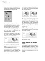
The custom text wrap allows the text to flow
around the text wrap boundary. However,
although the text is wrapping to the bound-
ary, a portion of the graphic (its white back-
ground) is on top of the text, obscuring it.
Yo u will send the graphic to the back of the
stacking order.
5 Choose Element > Arrange > Send to
Back to stack the illustration behind the text
and graphic elements.
6 Choose File > Save.
Placing, formatting, and aligning a
caption
You will place, format, and align a caption to
be displayed below the illustration at the top
of column 2. Before placing the caption text,
you will reduce the size of the text block in
column 2 to make some space for the 3-line
caption.
Coola Northern Pointe
site. Consultants’ reports re-
garding structural considera-
tions and tree evaluation are
included for their continued
application to the problem.
An effort has been made to
work with the full extent of
space requirements currently
voiced by the Western Divi-
sion Management Center and the Bella Coola
Village Organization. Other organizations were
queried to form the basis of judgment in de-
tity, such as a community recreation center.
It is very possible that significant heating
and cooling economies would be achieved by
t
lan
2
r
vation of thirty-one
e
s identified in the
corner of the site
i
gnificantly reduce
s
pace available for
ent. It is recom-
h
at the soil should
d
isturbed within 25
e
perimeter of the
t
systems. Conse-
n
area of some 185 feet by 320 feet
excluded from development plans
r
t to preserve the grove of Douglas
height of new construction to a
to 28 feet above grade, and to
serve the present garden enviro
n
o
f thirty-one
i
fied in the
of the site
n
tly reduce
a
vailable for
recommended
uld remain undis-
f
eet of the perimeter
s
ystems. Consequently,
85 feet by 320 feet would
development plans in an
e
the grove of Douglas Fir
to 28 feet above grade, and to largely
serve the present garden environment o
site. It should be noted that extensive a
b
Preservation of thirty-one
major trees identified in the
northeast corner of the site
would significantly reduce
the total space available for
development. It is recommended
that the soil should remain undis-
turbed within 25 feet of the perimeter
of the trees’ root systems. Consequently,
an area of some 185 feet by 320 feet would
be excluded from development plans in an
effort to preserve the grove of Douglas Fir
trees.
to 28 feet above grade, and to largely pre-
serve the present garden environment of the
site. It should be noted that extensive above
t
lan
2
111
ADOBE PAGEMAKER 7.0
Classroom in a Book
1 In column 1, locate the third line of the
second paragraph. Then, from the hori-
zontal ruler, drag to create a horizontal ruler
guide that is aligned with the baseline of that
third line (Y equals approximately 3.4 inches
in the Control palette).
To make room for the caption, you’ll align
the first line of proposal text in column 2
with this baseline. You’ll start by dragging its
top windowshade handle down, below the
text wrap boundary, so the text block is eas-
ier to position.
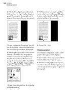
2 With the pointer tool selected, select the
proposal text in column 2 as a text block,
and drag the top windowshade handle down
until one line of text displays above the hor-
izontal ruler guide you just created. Then,
holding down Shift (to constrain the move-
ment), drag the text block so the baseline
of the first line of text aligns with the ruler
guide.
You are ready to place the caption text.
3 Choose File > Place, and double-click the
03TextD.doc file in the 03Lesson folder.
4 With the loaded text icon displayed, click
in column 2 (below the illustration) to place
the text.
Before aligning the caption text, you will
apply the Caption style.
5 Select the text tool (), and click the
caption text to establish an insertion point.
6 In the Styles palette, click Caption to
apply a style to the text.
7 From the horizontal ruler, drag to create a
horizontal ruler guide aligned with the base-
line of text closest to the 3.02 inch mark in
column 1.
You will use this horizontal ruler guide to
align the caption text with the text in
column 1.
8 Select the pointer tool, and click the cap-
tion to select it as a text block. Then drag the
text block until the baseline of the last line of
text is aligned with the horizontal ruler
guide you just created.
9 Select the hand tool (), position the tool
over the page at the bottom of the
publication window, and drag the page up.
Keeping dragging until you see the bottom
of the page.
10 If the last line of text in column 2 does
not rest on the baseline, select the pointer
tool, and click the text in column 2 to select
it as a text block. Then drag the bottom win-
dowshade handle so it snaps to the margin
guide and the last line of text rests on the
margin guide.
The second page of this publication is
completely assembled.
wou
ld
signi
f
icant
l
y re
d
uce t
h
e
total space available for devel-
opment. It is recommended that
the soil should remain undisturbed
within 25 feet of the perimeter of the
trees’ root systems. Consequently, an area
of some 185 feet by 320 feet would be exclud-
ed from development plans in an effort to pre-
serve the grove of Douglas Fir trees.
Preliminary analysis of the site has indi-
cated that it would be feasible to construct
three below grade levels. However, structural
considerations of excavation and proximity to
adjoining buildings may be reviewed. With
these parameters in mind, it can be calculated
that, for below grade construction alone,
there is cubage available to accommodate
273 650 f f i h l l
site. It should be noted that extensive above
grade construction would impair efforts to
provide natural illumination for below grade
spaces. Automobile ramp access from Grant
Road to below grade parking will need to be
given further consideration as well.
ect
P
lan
wou
ld
signi
f
icant
l
y re
d
uce t
h
e
total space available for devel-
opment. It is recommended that
the soil should remain undisturbed
within 25 feet of the perimeter of the
trees’ root systems. Consequently, an area
of some 185 feet by 320 feet would be exclud-
ed from development plans in an effort to pre-
serve the grove of Douglas Fir trees.
Preliminary analysis of the site has indi-
cated that it would be feasible to construct
three below grade levels. However, structural
considerations of excavation and proximity to
adjoining buildings may be reviewed. With
these parameters in mind, it can be calculated
that, for below grade construction alone,
there is cubage available to accommodate
273 650 f f i h l l
site. It should be noted that extensive above
grade construction would impair efforts to
provide natural illumination for below grade
spaces. Automobile ramp access from Grant
Road to below grade parking will need to be
given further consideration as well.
An open design: interior plan of lower level
conference room utilizes moving dividing
walls to create privacy amongst community.
ect
P
lan
LESSON 3
112
Project proposal
11 Choose View > Fit in Window.
12 Choose File > Save.
Assembling the third page
After formatting and aligning the text on the
third page, you will draw a box that will
serve to frame an illustration. This boxed
illustration and its corresponding caption
will span the width of both columns.
Applying styles
You will apply the same styles to the text on
the third page as you did on the previous
pages.
1 Click the page 3 icon to view the third
page of the publication.
As before, all master-page elements are
displayed within the bounds of the third
page.
2 If there is no text in column 1 on page 3,
click the page 2 icon to view the second page,
click the text in column 2 with the pointer
tool to select it as a text block, and click the
red triangle at the bottom of the text block to
load the remaining text. Then click the page
3 icon to view the third page. Let the loaded
text icon snap to the margin guides in the
top left corner of column 1, and then click to
place the text.
3 With the pointer tool selected, click the
text in column 1 to select it as a text block.
The red triangle in the bottom window-
shade handle indicates there is more text to
be placed. Before manually flowing the
remaining text into column 2, you will for-
mat the text in column 1.
4 Select the text tool (), and click the sub-
head Conclusions to establish an insertion
point. (Zoom in first if necessary.) In the
Styles palette, click Subhead 1.
5 With the text tool still selected, click the
first paragraph below the subhead text you
just formatted to establish an insertion
point in the paragraph. In the Styles palette
click, No Indent.
With the type and paragraph specifications
applied to the text, you are ready to align
the text.
6 Choose File > Save.
Skylights, balconies, and sunken gardens
provide light to below grade levels.
Preservation of thirty-one
major trees identified in the
northeast corner of the site
would significantly reduce the
total space available for devel-
opment. It is recommended that
the soil should remain undisturbed
within 25 feet of the perimeter of the
trees’ root systems. Consequently, an area
of some 185 feet by 320 feet would be exclud-
ed from development plans in an effort to pre-
serve the grove of Douglas Fir trees.
Preliminary analysis of the site has indi-
cated that it would be feasible to construct
three below grade levels. However, structural
considerations of excavation and proximity to
adjoining buildings may be reviewed. With
these parameters in mind, it can be calculated
that, for below grade construction alone,
there is cubage available to accommodate
273,650 square feet of space in three levels.
This assumes that recommended measures
would be taken to preserve the Douglas Fir
trees, and utilized in the design.
The extent of above grade construction is
constrained by a desire to limit the maximum
height of new construction to about 25 feet
to 28 feet above grade, and to largely pre-
serve the present garden environment of the
site. It should be noted that extensive above
grade construction would impair efforts to
provide natural illumination for below grade
spaces. Automobile ramp access from Grant
Road to below grade parking will need to be
given further consideration as well.
LIGHT AND VIEW CONSIDERATIONS
There is little doubt that the facility envi-
sioned for the Northern Pointe site will largely
rely upon adequate introduction of natural
light and view to the underground levels to
achieve a comfortable and successful indoor
environment. This could be accomplished
through the use of sunken gardens which
would adjoin below grade working areas to
provide light as well as important visual ori-
entation and variety. It can be recognized that
sunken gardens or other light-searching ar-
chitectural elements will require substantial
space to be fully effective.
A recent study of such underground ar-
chitectural spaces notes that many of the
kinds of space with which we are dealing,
would, “because of the dominant modes of
activity within them, require relief by physical
or visual connection to adjacent high activity
areas or the external environment, or both.
Characteristic occupancy of such spaces
would by relatively secondary and routinized.
Characteristic examples of such spaces would
be conference centers, classrooms, and offic-
es” (superscript 1 here).
It is our judgment that the quantity and
quality of natural light and external views
deemed adequate for underground spaces in
the Northern Pointe Development cannot be
established with certainty, owing to the pre-
liminary nature of this study and the large
An open design: interior plan of lower level
conference room utilizes moving dividing
walls to create privacy amongst community.
Project
Plan
2
ed
on
the
basis
of
approximate
judgment
in
lieu of more fixed guidelines. To this end, 15%
of the total gross floor area, or some 42,500
square feet, is allocated for natural light and
view throughout the underground areas. We
expect that during further development of
this project, new information may suggest
some adjustment of this allocation.
CONCLUSIONS
Preceding analysis has delineated the clear
limitations of space available for development
below grade on the Northern Pointe site. At
this juncture it would appear reasonable to
expect that 166,350 square feet of space
could be accommodated below grade, easily
accommodating the three-level design. Fur-
ther expansion below grade to the north of
ject
P
la
n
113
ADOBE PAGEMAKER 7.0
Classroom in a Book
Manually flowing text into a column
Because the illustration and caption will
extend across the bottom portion of both
columns, you will resize the text block in
column 1, and manually flow the remaining
text into column 2.
Before reducing the size of the text block in
column 1, you will create a horizontal ruler
guide aligned with text in column 1. You will
eventually use this horizontal ruler guide to
align the bottom edge of the box that con-
tains an illustration, allowing enough space
for a single-line caption.
1 From the horizontal ruler, drag to create a
horizontal ruler guide aligned with the base-
line of the second line of text above the
bottom margin guide.
After drawing the box that will frame the
illustration, you will use this horizontal
ruler guide to align the box.
2 From the horizontal ruler, drag to create a
horizontal ruler guide aligned with the base-
line of text nearest to the 5.9-inch mark on
the vertical ruler.
3 Select the pointer tool, click the text in
column 1 to select it as a text block, and drag
the bottom windowshade handle just below
the line of text aligned with the horizontal
ruler guide you just created.
As before, the red triangle in the bottom
windowshade handle indicates all text is not
displayed.
4 Click the red triangle in the bottom win-
dowshade handle to load the remaining text
in the story.
5 With the loaded text icon displayed, posi-
tion the icon in the top left corner of column
2, letting it snap to the column and margin
guides. Click to place the text.
The empty bottom windowshade handle of
the text block in column 2 indicates the end
of the story.
Depending upon how precise you were
when you placed the graphics and text
throughout this project, the lines may not
end in exactly the same spot. Make sure the
first line of each text block on this page
aligns. Do not worry if one text block is a few
lines longer than the other.
6 Choose File > Save.
b
e
l
ow gra
d
e on t
h
e
N
ort
h
ern
P
o
i
nte s
i
te.
A
t
this juncture it would appear reasonable to ex-
pect that 166,350 square feet of space could
be accommodated below grade, easily accom-
modating the three-level design. Further ex-
pansion below grade to the north of the Grant
Community Center may constitute valuable
space available for further development,
although it has not been studied herein or in-
cluded in available space estimates.
Although the constraints on above grade
construction do not directly translate into
ro
je
ct
Pl
number of unresolved controlling factors. Yet
it is evident that space will be required and
must be set aside for natural light.
Accordingly, we believe that space for
natural light and view must be initially allocat-
ed on the basis of approximate judgment in
lieu of more fixed guidelines. To this end, 15%
of the total gross floor area, or some 42,500
square feet, is allocated for natural light and
view throughout the underground areas. We
expect that during further development of
this project, new information may suggest
some adjustment of this allocation.
t
lan
3
b
e
l
ow gra
d
e on t
h
e
N
ort
h
ern
P
o
i
nte s
i
te.
A
t
this juncture it would appear reasonable to ex-
pect that 166,350 square feet of space could
be accommodated below grade, easily accom-
modating the three-level design. Further ex-
pansion below grade to the north of the Grant
Community Center may constitute valuable
space available for further development,
although it has not been studied herein or in-
cluded in available space estimates.
Although the constraints on above grade
construction do not directly translate into
matc
h
t
h
e space ava
il
a
bl
e
f
or
d
eve
l
opment.
There is considerable leeway for adjust-
ment of the siting and configuration of the
above grade buildings under consideration.
At this level of investigation, only schematic
studies of this question can be undertaken. A
number of schemes of massing options have
been studied, and the strongest two have
been selected for illustration to suggest alter-
nate ways to approach this unique problem.At
this stage, it is suggested that the recom-
mendations in this study be equally reviewed.
ro
je
ct
Pl
LESSON 3
114
Project proposal
Drawing a box
After creating a box that will frame the final
illustration, you will align it with an existing
horizontal ruler guide.
1 Select the rectangle tool (), and drag to
draw a box below the proposal text,
spanning the width of the two columns
(exact height is not important).
2 In the Control palette, type 3.87 for H,
and press Enter or Return to establish the
height for the box.
3 With the box still selected, choose
Element > Stroke > Hairline to assign a
stroke style and weight to the line of the box.
4 Select the pointer tool, position the
pointer on the edge of the box, hold down
Shift (to constrain the movement), and drag
the box until its bottom edge snaps to the
horizontal ruler guide you created, with the
left and right edges of the box still aligned
with the margin guides.
Since the bottom of the box is aligned with
what was the baseline of the second line of
text above the bottom margin guide, you
have provided enough space for the single-
line caption.
5 Choose File > Save.
Placing a graphic and caption
After placing the final illustration, you will
place, format, and align its corresponding
caption.
This illustration was resized in Adobe
Photoshop, and saved in TIFF file format
with a resolution of 100 dpi.
1 Choose File > Place, and double-click the
03ArtD.tif file in the 03Lesson folder.
2 With the loaded graphic icon displayed,
click within the hairline box to place the
illustration.
number of unresolved controlling factors. Yet
it is evident that space will be required and
must be set aside for natural light.
Accordingly, we believe that space for
natural light and view must be initially allocat-
ed on the basis of approximate judgment in
lieu of more fixed guidelines. To this end, 15%
of the total gross floor area, or some 42,500
square feet, is allocated for natural light and
view throughout the underground areas. We
expect that during further development of
this project, new information may suggest
some adjustment of this allocation.
CONCLUSIONS
Preceding analysis has delineated the clear
limitations of space available for development
below grade on the Northern Pointe site. At
this juncture it would appear reasonable to ex-
pect that 166,350 square feet of space could
be accommodated below grade, easily accom-
modating the three-level design. Further ex-
pansion below grade to the north of the Grant
Community Center may constitute valuable
space available for further development,
although it has not been studied herein or in-
cluded in available space estimates.
Although the constraints on above grade
construction do not directly translate into
clear limitations of available space, examina-
tion of a range of options has led to a recom-
mendation to accommodate 32,000 square
feet of space in two buildings above grade. In
the time frame of Northern Pointe develop-
ment it is felt that the Douglas Fir trees alone
would merit preservation during construction,
although replacement planting of a number
of major trees is envisioned to follow con-
struction. The current space planning figures
reflect these assumptions.
The resulting total 253,850 gross square
feet of space estimated to be available for de-
velopment exceeds the current requirements
of 250,000 square feet by a moderate amount.
We would not necessarily suggest any further
increase in the program size to more closely
match the space available for development.
There is considerable leeway for adjust-
ment of the siting and configuration of the
above grade buildings under consideration.
At this level of investigation, only schematic
studies of this question can be undertaken. A
number of schemes of massing options have
been studied, and the strongest two have
been selected for illustration to suggest alter-
nate ways to approach this unique problem.At
this stage, it is suggested that the recom-
mendations in this study be equally reviewed.
Project
Plan
3
115
ADOBE PAGEMAKER 7.0
Classroom in a Book
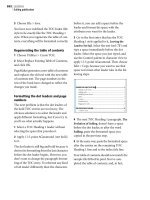
3 With the illustration still selected, drag
it until it is visually centered in the hair-
line box.
4 Choose File > Place, and double-click the
03TextE.doc file in the 03Lesson folder.
To make the caption text span the image
area, you will drag to define a text block that
spans both columns.
5 With the loaded text icon displayed, drag
to define a text block under the boxed illus-
tration that spans both columns to place the
caption (exact height is not important).
6 Select the text tool (), and click the cap-
tion text to establish an insertion point. In
the Styles palette, click Caption.
7 Select the pointer tool, click the caption
text to select it as a text block, and drag the
bottom windowshade handle until the
entire story is displayed. Then hold down
Shift (to constrain the movement), and drag
the text block until the baseline of the text is
aligned with the bottom margin guide.
You have completed assembling the entire
proposal.
8 Choose View > Fit in Window.
9 Choose View > Hide Guides to hide the
column, ruler, and margin guides used to
assemble this proposal.
10 Choose File > Save to save the
03Work.pmd publication.
number of unresolved controlling factors. Yet
it is evident that space will be required and
must be set aside for natural light.
Accordingly, we believe that space for
natural light and view must be initially allocat-
ed on the basis of approximate judgment in
lieu of more fixed guidelines. To this end, 15%
of the total gross floor area, or some 42,500
square feet, is allocated for natural light and
view throughout the underground areas. We
expect that during further development of
this project, new information may suggest
some adjustment of this allocation.
CONCLUSIONS
Preceding analysis has delineated the clear
limitations of space available for development
below grade on the Northern Pointe site. At
this juncture it would appear reasonable to ex-
pect that 166,350 square feet of space could
be accommodated below grade, easily accom-
modating the three-level design. Further ex-
pansion below grade to the north of the Grant
Community Center may constitute valuable
space available for further development,
although it has not been studied herein or in-
cluded in available space estimates.
Although the constraints on above grade
construction do not directly translate into
clear limitations of available space, examina-
tion of a range of options has led to a recom-
mendation to accommodate 32,000 square
feet of space in two buildings above grade. In
the time frame of Northern Pointe develop-
ment it is felt that the Douglas Fir trees alone
would merit preservation during construction,
although replacement planting of a number
of major trees is envisioned to follow con-
struction. The current space planning figures
reflect these assumptions.
The resulting total 253,850 gross square
feet of space estimated to be available for de-
velopment exceeds the current requirements
of 250,000 square feet by a moderate amount.
We would not necessarily suggest any further
increase in the program size to more closely
match the space available for development.
There is considerable leeway for adjust-
ment of the siting and configuration of the
above grade buildings under consideration.
At this level of investigation, only schematic
studies of this question can be undertaken. A
number of schemes of massing options have
been studied, and the strongest two have
been selected for illustration to suggest alter-
nate ways to approach this unique problem.At
this stage, it is suggested that the recom-
mendations in this study be equally reviewed.
3
Project
Plan
Pr
Above is a detail from the proposed expansion plan to north of the Grant Community Center.
Pr
number of unresolved controlling factors. Yet
it is evident that space will be required and
must be set aside for natural light.
Accordingly, we believe that space for
natural light and view must be initially allocat-
ed on the basis of approximate judgment in
lieu of more fixed guidelines. To this end, 15%
of the total gross floor area, or some 42,500
square feet, is allocated for natural light and
view throughout the underground areas. We
expect that during further development of
this project, new information may suggest
some adjustment of this allocation.
CONCLUSIONS
Preceding analysis has delineated the clear
limitations of space available for development
below grade on the Northern Pointe site. At
this juncture it would appear reasonable to ex-
pect that 166,350 square feet of space could
be accommodated below grade, easily accom-
modating the three-level design. Further ex-
pansion below grade to the north of the Grant
Community Center may constitute valuable
space available for further development,
although it has not been studied herein or in-
cluded in available space estimates.
Although the constraints on above grade
construction do not directly translate into
clear limitations of available space, examina-
tion of a range of options has led to a recom-
mendation to accommodate 32,000 square
feet of space in two buildings above grade. In
the time frame of Northern Pointe develop-
ment it is felt that the Douglas Fir trees alone
would merit preservation during construction,
although replacement planting of a number
of major trees is envisioned to follow con-
struction. The current space planning figures
reflect these assumptions.
The resulting total 253,850 gross square
feet of space estimated to be available for de-
velopment exceeds the current requirements
of 250,000 square feet by a moderate amount.
We would not necessarily suggest any further
increase in the program size to more closely
match the space available for development.
There is considerable leeway for adjust-
ment of the siting and configuration of the
above grade buildings under consideration.
At this level of investigation, only schematic
studies of this question can be undertaken. A
number of schemes of massing options have
been studied, and the strongest two have
been selected for illustration to suggest alter-
nate ways to approach this unique problem.At
this stage, it is suggested that the recom-
mendations in this study be equally reviewed.
Above is a detail from the proposed expansion plan to north of the Grant Community Center.
Project
Plan
3
LESSON 3
116
Project proposal
Producing the proposal
As mentioned at the beginning of this les-
son, you can print this publication success-
fully on any 300 dpi or 600 dpi desktop laser
printing device, and then photocopy it as
needed. Or you can Export to Adobe PDF as
described in Creating an Adobe PDF version
of the flyer on page 41.
1 Choose File > Print to open the Print
Document printing box for the type of
printer you selected.
2 In the Print Document dialog box, click
Color. Make sure the Composite and Gray-
scale options are selected.
3 Click Print to print the proposal.
4 Close all open publications, and choose
File > Exit (Windows) or File > Quit
(Macintosh) to exit the PageMaker
application.
Review questions
1 List two advantages to using styles.
2 How do you make every object you will
draw in a PageMaker publication have the
same stroke width, color, and fill?
3 What is the term that refers to the vertical
space used by each line of type?
4 What is a quick way to close multiple
dialog boxes with a single click?
5 What is an advantage of placing text with
Autoflow on?
Answers
1 Styles let you do the following:
• Maintain a consistent look throughout the
publication.
• Ensure accuracy so that different
paragraphs all have exactly the same
specifications.
• Simplify and speed up formatting.
2 Click the pointer tool to deselect all
objects, and then set the stroke and fill
options you want using the Element menu
and/or the Colors palette. These settings
affect all objects you draw in that publica-
tion from this point forward but do not
affect existing objects.
3 Slug.
4 Hold down Shift (Windows) or Option
(Macintosh) and click OK or Cancel.
5 With Autoflow on, PageMaker fills all
columns and creates new pages as needed
without manual intervention.
Lesson 4
Jewelcase booklet
In this lesson you will create the eight-page
booklet titled Architectural Treasures of Italy,
featuring eight color photographs of historic
Italy. For best results, this booklet needs to be
printed on a printing press. To print color art
on a commercial printing press, your service
provider will separate each page containing
composite art into its component colors by
creating a film separation on an imagesetter
for
each ink–cyan, magenta, yellow, black
(CMYK), and any spot colors. A commercial
printer uses these film separations to create the
printing plates used on the press.
LESSON 4
118
Jewelcase booklet
Designed to accompany a CD-ROM, this
publication fits in the front cover of a
CD-ROM jewelcase. It’s easy to get the right
dimensions, because the PageMaker appli-
cation includes a page size already estab-
lished for this exact purpose. Before printing
this booklet on a commercial printing press,
you must specify a custom paper size larger
than the page size to accommodate the
printer’s marks (cropping marks) and page
information.
This lesson covers:
• Specifying columns of unequal width
• Wo rking with layers
• Creating a bordered frame
• Reversing text out of a frame
• Adding rules to a paragraph
• Flowing text semiautomatically
• Modifying an image using the Image
Control command
It should take you approximately 2 hours to
complete this lesson.
Before you begin
All files and fonts needed to assemble this
booklet are found on the Adobe PageMaker
Classroom in a Book CD-ROM in the folders
04Lesson and Fonts, respectively.
Note: Windows users need to unlock the
lesson files before using them. For infor-
mation, see Copying the Classroom in a
Book files on page 4.
Opening an existing document
Let’s take a look at the final version of the
booklet you will create in this lesson.
1 Before launching PageMaker, return all
settings to their defaults, deleting the
PageMaker 7.0 preferences file. See
“Restoring default settings” in Lesson 1.
2 In addition to the commonly-used fonts
listed in the Getting Stated chapter, make
sure AGaramond, AGaramond Bold, AGar-
amond Semibold Italic, and Birch are
installed.
Windows only: Because of the way Windows
handles fonts, AGaramond Semibold Italic
appears in the ATM Fonts list as AGaramond,
Bold Italic (notice the comma). However,
neither AGaramond Semibold Italic nor
AGaramond, Bold Italic appear in font menus
in Windows applications. You must apply bold
and italic to AGaramond to use AGaramond
Semibold Italic.
3 Launch PageMaker.
4 Choose File > Open, and double-click the
04Final.pmd file in the 04Lesson folder.
Architectural
Treasures
of Italy
A Photographic Reference of Palaces, Churches, and Ruins
119
ADOBE PAGEMAKER 7.0
Classroom in a Book
The full view of the first page displays a vari-
ety of text and graphic elements. The page
icons indicate the booklet consists of eight
pages.
5 If the publication window does not fill the
screen, click the Maximize button in the title
bar to expand the window.
6 Click the page icons to page through the
booklet, and then click the page 1 icon to
display the first page.
7 Choose View > Show Guides to display
the guides used to assemble this booklet.
Talk with your printer
Designed to be printed on a commercial
printing press, this booklet features images
that were saved as CMYK TIFF files, making
it easier to create the film separations.
To reduce the demand for disk space on your
system, these images were scanned at a reso-
lution of 100 dpi. Since it is likely that your
printer would recommend printing this sort
of publication at a line screen frequency of
150 lpi, in a real environment these images
would have to be scanned at 300 dpi (double
the selected line screen frequency) to meet
the printing requirements of this publica-
tion.
To successfully print a design like this one,
which has images that touch the edge of the
page, you must allow the images to extend or
bleed beyond the trim marks of the page. A
bleed allows for inaccuracies of the press and
trimming equipment. Your printer can tell
you the optimum bleed size for this job. So
that you can better visualize the printed
piece, the images in 04Final.pmd do not
bleed, nor will they bleed in the version you
create.
As discussed in lesson 2, adjacent colored
objects in a design require trapping. After
verifying the trapping specification, the size
of the bleed, and the line screen frequency
with your printer, talk with your service pro-
vider to determine who will perform the
prepress tasks and how you should deliver
this publication to your service provider.
Assembling the master page
For these left and right master pages, you
will specify column guides, create graphic
elements, and specify automatic page num-
bering.
Creating a new publication
After setting the options in the Document
Setup dialog box, you will save and name
your publication.
1 Choose File > New, and choose Compact
Disc for Page Size. Type 8 for Number of
Pages, type .25 for Inside, .25 for Outside,
.329 for Top, and .329 for Bottom to set the
margin guides. Set the Target Output Reso-
lution to 2400 dpi, and choose (Windows
only) the AGFA-ProSet9800 for Compose to
Printer. Then click OK.
Note: If you do not have the required printer,
you can still create the project as directed and
then
print it on your own printer by
LESSON 4
120
Jewelcase booklet
selecting your printer and its PPD (if it is a
PostScript printer) in the Print dialog box
when it is time to print.
Yo u can also use the
Export Adobe PDF command to create an
Adobe PDF version of the project rather than
a printed copy, as described in Creating an
Adobe PDF version of the flyer on page 41.
The publication window displays the first
page of the untitled publication with the
specified page dimensions and margin
guides. Unless you specify otherwise, page
number 1 of a double-sided publication is
assigned to the first right page in the publi-
cation.
2 Choose File > Save As, and type
04Work.pmd for Name, open the 04Lesson
folder if necessary, and click Save.
3 Click the page 2 icon to view the second
and third facing pages.
The zero point is aligned with the intersec-
tion of the top, inside edges of the facing
pages. (In previous lessons, you assembled
single-sided publications, where the zero
point is aligned with the top left corner of
the page.)
Establishing preferences
Because you use the rulers to set up guides,
it’s a good idea to choose a measurement
system before you begin laying out your
pages.You’ll also reduce the size below which
PageMaker displays text as gray lines in lay-
out view.
1 Choose File > Preferences > General.
To open the Preferences dialog
box, double-click the pointer tool.
2 In the Preferences dialog box, choose
Picas for both Measurements In and Vertical
Ruler, and then click More.
Remember: 22p9 means 22 picas and 9
points.
3 0124 0124
123 0
Zero point
121
ADOBE PAGEMAKER 7.0
Classroom in a Book
3 In the More Preferences dialog box, set
Greek Text Below to 3. Leave all other set-
tings at their default values. Hold down Shift
(Windows) or Option (Macintosh), and
click OK to close the dialog boxes.
Specifying columns of unequal width
PageMaker automatically creates columns of
equal width when you specify multiple col-
umns. In this project you will create unequal
columns, using the pointer tool to drag the
column guides to the positions you want.
1 Click the master-page icon () in the
lower left corner of the publication window.
PageMaker displays the facing master pages
and highlights the master-page icon. These
pages display the margin guides you speci-
fied in the Document Setup dialog box, with
the zero point aligned with the intersection
of the top, inside edges of the facing pages.
2 Choose Layout > Column Guides, and
type 2 for Number of Columns, select Set
Left and Right Pages Separately (just to see
that you can specify different numbers of
columns on the left and right pages), and
click OK.
PageMaker automatically creates columns of
equal widths, filling the entire image area
between the margin guides.
Yo u’ll now move the column guides. To
maintain the specified space between
columns, the guides of adjacent columns
move together. It is important that you drag
and position the correct guide. The
locations specified are for the right guide in
column 1, not the left guide of column 2.
3 Select the pointer tool (if necessary). On
the right master page, position the pointer
on the right column guide of column 1. (See
the illustration.) Then drag the column
guide until it is aligned approximately with
the 15p mark on the horizontal ruler.
6
6
12
18
24
12 18 24
LESSON 4
122
Jewelcase booklet
4 On the left master page, drag the right col-
umn guide of column 1 until it is aligned
approximately with the -13p6 mark on the
horizontal ruler.
Note: Since the left page is positioned to the
left of the zero point, all X coordinate values
for the left page are less than or equal to zero.
5 Choose File > Save.
Drawing a circle
After drawing a small circle, you will use the
Control palette to resize it, and the Colors
palette to fill it with the color black.
1 Magnify the lower left portion of the left
master page.
2 Select the ellipse tool () in the toolbox,
hold down Shift (to constrain the ellipse to a
circle), and drag to draw a small circle of any
dimension.
3 In the Control palette, make sure the Scal-
ing button is toggled to proportional scaling
(). Type 1p2 for W (width) and press Tab.
(Because you selected proportional scaling,
PageMaker automatically enters 1p2 for H.)
Press Enter or Return to resize the circle.
4 In the Colors palette click the Both button
(), and click [Black] to apply the color
black to the stroke and fill of the circle.
Placed on the master pages, the circle will
serve to frame the page numbers.
5 Choose File > Save.
Setting automatic page numbering
To number all pages in a publication
automatically, you can place page-number
markers on the master pages. After you place
the page number marker in a black circle on
the left page, you will copy and paste them to
the right page, and reverse the colors.
1 Select the text tool (), and drag to define
a text block on top of the black circle,
making it approximately the width of the
circle (exact height is not important).
If your cursor jumps to the column guide,
drag again over the circle.
You need to reverse the text so it will stand
out on the black circle. You’ll set the text
attributes before you type the page-number
marker so you can see what you type.
2 In the Control palette, choose AGara-
mond (Regular) for Font. Type 9 for Size
(), click the Bold (), and Reverse
buttons
().
Remember that when you click a button in
the Control palette, PageMaker applies any
values you’ve typed as well as the action for
the button.
Note: Because of the way fonts are defined,
when you apply bold to AGaramond,
PageMaker actually uses AGaramond Semi-
bold. On the Macintosh, you can get the same
result if you select AGaramond Semibold
directly.
3 Hold down Ctrl and Alt (Windows) or
Command and Option (Macintosh), and
press p.
123
ADOBE PAGEMAKER 7.0
Classroom in a Book
The page-number marker LM (left master)
is displayed over the black circle, indicating
where the page numbers will appear.
You will use the align objects feature in
PageMaker to center the text over the circle,
but first you need to center the text within
the text block. You will both increase the
leading, to center the page number within
the leading slug, and then change the para-
graph alignment from left justified to center.
4 With the cursor still in the text, choose
Edit > Select All. In the Control palette, type
15 for Leading
(). Click the Paragraph-
view button
() and then click the Center-
align button
().
5 Select the pointer tool, drag to select both
the black circle and the page-number
marker.
If you selected only one of the objects, drag
again, but start dragging further away so you
enclose the bounding boxes of both objects.
6 Choose Element > Align Objects
(Windows) or Element > Align
(Macintosh). Click both the vertical and
horizontal Center-Align buttons, and
click OK.
7 With the two objects still selected, select
the center reference point in the Proxy icon
in the Control palette. Type -26p3 for X and
26p11 for Y, and press the Apply button
() to align the center of the objects with
the specified coordinate position.
Remember: Unless otherwise stated, the
reference point in the Control palette Proxy
icon should be a square point, not an arrow.
8 Choose File > Save.
Copying the page-number marker
Since your publication has facing pages, you
will copy the left page-number marker, and
paste the copy on the right master page.
1 With the pointer tool selected, drag to
select both the black circle and the page-
number marker. Choose Edit > Copy.
2 Hold down Alt (Windows) or Option
(Macintosh) and double-click the zoom tool
() to switch to the fit-in-window view.
Now that both pages are visible, you can
zoom in to the area on the right page where
you’ll paste the page number marker.
3 With the zoom tool still selected, drag
across the bottom right quadrant of the
right master page.
4 Choose Edit > Paste.
LM
LESSON 4
124
Jewelcase booklet
PageMaker pastes the circle and page-num-
ber marker on the right master page. Notice
that the page-number marker automatically
changes to RM (right master).
Note: Page-number markers positioned on
the pasteboard display as PB (pasteboard).
5 With the black circle and the page-num-
ber marker still selected, in the Control pal-
ette make sure the center reference point in
the Proxy icon is selected, type 26p3 for X
and 26p11 for Y, and press Enter or Return.
Since the circle and the page-number
marker will be positioned on a black box,
you will reverse the colors of both objects.
6 Select the text tool (), and double-click
the page-number marker RM to select it. In
the Control palette, click the Character-view
button
(). Then click the Reverse button
() to deselect it (and thus change the color
back to black).
The Reverse button toggles text between the
paper color and black. Until you reverse the
circle, the page-number marker will not be
visible.
7 Select the pointer tool, hold down Ctrl
(Windows) or Command (Macintosh) and
click twice to select the black circle. (The
first click selects the text block; the second
click selects the circle.) In the Colors palette,
make sure the Both button
() is selected,
and select the color [Paper].
8 Choose File > Save.
Drawing a box
After creating the box that fills the right side
of the right master page, you will fill it with
the color black and adjust the stacking order
to stack the black box behind the circle and
the page-number marker.
1 Double-click the hand tool (). (This is
another shortcut to the fit-in-window view.)
2 Select the rectangle tool (), and draw a
box of any dimension on the right master
page.
Yo u’ll now use the Control palette to both
move it to the right edge of the page and to
resize it.
RM
RM
125
ADOBE PAGEMAKER 7.0
Classroom in a Book
3 In the Control palette, select the top right
corner reference point in the Proxy icon.
Click the Scaling button to toggle it to non-
proportional scaling
(). Type 28p4 for X,
0 for Y, 9p6 for W, and 28p6 for H, and then
press the Apply button
().
4 In the Colors palette, select the Both
button
(), and then select [Black] to
apply the color black to the stroke and fill of
the box.
The black box covers the white circle and
page-number marker.
5 With the box still selected, choose Ele-
ment > Arrange > Send to Back to stack the
black box behind the circle and the page-
number marker.
The master-page design is complete, and
you are ready to assemble the booklet cover.
6 Choose File > Save.
Assembling the booklet cover
After hiding the display of the master-page
elements on the first page (booklet cover),
you will create two layers to separate the art
and text. You’ll then divide the page into
quadrants, place four photographs, and
create the boxed title and subtitle.
Looking at layers in the final version
Before you create layers in this booklet, take
a look at how layers were used in the final
version.
1 Choose Window > 04Final.pmd to switch
to the final version of the publication. (In
Windows, the path to the file is displayed
with the file name on the Window menu.)
2 If necessary, click the page 1 icon to view
the front cover of the booklet.
3 Choose Window > Show Layers.
Layers let you separate like elements and
treat them like a unit without grouping
them. When elements are on a layer, you can
display them, hide them, lock them, or even
change their stacking order in relation to the
rest of the publication. You’ll use layers in
this booklet to speed up screen redraw and
make layout easier. After placing the photo-
graphic images on the Art layer, you’ll hide
that layer as you work on the text layer.
When you want to display both layers, you
can quickly lock one layer so you don’t have
to worry about inadvertently moving an
object.
4 Click the eye icon () of the Art layer.
LM RM
Palette men
u
Target layer
Visible and
Locked laye
r
New layer button
Lock/unlock
Show/hide
LESSON 4
126
Jewelcase booklet
PageMaker hides the Art layer throughout
the publication, not just on the displayed
page. A hidden layer also does not print.
5 Click the page 2 icon, and then click to
display the eye icon of the Art layer to again
view the images.
You can determine which layer an element is
on by selecting the element.
6 Select the image behind the table of
contents on page 2.
The layer containing the selected element
becomes the target layer. (It is highlighted
and contains the pencil icon.) The small
selection box next to the pencil icon indi-
cates that something on that layer is selected.
Notice that the color of the graphic handles
of the selected image match the color swatch
of the layer.
The three palettes you’ll use most often in
creating this booklet are the Layers, Styles,
and Colors palettes. You can combine the
three to leave more room to view your page.
7 Drag the Layers tab to the Colors and
Styles palette, and then click the Close box of
the Master Pages palette.
Creating layers
You are now ready to create two new layers
in your booklet.
1 Choose File > Close to close
04Final.pmd and to return to your
publication. If prompted to save before
closing, click No.
Your publication already contains a default
layer (called Default). Because that was the
only layer when you created the master
pages, all the master page elements automat-
ically were placed on the Default layer. You
can place master page elements on any layer,
and with the exception of stacking order,
they will behave like any other element on
the layer. However, master page elements
always display at the bottom of the stacking
order, regardless of the layer they are on.
You will leave the Master Page elements on
the Default layer.
2 Click the New Layer button () at the
bottom of the Layers palette, type Art for
Name, and click OK.
Create the next layer using the Layers palette
menu.
Selection box
Target layer
127
ADOBE PAGEMAKER 7.0
Classroom in a Book
3 Choose New Layer from the Layers palette
menu, type Text for Name, and click OK.
The stacking order of layers reflects their
order in the palette: the bottom layer in the
palette is the bottom layer in the publica-
tion. Because the text in the booklet appears
on top of the images, you created the text
layer as the top layer.
Hiding the display of master-page
elements
You can display master-page elements on a
page-by-page basis. Because the design
doesn’t use master-page elements on the
cover, you will deselect the display of the
master-page elements for the cover.
1 Click the page 1 icon to view the front
cover of the booklet.
Since master-page elements are automati-
cally displayed on each page of the publica-
tion, the first page of the publication is dis-
played with all master-page elements found
on the right master page.
You can easily hide master-page elements on
a page.
2 Choose View > Display Master Items to
deselect the option.
The text and graphic elements that you cre-
ated are not displayed, but the nonprinting
guides (margin, column, and ruler) are not
affected. If you were to print this page, none
of the master-page elements would be
printed.
Placing and cropping a graphic
After dividing the front cover into quad-
rants, you will place a photograph into each
quadrant. The photographs were prepared
in Adobe Photoshop by applying a single
color to a grayscale TIFF image, and then
sizing and saving each image in TIFF file for-
mat at a resolution of 100 dpi.
1 From the horizontal ruler, drag to create a
horizontal ruler guide at 14p3. From the
vertical ruler, drag to create a vertical ruler
guide at 14p2, dividing the booklet cover
into quadrants.
As you learned in Lesson 1, you can move
the zero point (the intersection of the hori-
zontal and vertical rulers) to any location on
the page. To make it a little easier to align the
four photographs on the cover, you will
move the zero point from the top-left corner
of the page until it is aligned with the center
of the page. Each image will have a corner
touching the zero point, making it easy to
enter their precise location in the Control
palette.
LESSON 4
128
Jewelcase booklet
2 With the pointer tool selected, position
the pointer on the crosshair of the zero
point, and drag it until the zero point is
aligned with the intersection of the ruler
guides you just created. Watch the position
in the Control palette; X should be 14p2,
and Y should be 14p3.
3 Make sure the Art layer is the target layer.
If not, click to select it.
4 Choose File > Place, and double-click the
04ArtA.tif file in the 04Lesson folder.
5 With the loaded graphic icon displayed,
click in the upper left quadrant of the page
to place the photograph.
Since the photographs extend to the edges of
the page, each photograph was sized to allow
for a bleed to overlap the edges of the page.
For the sake of viewing the actual design of
the cover, you will crop each photograph to
be aligned with the edges of the page. When
the booklet is complete, one of the prepress
tasks will be to pull the crop rectangles out
again, to reestablish the bleeds.
Before you crop, you’ll position the images.
6 In the Control palette, select the bottom
right reference point in the Proxy icon, type
0 for both X and Y, and press Enter or Return
to align the bottom right corner of the pho-
tograph with the zero point.
Precision will be important when cropping
these images for two reasons. You will copy
all the images on the cover and paste them
onto the back cover. If cropped precisely to
fit the page, they will be easier to position on
the back cover. In addition, in the final
printing of this booklet, the binding edges of
the pages will abut each other, rather than
bleed. If not cropped carefully, an image
could overlap the adjacent page in the signa-
ture or not print all the way to the page fold.
This is another example of the importance
of talking to your service provider before
you begin layout.
7 If necessary, reselect the photograph.
Select the cropping tool
(), and position
the tool over the top left graphic handle of
the photograph, making sure the graphic
handle shows through the center of the
cropping tool. Hold down the mouse button
until the tool changes to a double-headed
arrow.
6
6
12
18
24
12 18 24
129
ADOBE PAGEMAKER 7.0
Classroom in a Book
8 With the mouse button still held down,
drag down and right to the top left corner of
the page, and release the mouse button
when W in the Control palette is 14p2, and
H is 14p3.
PageMaker crops the view of the
photograph.
Placing and cropping the three
remaining graphics
As you place the three remaining photo-
graphs on the cover, crop each one to be
aligned with the edges of the page.
1 Choose File > Place, and double-click the
04ArtB.tif file in the 04Lesson folder.
2 With the loaded graphic icon displayed,
click in the upper right quadrant of the page
to place the photograph.
3 In the Control palette, select the bottom
left reference point in the Proxy icon, type 0
for both X and Y, and press Enter or Return.
4 Select the cropping tool (), and posi-
tion the tool over the top right graphic han-
dle of the photograph, and drag down and
left to the top right corner of the page. Watch
the values in the Control palette; W should
be 14p2, and H should be 14p3.
5 Choose File > Place, and double-click the
04ArtC.tif file in the 04Lesson folder.
6 With the loaded graphic icon displayed,
click in the lower left quadrant of the page to
place the photograph.
7 In the Control palette, select the top right
reference point in the Proxy icon, type 0 for
both X and Y, and press Enter or Return.
You will use the cropping tool in the Control
palette to crop the next two images.
8 Click the Cropping button () in the
Control palette. With the top right reference
point still selected, type 14p2 for W, and
14p3 for H, and click the Apply button
().
9 Choose File > Place, and double-click the
04ArtD.tif file in the 04Lesson folder.
LESSON 4
130
Jewelcase booklet
10 Position the loaded graphic icon in the
lower right quadrant of the page and let it
snap to the zero point. Then click to place
the photograph.
11 In the Control palette, select the top left
reference point in the Proxy icon, type 0 for
both X and Y. Click the Cropping button,
and type 14p2 for W, and 14p3 for H. Then
click the Apply button.
12 Choose File > Save.
Creating a bordered frame for the title
Next to the rectangle, ellipse, and polygon
tools in the toolbox, is a corresponding
frame tool. Like standard PageMaker-drawn
shapes, frames can have a stroke and fill.
Unlike standard shapes, however, frames
can also have content, either text or graph-
ics. Frames make it easy for you to position
objects and text within another shape and
can serve as placeholders in templates or
during the design phase of a publication.
You will create the title for this booklet in a
bordered frame on the text layer.
1 In the Layers palette, select the Text layer.
Then click the eye icon
() of the Art layer
to temporarily hide the images.
2 Select the rectangle frame tool (), and
drag to draw a box of any dimension in the
center of the page.
3 In the Control palette, select the center
reference point in the Proxy icon. Type 0 for
both X and Y (to center the frame on the
page), type 9p7 for both W and H (to resize
the frame), and press Enter or Return.
4 Click the Colors palette tab, make sure the
Both button
() is highlighted. Then select
[Black] to apply the color black to the stroke
and fill of the box.
5 Choose Element > Stroke > 6-pt triple
line to create a triple-line border.
You now need to set the frame options. The
frame options control the position of the
content within the frame. You can center a
text block vertically within a frame, or align
its top or bottom with the top or bottom of
the frame. You can also specify insets to off-
set text from the edges of the frame.
131
ADOBE PAGEMAKER 7.0
Classroom in a Book
6 With the frame still selected, choose
Element > Frame > Frame Options. Choose
Center for Vertical Alignment, set the Top,
Bottom, Left, and Right Insets to 0, and
click OK.
Note: Vertical Alignment and Offsets are the
only frame options that affect text. The other
options apply to graphics in a frame.
7 Choose File > Save.
Defining process colors
This booklet calls for two custom colors.
Before you define these process colors, you’ll
remove any unused colors from the palette.
1 Choose Utilities > Define Colors, and
click the Remove Unused button. When
prompted, click Yes to All to remove all
unused colors, then click OK when
PageMaker lists the number of colors and
inks removed. (Do not close the Define
Colors dialog box.)
2 In the Define Colors dialog box, click
New. Type Sand for Name, and choose
Process for Type and CMYK for Model.
Then enter the CMYK values shown below.
(You can press the Tab key to jump from one
edit box to the next. (In Windows, press Tab
twice.) After entering the Black value, press
Tab again if you want to see the final color
displayed in the color swatch.
3 Click OK, and then click New again.
4 Type Dark Blue for Name, and enter the
CMYK values shown below.
5 Hold down either Shift (Windows) or
Option (Macintosh) and click OK to close
the dialog boxes.
6 Click the Maximize button in the top of
the Colors palette to display the entire pal-
ette. (Click again if PageMaker minimizes
the palette.)
LESSON 4
132
Jewelcase booklet
PageMaker added the new colors Dark Blue
and Sand to the palette.
7 Choose File > Save.
Creating the title
After creating the title, you will center it in
the bordered box.
1 Select the text tool (), and click inside
the bordered frame to establish an insertion
point. In the Character view of the Control
palette, choose Birch for Font, type 24 for
Size
(), and click the Apply button ().
2 In the Colors palette, select Sand to set the
color for the text you are about to type.
3 Type the following text, breaking the lines
as shown with Enter or Return:
Architectural
Treas u re s
of Italy
4 Choose Edit > Select All. In the Control
palette, type .05 for Kerning
(). Click the
Paragraph-view button
(), and then click
the Center-align button
() to center the
text horizontally in the frame.
The text is now nicely centered horizontally
in the frame, but vertically it is still a bit off-
center. The frame option centers the entire
block of text, including leading and Para-
graph Space After settings. You can either
calculate a top offset to push the text down
or change the leading method, which
changes where the text sits in the leading
slug. Of the three leading methods, the Top
of Caps leading option provides the best
spacing for centering text vertically in a
frame.
5 With the text still selected, choose Type >
Paragraph. Click Spacing, and select Top of
Caps for Leading Method. Hold down Shift
(Windows) or Option (Macintosh), and
click OK to close the dialog boxes.
6 Choose File > Save.
Placing the subtitle in a frame
After creating another frame, you will place
the subtitle within it.
1 Select the rectangle frame tool (), and
drag to draw a box of any dimension below
the existing black frame.
2 In the Control palette, make sure the
center reference point in the Proxy icon is
selected. Type 0 for X, 11p8 for Y, 23p8 for
Architectural
Treasures
of Italy
133
ADOBE PAGEMAKER 7.0
Classroom in a Book
W, and 1p4 for H, and press Enter or Return
to resize the box and center it horizontally
on the page.
3 In the Colors palette, click the Stroke
button
(). Make sure [Black] is selected.
4 With the frame still selected, choose
Element > Frame > Frame Options. Choose
Center for Vertical Alignment, and set the
To p, Bottom, Left, and Right Insets to 0.
Then click OK.
5 With the frame still selected, choose File >
Place. Double-click 04TextA.doc in the
04Lesson folder.
The subtitle appears in the frame.
6 Select the text tool (), triple-click the
subtitle to select it, and choose Type >
Paragraph.
7 Choose Center for Alignment. Click Spac-
ing, and then select Top of Caps for Leading
Method. Hold down Shift (Windows) or
Option (Macintosh), and click OK to close
the dialog boxes.
8 In the Control palette, click the Character-
view button
(), and type 10 for Size (),
10 for Leading
(), and .06 for Kerning
(). Click the Bold () and Italic ()
buttons.
To better set off the subtitle, you will change
the frame to a solid black box and apply the
paper color to the text. (As mentioned in the
beginning of this lesson, clicking the Reverse
button in the Control palette is the same as
selecting the color [Paper] for text.)
9 With the text still selected, select [Paper]
in the Colors palette to apply the paper color
to the subtitle. (The text disappears until
you change the frame to black.)
10 Select the pointer tool, select the subtitle
frame, click the Fill button
() in the
Colors palette, and select [Black].
Architectural
Treasures
of Italy
Architectural
Treasures
of Italy
A Photographic Reference of Palaces, Churches, and Ruins
LESSON 4
134
Jewelcase booklet
11 Click the Layers palette tab, click to dis-
play the eye icon
() of the Art layer to
redisplay the photographic images.
The front cover is completely assembled.
12 Choose File > Save.
Assembling the first
double-page spread
In addition to placing the text and graphic
elements, you will create rules above and
below paragraphs, and create and apply
styles.
Placing a graphic
After placing and positioning a graphic on
the left page of the first double-page spread,
you will apply a color to an illustration.
1 Click the page 2 icon to view the first
double-page spread.
The zero point is still aligned with the center
of the right page.
2 Double-click the hairline of the zero point
(in the top left corner of the publication
window) to return it to its default position
at the top, intersecting edges of the facing
pages.
3 In the Layers palette, select the Art layer,
choose File > Place and double-click
04ArtE.tif in the 04Lesson folder.
4 With the loaded graphic icon displayed,
click the upper left quadrant of the left page
(page 2) to place the illustration.
5 With the pointer tool selected, position
the pointer on the illustration, hold down
the mouse button, and quickly drag the
illustration to display its bounding box.
With the mouse button still held down, drag
the bounding box until its top edge is
aligned with the top margin guide, visually
centering it between the left and right edges
of the page.
Architectural
Treasures
of Italy
A Photographic Reference of Palaces, Churches, and Ruins
Hairline of the zero point
3 0124 0124
123 0