Essential Blender- P7 ppsx
Bạn đang xem bản rút gọn của tài liệu. Xem và tải ngay bản đầy đủ của tài liệu tại đây (1.34 MB, 30 trang )
Vertex Groups allow you to save selections of vertices, so that later you can reselect them
easily. This is useful when creating complex models that may need adjustment later. For
example: when working on a face, if you find that you are constantly selecting the same group
of vertices around the nose, it would make sense to save that selection for easy access. It's
important to understand that the selected vertices haven't actually been "put" into a group,
though. Vertex groups just contain lists of vertices. So, there is no reason that a vertex cannot
be listed in several different vertex groups.
Vertex Groups are created in the "Links and Materials" panel of the Edit buttons, in the
Vertex Groups section of buttons. With your selection of vertices made as you like, press the
"New" button in the Vertex Groups panel. Some new controls will appear, including a naming
field and popup menu button for choosing other, already created vertex groups.
Figure PMD.22.1: The Vertex Group controls.
The default name for the first vertex group created is simply "Group", but can be replaced
with something that will help you to remember its contents better. Once you have entered a
name, click the "Assign" button to assign the selected vertices to the named group. Remember
that simply clicking the "New" button only creates an empty vertex group - your selection will
not be saved into it until you click the "Assign" button.
The other controls in that part of the panel do the following:
Delete: Deletes the named vertex group. Note that this does not delete the vertices, it just
removes the saved selection.
Remove: Removes the selected vertices from the currently active vertex group.
Select: Examines the named vertex group and selects its vertices in the 3D view. This is an
additive selection, so anything that was already selected in the 3D view remains selected.
Desel.: The opposite of Select. Any vertices that are selected in the 3D view, but are in the
named vertex group, are deselected.
Mirroring
Another time-saving feature in Blender is the Mirror modifier. It allows you to only model
half of a model and see it duplicated in mirrored form, creating the other half. It is useful for
modeling symmetrical things, like this head as seen in the illustration below.
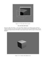
Fig. PMD.23
Adding a mirror modifier in Blender is just like adding a Subsurf modifier: click the "Add
Modifier" button on the Modifiers panel of the Edit buttons and choose "Mirror". The
mirrored half will appear as ghosted lines in Wireframe mode, but will be fully solid in Solid
mode.
Enabling the "Do Clipping" button in the Modifiers panel will prevent any vertices you
transform from crossing the center line of the mirror effect.
When you have finished symmetrical modeling, pressing the "Apply" button in the Modifiers
panel will make the mirrored half of the model into actual geometry that can be selected and
modified independently.
Loop Cut
In addition to the other subdivision controls that you have learned, the loop subdivide tool
allows you to quickly and uniformly subdivide all the edges that are within the same "loop".
In the illustration below, you can see the cut line looping around the eye, which will allow the
modeler to add crease lines. To initiate a Loop Cut, press Ctrl-R and move the cursor over the
model. While moving the cursor, you'll notice that when Blender detects groups of edges that
it can cut, a magenta line will appear to indicate the location of a possible loop cut. When the
magenta line indicates the loop that you would like to cut, press the LMB once to begin the
cut. Then, Blender will allow you to slide the cut back and forth between the outer edges by
moving the mouse. You can even increase or decrease the number of cuts made along the loop
by using the scroll wheel. When you have the cutting line positioned exactly as you like,
pressing the LMB will have Blender make the cuts. Pressing the RMB at any point in the
procedure cancels the cut.
Fig. PMD.24: A new loop is being cut around the eye on the right side of the image.
Edge Slide
Once you begin using the Loop Cut tool to add detail to your models, you may find that edge
loops become even more useful. For example: what if the cut that was made around the eye in
the previous illustration fell along the center of the edges, but you had really wanted it nearer
to the exterior loop? Instead of moving each edge individually, you can simply Alt-RMB
select the edge loop, then choose "Edge Slide" from the Ctrl-E Edge Specials menu in the 3D
view. This allows you to slide the edge back and forth between the two bounding loops. LMB
accepts the slide, while RMB cancels. This tool will actually allow you to slide any selectable
edge loop, regardless of what tools were used to create it.
Edge Loop Delete
One of the elements in the X-key delete menu we have not mentioned is the "Edge Loop"
option. With an edge loop selected, using this option from the X-key delete menu will remove
the edges, but join the faces on either side. The effect is as though an edge loop had never
been cut there. This is a great tool for cleanly reducing the polygon count of your meshes
once you have them looking the way you want.
Conclusion
In this introduction, you have seen the basic tools for polygon modeling in Blender and
learned a little about how you can begin to work with them. If you haven't already worked
through the tutorial section of this chapter, it's a good way to see this theory put into practice,
and to learn a few more tricks as well.
Best of luck,
Kevin Braun
Mesh Modeling Tutorial
By Roland Hess Based on the Blender Summer of Code tutorial by Michael Worcester
In the previous chapter, you learned how to manipulate objects in Blender. You've seen how
to move, scale and rotate objects, as well as some ways to set Blender to different modes.
But now we want you to actually edit the object itself. Blender has several modes for dealing
with objects, but the two most frequently used are Object Mode and Edit Mode. In Object
Mode you work with the object as a whole - you can move objects, scale them and rotate and
parent them. In Edit Mode you concentrate on one particular object, and make changes to the
mesh that gives the object its shape.
So, what's a mesh? I hear you asking. Usually, Blender (and computers in general) represents
3D objects by a set of vertices (or points) connected by edges. Three (or sometimes four)
vertices can form the boundaries of a "face". A face is just a part of a mesh that is "filled in",
and will look solid when rendered. Vertices and edges do not render, but faces do.
Here are some images to attempt to make this clearer.
Image:Dummy.png
Figure MMT.00: [no text]
In Edit Mode, you manipulate the object at the vertex level.
Figure MMT2.55: Where we'll be heading in this tutorial.
This model is what we hope to achieve in this tutorial. In theory, you could come close to
making this all in object mode, but what you need to learn is when and where to use the
different tools Blender has to offer. Knowing that this is the product of experience, doing this
tutorial will give you some idea of how to choose your tools.
Anyway, enough about theory. Let's get down to modeling. Start up Blender (or use Ctrl-X to
begin a new session if Blender is already running) and press the Z-key. The Z-key toggles
between shaded mode and wireframe mode. You can switch between these two modes
whenever you want to see how you're model is coming along. In this tutorial, some
screenshots will be in wireframe mode and some will be in solid mode. You don't have to be
there too, though. We tried to choose the best mode just to let you see what was going on in
the illustration.
RMB select the default cube in the center of the scene, then press the X-key and confirm its
deletion.
The first thing you are going to do is to create the basic shape of one of the pillars. You could
do this with a simple cube, but as the pattern on each side of the pillar is identical, you are
going to create one side, then duplicate it.
Use the spacebar to bring up the toolbox, then select the following menu items: Add, then
Mesh, then Cube. I know, you just deleted the default cube, but we want to get you familiar
with using the toolbox.
Figure MT2.A: The toolbox, about to add a cube.
You may remember from the previous chapter that when you add a new object, that object
begins its life in Edit mode. You should be able to see 4 yellow dots at the corners, which are
called vertices. A yellow vertex means that it is currently selected. Press the A-key and watch
all the vertices turn pink. (This is also the case for edges and faces.) To recap, just as the A-
key toggles select all/deselect all for objects, it does the same in Edit mode, only with
vertices.
Figure MT.04: The cube in Edit mode.
Selecting Vertices
There are several ways to select vertices in Blender.
- RMB. Just like object mode, clicking on (or near) a vertex with the RMB will select it.
Holding down Shift while RMB clicking will build a selection. RMB on an already selected
vertex will deselect.
- Border select. Press the B-key, then LMB drag over the area you want to select. Border
select is always additive, so using it will add to the selection set you already have.
- Circle select. Press the B-key twice, and the cursor turns into a circle. You are now in circle
select mode. You can "paint" a selection with this circle by LMB dragging. MMB dragging
deselects. The mouse's scroll wheel increases and decreases the size of the circle. RMB ends
circle select mode.
- Lasso select. Holding down Ctrl while LMB dragging lets you "lasso" vertices for selection.
As you draw around the vertices you would like to select, a dashed line is drawn to show
where you have dragged so far. Releasing the LMB completes the shape you have been
drawing, then selects any vertices that fall within it.
Using Numpad 7, view the cube from the top.
Now, select the four verts nearest the top of the screen. There's only two, you say? Remember
that for right now, you're looking straight down on the top of a three dimensional cube, and
can only see two vertices because the others are directly behind them. If you like, you can
rotate the view a bit by dragging with MMB just to make sure (or toggle in and out of
perspective mode with Numpad-5), then return to the top view with Numpad 7.
So, using any of the above selection modes, except for standard RMB, select the four vertices
(which will look like only two) nearest to the top of the screen. Press the X-key, then select
"Vertices" from the Erase menu that pops up.
Figure MMT2.01: The cube with the top vertices selected.
Just so you can see what you did, here's an off-axis view of the cube with those four vertices
removed. It's now just a square.
Figure MMT2.02: The plane that's left when you delete the vertices.
Use Numpad-1 to change to a front view. A-key to select all the vertices (or you can Shift-
RMB all four for practice), then press G-key to enter Grab mode. We would like you to move
the quad to be in the exact position as the next illustration:
Figure MMT2.03: The remaining quad with its lower left vertex at the origin.
Notice that the lower right vertex is exactly at the intersection of the red and blue axes (x and
z). In order to move the quad exactly onto that, hold down the Ctrl key while moving in Grab
mode. With the Ctrl key down, the movement snaps to a grid, allowing you to easily put the
lower left vert exactly on the origin.
Here's an alternate trick for doing precision movement. Undo (Ctrl-Z) the translation you just
performed. Now, press the G-key to enter Grab mode, followed by (and type exactly what is
inside the quotes) "x1". Then hit Enter. Now, type "gz1" and hit Enter. The quad should have
moved one full unit to the right, then one full unit up. Blender accepts numeric keyboard input
in transformation modes. Obviously, you won't use that trick all the time, but it's excellent, for
example, if you want to move something along a single axis for a specific distance, or to scale
something to exactly twice its original size.
You might have noticed in the original image that the faces of the pillars below the bridge are
symmetrical. This will allow you to take advantage of one of Blender's most powerful mesh
tools: modifiers.
Using Modifiers
In the Buttons window below the 3D view, use F9 to get to the Editing buttons, and find the
Modifiers panel.
MMT2.04: The modifiers panel before adding modifiers.
Click the "Add Modifier" button, then choose "Mirror" from the popup menu. Some new
controls will appear. You will also notice that in the 3D view, the quad has been mirrored
along the X axis. This mirrored copy is a "live" effect, and can be reconfigured at will in the
modifiers panel.
Tip:
Modifiers make on-the-fly changes and additions to
meshes.
Using a mirror modifier means that any changes you make on the original portion of the mesh
will be reflected in the mirrored portion. And, since the pillar you are trying to make is
symmetrical both left to right and top to bottom, you'll add a second mirror modifier.
Click "Add Modifier" again, and choose "Mirror". Another mirror modifier appears in the
Modifiers tab, below the first one. Nothing happens in the 3D view. This is because the
second modifier is set up exactly like the first, creating a second copy mirrored along the X
axis, overlapping the first. You want this copy to be top-to-bottom, so change the axis of the
second modifier by clicking its "Z" button. When you do that, you see the quad now mirrored
along two axes, like the next illustration.
Another way to create this modifier would be to press the "Copy" button on the original
mirror modifier, making a duplicate below the original that can be changed to suit your needs.
MMT2.05: Notice the ghosted items to the left of and below the main mesh.
Finally, turn on the "Do Clipping" option in both modifiers. This will prevent any vertices you
move from crossing the X or Z axes, which would cause overlapping meshes at the mirror
point. The option "clips" any transformation that crosses its axis. When you have the
modifiers set up properly, the panel should look like this:
Image:Dummy.png
MMT2.05.1: The Modifiers panel with both mirror modifiers in place.
Now, with all four vertices still selected, use the G-key again, and see how things function
with the modifiers in place. Moving the quad away from the mirrored axes does the same for
all four copies. Moving it toward the axes actually changes its dimensions as the "Do
Clipping" option keeps the vertices from crossing the axes. Move it around until it looks
something like the next illustration, then LMB to accept the transform.
MMT2.06: Try to move the quad around until it looks like this.
Subdivision
One way to begin adding detail to a mesh model is through subdivision. Subdivision is simply
dividing faces like your quad into smaller faces that take up the same space. Blender has
several tools for dividing faces and edges, and you'll use one of them now.
With all four vertices of the quad selected, press the W-key to bring up the Specials menu.
This menu contains a lot of common mesh modeling operations. In the menu, LMB on
"Subdivide Multi", and accept the default "Number of Cuts: 2" that appears. The quad is
divided twice in each direction, leaving you with something like this:
MMT2.07: This quad has been subdivided.
As was mentioned before, some screenshots, like the previous one, are in wireframe mode,
and may not match your screen. You can toggle between wireframe and solid modes by using
the Z-key.
We would like some of those faces to form the basis of a nice border for your pillar, but you
need to adjust them a bit first.
Working with Edges
Up until now, you've been working with vertices. It is also possible to work directly with
edges (the lines that connect vertices) or faces (the filled spaces defined by edges). On the 3D
header, click the Edge button, as shown in the illustration:
Image:Dummy.png
MMT2.08.01: These three buttons choose different select modes.
In the 3D view, the vertices disappear. You were working in Vertex mode before, but now
you are working in Edge mode. All the same selection tools (RMB, Border, Lasso, etc.) apply
to edges that applied to vertices and objects, but you get a few new and very useful tools as
well.
While holding down the Alt key, RMB on any edge in the quad. The entire line of edges
associated with the one you clicked is selected. This is called Edge Loop selection. Now,
Edge Loop select (Alt-RMB) one of the interior vertical edges.
Press Ctrl-E, and a menu titled "Edge Specials" appears. From that menu, LMB select "Edge
Slide". The edge loop you have selected enters a special kind of grab mode that allows you to
slide it between the edge loops on either side. As with any other transform mode, LMB
accepts the change and RMB cancels.
Using a combination of Alt-RMB select and the Edge Slide tool, try to select and move the
interior edges up and to the right so that your model looks like this:
MMT2.08: Try to get the subdivided edges to line up like this.
Now, you're going to subdivide the big face that's on the lower left of the quad. In fact, the
first thing you'll do is change it from a quad into two triangles. With the mouse over the 3D
view, press Ctrl-Tab, then select "Face" from the menu that pops up. The Ctrl-Tab menu is an
alternate way of changing the select mode between vertices, edges and faces. Notice that once
you are in Face select mode, all faces have a little point in their centers. This helps to
differentiate them from areas that might be bound by vertices and edges, but are not true
"filled in spaces" like a face.
RMB select the large face in the lower left, then press Ctrl-T to split the face into two triangle
faces. If the triangles in your model appear differently than the ones in the illustration (the
diagonal runs the other direction), use the Flip triangles command, Ctrl-F, to change it.
MMT2.10: The lower left face has been split into two triangle faces.
The Knife Tool
With the two triangle faces still selected, press the K-key to bring up the cutting tools. Select
"Knife (Exact)" from the menu. The Knife tool lets you draw directly on the screen by either
dragging with the LMB or by repeatedly LMB clicking for straight, point-to-point lines. The
lines that you draw will be used to cut any selected edges and divide any faces that they make
up. At any point during the process, you can click with the RMB to cancel.
After you've pressed the K-key and selected "Knife (Exact)", LMB drag to create a line that
looks something like this:
MMT2.10.5: The line your knife cut should follow.
When you have that, press the Enter key to accept the cut. Now that the cut is made, switch to
Edge select mode (with either Ctrl-Tab or on the 3D header), and using the Knife (Exact) tool,
make another similar cut, just inside the first.
MMT2.11: The mesh after accepting the knife cuts.
Pulling Vertices Into Line
This new set of cuts will form a second, interior border on your column. Right now, though,
the cuts you've made are kind of crooked. To fix that, you'll learn a technique that is so
frequently used it will become almost automatic to you eventually.
Go into Vertex select mode (Ctrl-Tab or 3D header), and select only the two rightmost of the
cuts you just made.
MMT2.12.1
Move the mouse cursor to the right of the model, but still within the 3D window. Now, press
the S-key for Scaling, and begin to move the mouse toward the model. The vertices will move
toward each other. As you move the mouse to the left, click the MMB one time. A horizontal
line appears. Clicking the MMB while moving the mouse during a transform constrains that
transformation along the axis nearest to the motion of the mouse. In this case, because you
were moving the mouse from side to side when the MMB was clicked, it constrained the
scaling transform along the X axis.
While still in the Scaling transform mode, hold down the Ctrl key. As you learned before,
holding down Ctrl during a transformation snaps the values to even intervals. Continue to
move the mouse toward the line between the vertices. When the mouse is very near to the
edge, it will become perfectly vertical and the readout on the 3D header will display "Scale:
0.0000 along the global X axis". When you see that, press the LMB to confirm the move.
That was just a very detailed explanation of what turns out to be a simple effect. The reason
we went into such detail is that this technique is an important tool that you will use again and
again in your modeling.
Tip:
To align selected vertices along a single axis, use the S-key,
MMB click to constrain the scale along a single axis, then
hold down Ctrl to snap to exact values. Reduce the scale to
0 and LMB.
If you would rather use the keyboard to do the same thing, you could select the vertices, then
press "sx0" and Enter.
Using this technique, straighten the three other edges that were created with the knife tool.
Remember that you will want to scale along the Z axis for the vertices whose connecting
edges are horizontal.
MMT2.12: Using the aligning technique, you should be able to arrive at this.
Depth Through Extrusion
Go into Face select mode and select the five faces that will form your borders. Using the
MMB, rotate the 3D view off-axis a bit, like the illustration, so you can get a better view of
the next step.
Figure MMT2.13: Select these five faces.
"The extrude tool is applied to a face or a group of faces. It creates a new face of the same
size and shape which is connected to each of the existing edges by a face. Thus, performing
the extrude operation on a square face would create a cube connected to the surface at the
location of the face." - Wikipedia entry for "Construction of Polygon Meshes"
If that went straight over your head, fear not! You shall learn by trying. Press the E-key and
select Region from the popup that appears. This will duplicate the selected part of the mesh
and connect the newly created section to the currently selected part. Blender automatically
puts you in translation mode, constrained to the direction perpendicular to the previously
selected face (in this case, that's along the Y axis). Translate (remember, you don't need to
press anything, you're already in the correct mode) until your model looks something like the
illustration.
Figure MMT2.14: The mesh after your first extrustion (shown in Solid mode).
Note: If you cancel the transformation with the RMB after doing an extrude, it's important to
know that the extrude itself is not undone. The new geometry that extrude creates remains in
the model, exactly on top of the original geometry that was selected. If you cancel out of the
transform portion of an extrude, make sure that you delete (X-key) the new geometry, which
should be the current selection.
From the illustration, and in your own model, you can now start to see the power of the mirror
modifiers. Whatever you do to the original instance of the mesh is mirrored in real time on the
duplicates, in this case creating two raised borders the whole way around the face of the pillar.
We'd like to make a nice ornament in the center of the pillar, so go to front view (Numpad-1).
Select the edges and use the K-key Knife (Exact) tool to make a cut as shown in the
illustration below.
Figure MMT2.15: The path of the Knife cut.
In face select mode, select the two innermost faces that were just created. With those faces
selected, you'll use the "Subdivide Multi" option from the W-key Specials menu. This time,
you'll increase the number of cuts to 3.
Figure MMT2.17: The two center triangle faces subdivided at multi level 3.
Back in vertex selection mode, RMB select every other vertex on the long diagonal edge of
the ornament. Using the G-key, followed by the Y-key to constrain the motion to the Y axis,
move those vertices outward from the face of the pillar.