Mechanism Design - Enumeration of Kinematic Structures According to Function P6 docx
Bạn đang xem bản rút gọn của tài liệu. Xem và tải ngay bản đầy đủ của tài liệu tại đây (1.06 MB, 30 trang )
Chapter 6
Classification of Mechanisms
6.1 Introduction
Using graph representation, mechanism structures can be conveniently represented
by graphs. The classification problem can be transformed into an enumeration of
nonisomorphic graphs for a prescribed number of degrees of freedom, number of
loops, number of vertices, and number of edges.
The degrees of freedom of a mechanism are governed by Equation (4.3). The
number of loops, number of links, and number of joints in a mechanism are re-
lated by Euler’s equation, Equation (4.5). The loop mobility criterion is given by
Equation (4.7). Since we are primarily interested in nonfractionated closed-loop
mechanisms, the vertex degree in the corresponding graphs should be at least equal
to two and not more than the total number of loops; that is, Equation (4.10) should
be satisfied. Furthermore, there should be no articulation points or bridges, and the
mechanism should not contain any partially locked kinematic chain as a subchain.
In this chapter, we classify mechanisms in accordance with the type of motion
followed by the number of degrees of freedom, the number of loops, the number of
links, the number of joints, and the vertex degree listing. The general procedure for
enumeration and classification of mechanisms is as follows. Given the number of
degrees of freedom, F , and the number of independent loops, L,
1. Solve Equations (4.3), (4.5), and (4.7) for the number of links and the number
of joints.
2. Solve Equations (4.12) and (4.13) for various link assortments, n
2
,n
3
,n
4
,
3. Identify feasible graphs and their corresponding contracted graphs from the
atlases of graphs listed in Appendices C and B or any other available resources
such as Read and Wilson [14].
4. Label the edges of each feasible graph with a given set of desired joint types.
This problem may be regarded as a partition of the edges into several parts.
Each part represents one type of joint. Two permutations are said to be equiv-
alent, if their corresponding labeled graphs are isomorphic. Therefore, we
© 2001 by CRC Press LLC
need to find the number of nonequivalent permutation sequences. For sim-
ple kinematic chains, the enumeration of labeled graphs can be accomplished
by inspection. For more complicated kinematic chains, a computer algorithm
employing partitioning and combinatorial schemes may be needed.
5. Identify the fixed, input, and output links as needed.
6. Check for mechanism isomorphisms and evaluate functional feasibility.
In the following, we illustrate the above procedure with several examples in order
of increasing complexity.
6.2 Planar Mechanisms
First, we study planar mechanisms. We shall limit the investigation to the following
types of joint: revolute (R), prismatic (P ), gear pair (G), and cam pair (C
p
). The
pin-in-slot joint can be replaced by prismatic and revolute joints with an intermediate
link. Both revolute and prismatic joints are one-dof joints, while gear and cam pairs
are two-dof joints. A mechanism is called a linkage if it is made up of only lower
pairs; that is, R and P joints. It is called a geared mechanism if it contains gear pairs,
a cam mechanism if it contains cam pairs, and a gear-cam mechanism if it contains
both gear and cam pairs.
6.2.1 Planar Linkages
Since revolute and prismatic joints are one-dof joints, the total joint degrees of
freedom in a planar linkage is equal to the number of joints; that is,
j
i=1
f
i
= j. (6.1)
Substituting λ = 3 and Equation (6.1) into Equations (4.3) and (4.7) yields
F = 3n − 2j − 3 , (6.2)
j = F + 3L. (6.3)
Eliminating j between Equations (4.5) and (6.3) gives
n = F + 2L + 1 . (6.4)
Equations (6.3) and (6.4) imply that given the number of degrees of freedom, each
time we increase the number of loops by one, it is necessary to increase the number
of links by two and the number of joints by three.
© 2001 by CRC Press LLC
Solving Equations (6.4) for L and then substituting the resulting expression into
Equation (4.10), we obtain
n − F + 1
2
≥ d
i
≥ 2 . (6.5)
In particular, for planar one-dof linkages, Equation (6.5) further reduces to
n
2
≥ d
i
≥ 2 .
Since we are interested in mechanisms with positive mobility, only those kinematic
chains that satisfy Equations (6.3) and (6.4) are said to be feasible. Furthermore, those
kinematic chains with partially locked subchains such as thethree- and five-link chains
shown in Figure 4.14 should be excluded from consideration.
We note that if a link has only two prismatic joints, they should not be parallel
otherwise the link will possess a passive degree of freedom. Except for the three-link
wedge shown in Figure 6.1, two links, each containing two prismatic joints, cannot
FIGURE 6.1
A three-link wedge.
be connected to each other. In general, there are no three-link planar mechanisms
that are composed exclusively of revolute and prismatic joints. The three-link wedge
mechanism shown in Figure 6.1 is an exception. Every link in the three-link wedge
mechanism performs planar translation without rotation. Hence, the motion param-
eter is equal to 2, i.e., λ = 2.
Planar One-dof Linkages
For planar one-dof linkages, Franke [4] showed that the number of nonisomorphic
kinematic structures having three independent loops is sixteen. Woo [28] showed
© 2001 by CRC Press LLC
that there are 230 nonisomorphic kinematic structures with four independent loops.
Table 6.1 summarizes the number of solutions for planar one-dof linkages with up to
four independent loops. In Table 6.1, the classification is made in accordance with the
number of independent loops followed by the number of links and then the various
link assortments.
Table 6.1 Classification of Planar One-dof Linkages.
Class No. of Total
Lnjn
2
n
3
n
4
n
5
Solutions Number
1 444000 1 1
2 674200 2 2
3 8104400 9 16
5210 5
6020 2
4 10 13 4 6 0 0 50 230
5410 95
6301 15
6220 57
7111 8
7030 3
8002 2
Four-Bar Linkages. For F = 1 and L = 1, Equations (6.3) and (6.4) give
n = j = 4. An examination of the atlas of graphs listed in Appendix C reveals
that there is only one (4, 4) graph with one independent loop. The corresponding
kinematic chain is given in Table D.1, Appendix D. Hence, the number of joints is
equal to the number of links and all the links are necessarily binary. Labeling the four
edges of the (4, 4) graph with as many combinations of R and P joints as possible
yields the following feasible kinematic chains:
RRRR, RRRP, RRPP , and RP RP .
Note that we have excluded the RPPP chain as a feasible solution, because it has
two adjacent links with only sliding pairs.
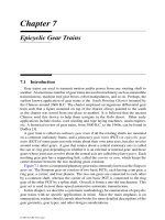
By assigning various links as the fixed link, we obtain seven basic four-bar mecha-
nisms as shown in Figure 6.2 [6]. These mechanisms can often be found in the heart
of industrial machinery. Note that we have essentially enumerated the kinematic
chains as combinations of four objects. Then we perform the kinematic inversion by
alternating the fixed link to obtain different mechanisms. Finally, we note that for a
given application, the input and output links should also be identified.
As shown in Figure 6.2, structure number 1 is the well-known planar four-bar
linkage. A four-bar linkage can be designed as a drag-link, crank-and-rocker, double-
rocker, or a change-point mechanism depending on the link length ratios [5, 7, 11,
20, 21]. Each of the number 2 and 3 structures contains one prismatic joint. In
© 2001 by CRC Press LLC
FIGURE 6.2
Seven basic four-bar linkages.
© 2001 by CRC Press LLC
sketching a prismatic joint, we can arbitrarily choose one link as the sliding block and
the other as the slotted guide. For this reason, structure number 2 can be sketched
into a turning-block linkage or a swinging-block linkage, depending on the choice of
pair representation. The turning-block linkage is often used to transform a constant
rotational speed of the crankshaft, link 1, into a nonuniform rotational speed or cyclic
oscillation of the follower, link 3. The swinging-block linkage can be designed
as an oscillating-cylinder engine mechanism as shown in Figure 6.3b. Structure
number 3 is the well-known crank-and-slider mechanism, which can be used as an
engine or compressor mechanism as shown in Figure 6.3a. Structure number 4 is
known as the Scotch yoke mechanism, which has been developed as a compressor
in an automotive air conditioning system. Structure number 5 is called the Cardanic
motion mechanism. Any point on link 2 of the Cardanic motion mechanism traces an
elliptical curve. In particular, the midpoint of link 2 generates a circular path centered
about the point defined by the intersection of the two prismatic joint axes.
FIGURE 6.3
Two engine mechanisms.
The sketching of a mechanism depends on the experience and skill of a designer.
This is best illustrated in structure number 6 (see Figure 6.2). A straightforward
sketch yields the inverse Cardanic motion mechanism. However, it would be difficult
to conceive the Oldham coupling, if we are not aware of the design to begin with. In
this regard, creativity and ingenuity play an important role. The Oldham coupling
is used as a constant velocity coupling to allow for small misalignment between two
parallel shafts. Because of the kinematic inversion, the center point of link 4 revolves
in a circular path at twice the input shaft frequency. Two counterrotating Oldham
couplings can be arranged side by side at the midplane of an in-line four-cylinder
engine to generate a second harmonic balancing force ([22], [23], [27]). Two such
couplings can also be arranged along an axis parallel to the crankshaft of a 90
◦
V-6
engine to generate primary and secondary rotating couples ([25], [26]). Similarly, by
© 2001 by CRC Press LLC
enlarging the two intermediate revolute joints of a drag-link mechanism, a generalized
Oldham coupling is obtained [8].
Six-Bar Linkages. For F = 1 and L = 2, Equations (6.3) and (6.4) yield n = 6
and j = 7. Hence, planar one-dof linkages with two independent loops contain six
links and seven joints. An examination of the atlas of graphs listed in Appendix C
reveals that there are three (6, 7) graphs. Excluding the (6, 7)(a) graph, which con-
tains a three-vertex loop as a subgraph, we obtain two unlabeled graphs as shown in
Table D.2, Appendix D. Also shown in the table are the vertex degree listing, the cor-
responding contracted graph, and typical structure representations of the kinematic
chains.
The first kinematic structure, listed in Table D.2, Appendix D, is known as the
Watt chain and the second the Stephenson chain. Each of the seven joints in these
kinematic chains can be assigned as a revolute or prismatic joint. Furthermore, any
of the six links can be chosen as the fixed link. The search for all feasible six-link
mechanisms becomes a more complicated task. However, for certain applications,
we might prefer one type of joint over the other. Then the task can be reduced to a
more manageable size. For example, if we limit ourselves to those mechanisms with
all revolute joints and ground-connected input and output links, then the number of
feasible six-bar linkages reduces to five as shown in Figure 6.4. The logic behind the
choice of fixed, input, and output link for the mechanisms shown in Figure 6.4 is as
follows.
Excluding the external loop, the Watt chain consists of two four-bar loops with
two common links and one common joint. To construct a mechanism with ground-
connected input and output links, one of the two ternary links must be grounded.
Any other choice of the fixed link will lead to one active four-bar loop, whereas the
other four-bar loop functions as an idler loop. Since the idler loop carries no loads,
the resulting mechanism is equivalent to a four-bar linkage. Once the fixed link is
chosen, the input and output links must be located on two different loops. Due to
symmetry, there is one such choice. Hence, there is only one possible arrangement
of the fixed, input, and output links.
The Stephenson chain consists of one four-bar loop and one five-bar loop with
three common links and two common joints. The two binary links in the four-bar
loop cannot be chosen as the fixed link. Otherwise, it will lead to one active four-bar
loop and one passive five-bar loop. Any other links can be chosen as the fixed link.
In addition, when one of the two ternary links is chosen as the fixed link, the input
and output links cannot be simultaneously located on the four-bar loop.
Figure 6.5b shows a six-bar linkage designed as a quick-return shaper mechanism.
The output link 6, which carries a cutting tool, slides back and forth in a fixed guide
designated as link 1. The input link 2 rotates about a fixed pivot A. The turning
block 3, which slides with respect to an oscillating arm 4, is connected to the input
crank by a turning pair at point C. The arm 4 oscillates about a fixed pivot B.
The output link 6 is connected to the oscillating arm by a coupler link 5 with two
revolute joints. As can be clearly seen from the corresponding graph depicted in
Figure6.5a, theshapermechanismbelongstotheWattchainwithfiverevoluteandtwo
© 2001 by CRC Press LLC
FIGURE 6.4
Planar one-dof six-bar linkages with all revolute joints and ground-connected
input and output links.
© 2001 by CRC Press LLC
prismatic joints. As the input crank rotates, the quick return motion is achieved by the
turning-block linkage, links 1-2-3-4 as shown in the lower half of the mechanism.
Specifically, the ratio of the time period during which the working stroke takes place
to the time period required in returning 6 to its initial position to start the next cycle,
is equal to the ratio of the angles through which the input crank turns during these
respective motions. It can be shown that this ratio depends only on the two link lengths
AC and AB. The six-bar construction helps minimize the reaction force between the
output link and the fixed guide.
FIGURE 6.5
Shaper mechanism.
Figure 6.6b shows a six-bar linkage developed as a variable valve-timing (VVT)
device [1]. This mechanism is made up of two turning-block linkages connected
in series. The first turning block linkage consists of links 1, 2, 3, and 4, whereas
the second contains links 1, 4, 5, and 6. The two turning block linkages share two
common links, 1 and 4. Link 1 is the fixed link. Both the input link 2 and the output
link 6 rotate about a common stationary axis B. The intermediate member 4 rotates
about an axis A whose location can be altered with respect to the stationary axis B.
The other two revolute joints are designated as C and D. The input link 2 takes power
from an engine crankshaft by a 2:1 reduction drive. An overhead cam (not shown
in the figure) is attached to the output shaft 6. This arrangement converts a constant
time scale associated with the crankshaft rotation into a variable time scale associated
with valve lift. The change of valve timing is achieved by rotating pivot A about the
fixed pivot B. Figure 6.6a shows the corresponding graph representation. This is a
Watt chain with five revolute and two prismatic joints.
© 2001 by CRC Press LLC
FIGURE 6.6
Variable-valve-timing mechanism.
Eight-Bar Linkages. For F = 1 and L = 3, Equations (6.3) and (6.4) reduce to
n = 8 and j = 10. Hence, planar one-dof linkages with three independent loops
contain eight links and ten joints. Eliminating those graphs containing the three- or
five-link structure as a subgraph from the atlas of (8, 10) graphs listed in Appendix C
results in 16 nonisomorphic unlabeled graphs as shown in Tables D.3 through D.6,
Appendix D. Each of the ten joints can be assigned as a revolute or prismatic joint and
any of the ten links can chosen as the fixed link. We see that the number of possible
combinations grows exponentially as the number of links increases.
Planar Two-dof Linkages
For planar two-dof linkages, Crossley [3] showed that there are 32 nonisomorphic
kinematic structures with 3 independent loops. Recently, Sohn and Freudenstein [17]
proved that the correct number is 35. Furthermore, they found that there are 726 non-
isomorphic structures with 4 independent loops. Table 6.2 summarizes the number of
solutions in terms of the number of independent loops, the number of links, and the
various link assortments for planar two-dof linkages with up to 4 independent loops.
Five-Bar Linkages. For F = 2 and L = 1, Equations (6.3) and (6.4) yield
n=j= 5. There is only one (5, 5) graph with one independent loop. The corre-
sponding kinematic structure is given in Table D.7, Appendix D. Labeling the five
edges of the graph with as many combinations of R and P joints as possible, yields
four nonisomorphic kinematic chains:
RRRRR, RRRRP, RRRPP , and RRP RP .
Here we have limited ourselves to those kinematic chains with no more than two
© 2001 by CRC Press LLC
Table 6.2 Classification of Planar Two-dof Linkages.
Class No. of Total
Lnjn
2
n
3
n
4
n
5
Solutions Number
1 555000 1 1
2 785200 3 3
3 9 11 5 4 0 0 19 35
6210 13
7020 3
4 11145600 726
6410
7301
7220
8111
8030
9002
prismatic joints. A mechanism that is made up of too many prismatic joints may
experience excessive friction.
Many mechanisms can be developed by assigning a different link as the fixed link.
However, if we prefer both input links to be ground connected, the output link must
necessarily be a floating link. Figure 6.7a shows a planar two-dof 5-R linkage in
which links 2 and 3 are assigned as the input links and link 4 as the output link.
The position of the end-point P on link 4 can be manipulated anywhere within a
2-dimensional workspace of the manipulator. A parallelogram linkage results when
the link lengths are sized according to the conditions: QA = BC, AB = CD, and
QD= 0 (i.e., pivots Q and D coincide). Furthermore, if link 1 is allowed to rotate
about a fixed axis as shown in Figure 6.7b, the mechanism becomes a fractionated
three-dof spatial manipulator.
Seven-Bar Linkages. For F = 2 and L = 2, Equations (6.3) and (6.4) reduce
to n = 7 and j = 8. Eliminating those graphs containing a three-link structure
as a subgraph from the atlas of (7, 8) graphs listed in Appendix C, results in three
nonisomorphic unlabeled graphs as shown in Table D.8, Appendix D.
Theoretically, any of the seven links can be assigned as the fixed link. We note
that, excluding the external loop, the first kinematic chain consists of a four- and a
five-bar loop; the second consists of two five-bar loops; and the third is made up of a
four- and a six-bar loop. Since a four-bar loop possesses only one degree of freedom,
none of the binary links in the loop can be chosen as the fixed link. Otherwise, it
would be impossible to arrange two ground-connected input links. Furthermore if
the output link is also to be connected to the ground, the fixed link must be a ternary
link. When one of the ternary links in the first or third kinematic chain is fixed,
due to the presence of a four-bar loop, a ground-connected output link is impossible.
In this regard, the second kinematic chain becomes the only feasible candidate to
© 2001 by CRC Press LLC
FIGURE 6.7
Two- and three-dof manipulators.
have ground-connected input and output links. Alternatively, the output link can be a
floating link. For example, Figure 6.8 shows a planar two-dof manipulator constructed
from the second kinematic chains given in Table D.8, Appendix D. Obviously, each
joint shown in Table D.8 can be a revolute or a prismatic joint.
Nine-Bar Linkages. For F = 2 and L = 3, Equations (6.3) and (6.4) reduce
to n = 9 and j = 11. Eliminating those graphs containing the three- or five-link
structure as a subgraph from the atlas of (9, 11) graphs listed in Appendix C leads to
35 nonisomorphic graphs as shown in Tables D.9 through D.14, Appendix D.
Planar Three-dof Linkages
For planar three-dof linkages, Sohn and Freudenstein [17] showed that there are 5
nonisomorphic kinematic structures with 2 independent loops and 74 with 3 indepen-
dent loops. Table 6.3 summarizes the number of solutions in terms of the number of
independent loops, the number of links, and the various link assortments for planar
three-dof linkages having up to four independent loops.
Planar three-dof linkages are not as well understood as their planar one- and two-
dof counterparts. For a single-loop mechanism, one of the actuators must be installed
on the moving links. In this regard, the mass of the floating actuator becomes the load
of the others. To reduce the inertia and to increase the stiffness, parallel kinematics
machines have been investigated recently. A parallel kinematics machine allows all
© 2001 by CRC Press LLC
FIGURE 6.8
Planar two-dof parallel manipulator.
actuators to be mounted on the ground. Hence, low inertia, high stiffness, and high
speed capabilities can be achieved.
Six-Bar Linkages. For F = 3 and L = 1, Equations (6.3) and (6.4) yield n =
j = 6. There is only one (6, 6) graph with one independent loop. The corresponding
kinematic structure is shown in Table D.15, Appendix D. One major disadvantage of
using this kinematic chain as a three-dof device is that one of the input links cannot
be ground connected. Hence, the mass of a floating actuator becomes the load of the
grounded actuators.
Eight-Bar Linkages. For F = 3 and L = 2, Equations (6.3) and (6.4) reduce
to n = 8 and j = 9. Eliminating those graphs containing the three-link structure
as a subgraph from the atlas of (8, 9) graphs listed in Appendix C, we obtain five
nonisomorphic graphs shown in Table D.15, Appendix D, where the joint type is not
assigned.
We note that if the input links are to be ground connected, one of the ternary links
must be selected as the fixed link. A careful examination of the kinematic structures
reveals that the first and fourth kinematic chains should be excluded from further
consideration due to the existence of a four-bar loop. The second kinematic chain
should also be excluded because none of its links possesses full three degrees-of-
freedom motion. Hence, the third and fifth kinematic chains are the only two feasible
solutions. For the fifth kinematic chain to function as a three-dof device, the floating
ternary link serves as the output link. For the third kinematic chain, the binary link
that lies on the six-bar loop and is immediately adjacent to the floating ternary link,
© 2001 by CRC Press LLC
Table 6.3 Classification of Planar Three-dof Linkages.
Class No. of Total
Lnjn
2
n
3
n
4
n
5
Solutions Number
1 666000 1 1
2 896200 5 5
3 10 12 6 4 0 0 43 74
7210 25
8020 6
4 12 15 6 6 0 0 1898
7410
8301
8220
9111
9030
10002
serves as the output link. Figure 6.9 shows a planar three-dof parallel manipulator
constructed from the fifth graph with all revolute joints.
FIGURE 6.9
Planar three-dof parallel manipulator.
Ten-Bar Linkages. For F = 3 and L = 3, Equations (6.3) and (6.4) give n = 10
and j = 12. Sohn and Freudenstein [17] showed that there are 74 such kinematic
chains — too many to list here. See Sohn [16] for the results.
© 2001 by CRC Press LLC
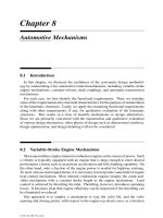
6.2.2 Planar Geared Mechanisms
Planar geared mechanisms are connected by revolute, R, prismatic, P , and gear,
G, pairs. Let j
i
denote the number of i-dof joints. By definition,
j = j
1
+ j
2
. (6.6)
Since the revolute and prismatic joints are one-dof joints and the gear pair is a two-dof
joint, the sum of the degrees of freedom in all joints can be written as
j
i=1
f
i
= j
1
+ 2j
2
. (6.7)
Eliminating j
1
between Equations (6.6) and (6.7), and substituting the resulting equa-
tion and λ = 3 into Equation (4.7) yields
j + j
2
= F + 3L. (6.8)
Hence, the number of joints and the number of links in a geared mechanism depend
not only on the degrees of freedom and the number of loops, but also on the number
of gear pairs. It has been shown that the number of gear pairs in a geared mechanism
cannot exceed the number of independent loops [13]; that is,
j
2
≤ L. (6.9)
Applying Equations (4.5), (6.8), and (6.9), geared mechanisms can be enumer-
ated and classified according to the number of degrees of freedom, the number of
independent loops, and the number of links. Table 6.4 shows the possible joint com-
binations in terms of the number of independent loops and the number of links for
planar one-dof geared mechanisms having up to four independent loops.
We note that some of the mechanisms formed by the joint combinations listed in
Table 6.4 will lead to unlimited rotation of all links. We call these types of mecha-
nisms gear trains. Gear trains can be classified further into ordinary gear trains and
planetary gear trains. The structural characteristics and the enumeration of epicyclic
gear trains will be studied in more detail in the following chapter.
One Independent Loop
The only single-loop graph suitable for a geared mechanism is the (3, 3) graph
given in Appendix C. One of the three edges in the graph must be labeled as a gear
pair, whereas the other two can be a combination of revolute and prismatic joints; that
is, RR, RP ,orPP joint pairs. Making all combinations of the one-dof joint pairs
with a gear pair yields three feasible kinematic chains:
RRG, RP G, and PPG.
The PPGchain is judged to be impractical and is excluded from further consideration.
By performing kinematic inversion, we obtain five nonisomorphic mechanisms as
© 2001 by CRC Press LLC
Table 6.4 Classification of One-dof Geared
Mechanisms.
No. of No. of No. of No. of
Class Links Joints Gear Pairs Revolute Joints
Ln j j
2
j
1
13 3 1 2
24 5 2 3
56 1 5
35 7 3 4
68 2 6
79 1 8
46 9 4 5
710 3 7
811 2 9
912 1 11
shown in Figure 6.10. We note that grounding the carrier of the RRG chain results in
a simple gear set. On the other hand, the kinematic chain becomes a simple planetary
gear set when one of the gears is grounded. Similarly, the RPG chain produces a
simple rack-and-pinion motion, an involute motion, or an inverse rack-and-pinion
motion depending on which link is grounded. Obviously, it is also possible to replace
the gear pair shown in Figure 6.10 by a noncircular gear pair.
Two Independent Loops
An inspection of Table 6.4 reveals that both (4, 5) and (5, 6) graphs are suitable for
construction of one-dof geared mechanisms having two independent loops.
(4, 5) Geared Mechanisms. For the (4, 5) graph, there must be two gear pairs and
three one-dof joints. For the purpose of illustration, let us assume that only revolute
and gear pairs are used. Then, the problem becomes a determination of labeling
the edges with two G pairs and three R joints. This is equivalent to a 2-coloring
problem in graph theory. To prevent the creation of a partially locked kinematic
chain, at least one of the three edges in each triangular loop must be labeled as a
G-edge. For this simple case, however, the problem can be solved by inspection.
Figure 6.11 shows three nonisomorphic labeled graphs and the corresponding gear
trains sketched by using external gear pairs. Many different geared mechanisms can
be derived by performing the kinematic inversion. For example, if link 1 of the first
geared mechanism shown in Figure 6.11 is chosen as the fixed link, the resulting
mechanism is an ordinary gear train. However, if link 4 is chosen as the fixed link,
the mechanism becomes a planetary gear train.
Note that if we allow the gear pairs to assume various combinations of internal
and external meshes, the number of possible geared mechanisms will be more than
tripled.
© 2001 by CRC Press LLC
FIGURE 6.10
Geared three-link mechanisms.
© 2001 by CRC Press LLC
FIGURE 6.11
Four-link gear trains.
© 2001 by CRC Press LLC
(5, 6) Geared Mechanisms. Next, we consider the (5, 6)-a graph listed in Ap-
pendix C. As can be seen from Table 6.4, there must be one gear pair, whereas the
remaining joints can be revolute or prismatic. To prevent the formation of a partially
locked structure, one of the joints in the three-link loop must be a gear pair. Assuming
that only a revolute pair is employed for the one-dof joints, there exist two noniso-
morphic labeled graphs as shown in Figure 6.12. The first kinematic chain shown
in Figure 6.12 consists of a simple gear pair and a four-bar linkage. The second
kinematic chain shown in Figure 6.12 is the well-known geared five-bar mechanism.
FIGURE 6.12
Geared five-bar chains.
6.2.3 Planar Cam Mechanisms
The enumeration of cam mechanisms is similar to that of geared mechanisms.
Since the degrees of freedom associated with a cam pair is identical to that of a gear
pair, we can practically replace any gear pair in a geared mechanism by a cam pair
without affecting its mobility. For three-link cam mechanisms, we also include the
PPC
p
labeling. Hence, we have
RRC
p
,RPC
p
, and PPC
p
.
Figure 6.13 shows seven nonisomorphic three-link cam mechanisms obtained by as-
signing different fixed links. In practice, a spring is incorporated in a cam
© 2001 by CRC Press LLC
FIGURE 6.13
Three-link cam mechanisms.
© 2001 by CRC Press LLC
mechanism to keep the cam pair in contact. Finally, we note that more complicated
cam mechanisms can be enumerated.
6.3 Spherical Mechanisms
The only available joint type for construction of spherical linkages is the revolute
joint. Furthermore, all joint axes must intersect at a common point called the spherical
center. Since the motion parameter, λ, of spherical mechanisms is identical to that
of planar mechanisms, the classification of spherical linkages can be accomplished
along the same line as planar bar-linkages. In the following, we simply point out a
few known spherical linkages.
The universal joint shown in Figure 1.11 is a spherical four-bar linkage. The four
revolute joint axes intersect at a common point, O. The universal joint is used for
connecting two intersecting nonparallel shafts.
Another type of spherical linkage is the three-dof orientation mechanism shown
in Figure 6.14 [9, 10]. The mechanism consists of a moving platform, link 7, that
is connected to a fixed base, link 0, by three kinematically identical limbs. All the
revolute joint axes intersect at a common point, O. The orientation of the moving
platform is controlled by actuating the three input links 1, 2, and 3.
FIGURE 6.14
Spherical parallel manipulator.
© 2001 by CRC Press LLC
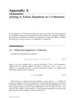
Most robotic wrists are geared spherical mechanisms [2, 15, 18, 19, 24]. For the
mechanism shown in Figure 6.15, link 1 is the base link; links 2, 5, and 6 are three
coaxial input links; and link 4 is the output link, which is called the end-effector. The
end-effector is free to rotate about three intersecting joint axes, a, b, and c. Rotations
of the three input links are transmitted to the end-effector by three bevel-gear pairs,
(5, 3), (6, 7), and (7, 4). Together, it forms a three-dof spherical wrist mechanism.
The enumeration of spherical wrist mechanisms will be discussed in more details in
a chapter to follow.
FIGURE 6.15
Geared spherical wrist mechanism.
6.4 Spatial Mechanisms
For spatial mechanisms, we limit ourselves to the following kinematic pairs: revo-
lute (R), prismatic (P ), helical (H ), cylindric (C), spherical (S), and plane (E) pairs.
These kinematic pairs can be grouped according to their joint degrees of freedom as
shown in Table 6.5.
Table 6.5 Classification of Kinematic Pairs.
Joint Degrees of Freedom Available Joint Types
1 R,P,H
2C
3S,E
Other more complicated kinematic pairs are excluded from the following discus-
sions. If such joints are considered, they can be replaced by a combination of two
© 2001 by CRC Press LLC
lower-pair joints with an intermediate link to achieve compactness and good surface
contact. For example, Figure 6.16a shows a washing machine agitator mechanism
that is made up of three links connected by a revolute, R, sphere-in-cylinder, S
c
,
and cylindric, C, joint. As the input link 2 rotates, the output link 3 will oscillate
and reciprocate simultaneously to generate a washing action. The sphere-in-cylinder
joint can be replaced by a revolute and a spherical joint with an intermediate link 4
as shown in Figure 6.16b.
FIGURE 6.16
Washing machine agitator mechanisms.
Under the above assumption, the total number of joints can be written as
j = j
1
+ j
2
+ j
3
. (6.10)
The total number of degrees of freedom in all joints is given by
j
i=1
f
i
= j
1
+ 2j
2
+ 3j
3
. (6.11)
Substituting λ = 6 and Equation (6.11) into Equation (4.7) yields
j
1
+ 2j
2
+ 3j
3
= F + 6L. (6.12)
Equation (6.12) is useful for determination of the number of joints for each type of
kinematic pair. Given the number of degrees of freedom, the number of loops, and
the number of links, we solve Equations (4.5) for the number of joints, and then
Equations (6.10) and (6.12) for all possible combinations of joint types.
© 2001 by CRC Press LLC
6.4.1 Spatial One-dof Mechanisms
For spatial one-dof mechanisms, we first solve Equation (4.5) for the number of
joints in terms of the number of independent loops and the number of links. Then,
we solve Equations (6.10) and (6.12) for all possible combinations of the joint types.
We do this by applying the nested-do loops algorithm described in Appendix A. The
results are summarized in Table 6.6. Note that we have restricted the number of
three-dof joints to one in single-loop chains and two in double-loop chains to avoid
the possibility of forming passive degrees of freedom.
Table 6.6 Classification of Spatial One-dof Mechanisms.
No. of No. of No. of No. of No. of
Class Type Links Joints 1-dof Joints 2-dof Joints 3-dof Joints
Lnjj
1
j
2
j
3
1 021 3 3 0 2 1
211 4 4 2 1 1
130 4 4 1 3 0
401 5 5 4 0 1
320 5 5 3 2 0
510 6 6 5 1 0
700 7 7 7 0 0
2 132 5 6 1 3 2
051 5 6 0 5 1
322 6 7 3 2 2
241 6 7 2 4 1
160 6 7 1 6 0
512 7 8 5 1 2
431 7 8 4 3 1
350 7 8 3 5 0
Each type listed in Table 6.6 is denoted by a three-digit number representing the
number of one-, two-, and three-dof joints, respectively [12]. For example, the
type 211 chain contains 2 one-dof, 1 two-dof, and 1 three-dof joints.
Since each joint of a given type can assume several different kinematic pairs, we
can further divide each type by the kind of joints incorporated in the kinematic chain.
Such a listing is called a kind. For example, the type 211 chain can be further clas-
sified into the following kinds: RRC S, RP CS , RHCS, PPCS, PHCS, HHCS,
RRCE , RPCE, RHCE, PPCE,PHCE, and HHCE. The above symbolic no-
tations can also be written as 2RCS,RP CS, RHCS,2PCS, etc. In what follows,
we limit the number of prismatic joints to no more than two since mechanisms having
more than two prismatic joints are not very practical.
The joints in each kind are used to label the edges of a graph. Two labelings are said
to be equivalent if their corresponding labeled graphs are isomorphic. Therefore, we
need to enumerate nonisomorphic labeled graphs of a given kind. For simple kine-
matic chains, the enumeration can be accomplished by inspection. For complicated
© 2001 by CRC Press LLC
kinematic chains, a computer algorithm employing partitioning and combinatorial
schemes is necessary.
Various mechanisms are obtained by selecting a different member of a kinematic
chain as the fixed link. This procedure is fairly straightforward. However, some of
the inverted mechanisms may be kinematically isomorphic to each other, whereas
others may be impractical for applications.
Single-Loop Mechanisms
For single-loop mechanisms, the number of joints is equal to the number of links
and all the links are necessarily binary. Furthermore, the joint degrees of freedom
should sum up to seven,
j
i=1
f
i
= 7 . (6.13)
Three-Link Chains. There exists only one type of three-link chain, type 021,
which can be classified into two kinds: CCS and CCE. Note that in constructing a
link with two cylindric joints, the two joint axes should not be parallel to each other,
otherwise a passive degree of freedom will be introduced. Similarly, in constructing
a pair of C–E joints, the axis of the cylindric joint should not be parallel to the plane
of the E pair. Lastly, we note that a mechanism having an input link connected to the
ground by a cylindric or spherical joint is not practical, since it is difficult to control
the motion of such a joint. Therefore, spatial three-link chains are not very practical.
Four-Link Chains. There are two types of four-link chains: types 211 and 130.
Type 211 can be classified into 12 kinds: RRCS , RP CS , RHCS, PP CS,P H CS,
HHCS, RRC E, RP CE , RHCE, PPCE, PHCE, and HHCE; whereas type 130
can be classified into three kinds: RCCC, PCCC, and H CCC. Making all possible
permutations of the joints yields 33 nonisomorphic labeled graphs of four-link chains
as shown in Table E.1, Appendix E.
Five-Link Chains. There are two types of five-link chains: types 401 and 320.
To further simplify the problem, let the helical joint be excluded from considera-
tion. Then, type 401 can be classified into six kinds: RRRRS , RRRP S, RRPPS,
RRRRE, RRRP E, and RRPPE; whereas type 320 can be classified into three
kinds: RRRCC, RRPCC, and RPPCC. Table E.2 in Appendix E shows 24 non-
isomorphic labeled graphs of five-link chains.
Six-Link Chains. There exists only one type of six-link chain: type 510. Ex-
cluding the helical joint, this type of kinematic chain can be classified into three
kinds: RRRRRC,RRRRPC, and RRRPPC. Table E.3 in Appendix E shows ten
nonisomorphic labeled graphs of six-link chains.
Seven-Link Chains. There exists only one type of seven-link chain: type 700.
Excluding the helical joint, this type of kinematic chain can be classified into three
© 2001 by CRC Press LLC