Text Book of Machine Design P28 pdf
Bạn đang xem bản rút gọn của tài liệu. Xem và tải ngay bản đầy đủ của tài liệu tại đây (761.07 KB, 45 trang )
Spur Gears
1021
1. Introduction.
2. Friction Wheels.
3. Advantages and
Disadvantages of Gear Drives.
4. Classification of Gears.
5. Terms used in Gears.
6. Condition for Constant
Velocity Ratio of Gears–Law of
Gearing.
7. Forms of Teeth.
8. Cycloidal Teeth.
9. Involute Teeth.
10. Comparison Between Involute
and Cycloidal Gears.
11. Systems of Gear Teeth.
12. Standard Proportions of Gear
Systems.
13. Interference in Involute Gears.
14. Minimum Number of Teeth on
the Pinion in order to Avoid
Interference.
15. Gear Materials.
16. Design Considerations for a
Gear Drive.
17. Beam Strength of Gear Teeth-
Lewis Equation.
18. Permissible Working Stress for
Gear Teeth in Lewis Equation.
19. Dynamic Tooth Load.
20. Static Tooth Load.
21. Wear Tooth Load.
22. Causes of Gear Tooth Failure.
23. Design Procedure for Spur
Gears.
24. Spur Gear Construction.
25. Design of Shaft for Spur Gears.
26. Design of Arms for Spur Gears.
28
C
H
A
P
T
E
R
28.128.1
28.128.1
28.1
IntrIntr
IntrIntr
Intr
oductionoduction
oductionoduction
oduction
We have discussed earlier that the slipping of a belt or
rope is a common phenomenon, in the transmission of
motion or power between two shafts. The effect of slipping
is to reduce the velocity ratio of the system. In precision
machines, in which a definite velocity ratio is of importance
(as in watch mechanism), the only positive drive is by gears
or toothed wheels. A gear drive is also provided, when
the distance between the driver and the follower is very
small.
28.228.2
28.228.2
28.2
Friction WheelsFriction Wheels
Friction WheelsFriction Wheels
Friction Wheels
The motion and power transmitted by gears is
kinematically equivalent to that transmitted by frictional
wheels or discs. In order to understand how the motion can
be transmitted by two toothed wheels, consider two plain
circular wheels A and B mounted on shafts. The wheels have
sufficient rough surfaces and press against each other as
shown in Fig. 28.1.
CONTENTS
CONTENTS
CONTENTS
CONTENTS
1022
n
A Textbook of Machine Design
* We know that frictional resistance, F = µ . R
N
where µ = Coefficient of friction between the rubbing surfaces of the two wheels, and
R
N
= Normal reaction between the two rubbing surfaces.
Fig. 28.1. Friction wheels. Fig. 28.2. Gear or toothed wheel.
Let the wheel A is keyed to the rotating shaft and the wheel B to the shaft to be rotated. A little
consideration will show that when the wheel A is rotated by a rotating shaft, it will rotate the wheel B
in the opposite direction as shown in Fig. 28.1. The wheel B will be rotated by the wheel A so long as
the tangential force exerted by the wheel A does not exceed the maximum frictional resistance between
the two wheels. But when the tangential force (P) exceeds the *frictional resistance (F), slipping will
take place between the two wheels.
In order to avoid the slipping, a number of projections (called teeth) as shown in Fig. 28.2 are
provided on the periphery of the wheel A which will fit into the corresponding recesses on the periphery
of the wheel B. A friction wheel with the teeth cut on it is known as gear or toothed wheel. The usuall
connection to show the toothed wheels is by their pitch circles.
Note : Kinematically, the friction wheels running without slip and toothed gearing are identical. But due to the
possibility of slipping of wheels, the friction wheels can only be
used for transmission of small powers.
28.328.3
28.328.3
28.3
Advantages and Disadvantages ofAdvantages and Disadvantages of
Advantages and Disadvantages ofAdvantages and Disadvantages of
Advantages and Disadvantages of
Gear DrivesGear Drives
Gear DrivesGear Drives
Gear Drives
The following are the advantages and disadvantages
of the gear drive as compared to other drives, i.e. belt, rope
and chain drives :
Advantages
1. It transmits exact velocity ratio.
2. It may be used to transmit large power.
3. It may be used for small centre distances of shafts.
4. It has high efficiency.
5. It has reliable service.
6. It has compact layout.
Disadvantages
1. Since the manufacture of gears require special
tools and equipment, therefore it is costlier than
other drives.
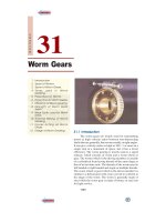
In bicycle gears are used to transmit
motion. Mechanical advantage can
be changed by changing gears.
Spur Gears
n
1023
2. The error in cutting teeth may cause vibrations and noise during operation.
3. It requires suitable lubricant and reliable method of applying it, for the proper operation of
gear drives.
28.428.4
28.428.4
28.4
Classification of GearsClassification of Gears
Classification of GearsClassification of Gears
Classification of Gears
The gears or toothed wheels may be classified as follows :
1. According to the position of axes of the shafts. The axes of the two shafts between which
the motion is to be transmitted, may be
(a) Parallel, (b) Intersecting, and (c) Non-intersecting and non-parallel.
The two parallel and co-planar shafts connected by the gears is shown in Fig. 28.2. These gears
are called spur gears and the arrangement is known as spur gearing. These gears have teeth parallel
to the axis of the wheel as shown in Fig. 28.2. Another name given to the spur gearing is helical
gearing, in which the teeth are inclined to the axis. The single and double helical gears connecting
parallel shafts are shown in Fig. 28.3 (a) and (b) respectively. The object of the double helical gear is
to balance out the end thrusts that are induced in single helical gears when transmitting load. The
double helical gears are known as herringbone gears. A pair of spur gears are kinematically equivalent
to a pair of cylindrical discs, keyed to a parallel shaft having line contact.
The two non-parallel or intersecting, but coplaner shafts connected by gears is shown in
Fig. 28.3 (c). These gears are called bevel gears and the arrangement is known as bevel gearing.
The bevel gears, like spur gears may also have their teeth inclined to the face of the bevel, in
which case they are known as helical bevel gears.
Fig. 28.3
The two non-intersecting and non-parallel i.e. non-coplanar shafts connected by gears is shown
in Fig. 28.3 (d). These gears are called skew bevel gears or spiral gears and the arrangement is
known as skew bevel gearing or spiral gearing. This type of gearing also have a line contact, the
rotation of which about the axes generates the two pitch surfaces known as hyperboloids.
Notes : (i) When equal bevel gears (having equal teeth) connect two shafts whose axes are mutually perpendicu-
lar, then the bevel gears are known as mitres.
(ii) A hyperboloid is the solid formed by revolving a straight line about an axis (not in the same plane),
such that every point on the line remains at a constant distance from the axis.
(iii) The worm gearing is essentially a form of spiral gearing in which the shafts are usually at right angles.
2. According to the peripheral velocity of the gears. The gears, according to the peripheral
velocity of the gears, may be classified as :
(a) Low velocity, (b) Medium velocity, and (c) High velocity.
1024
n
A Textbook of Machine Design
* A straight line may also be defined as a wheel of infinite radius.
Fig. 28.5. Rack and pinion.
The gears having velocity less than 3 m/s are termed as low velocity gears and gears having
velocity between 3 and 15 m / s are known as medium velocity gears. If the velocity of gears is more
than 15 m / s, then these are called high speed gears.
3. According to the type of gearing. The gears, according to the type of gearing, may be
classified as :
(a) External gearing, (b) Internal gearing, and (c) Rack and pinion.
Fig. 28.4
In external gearing, the gears of the two shafts mesh externally with each other as shown in
Fig. 28.4 (a). The larger of these two wheels is called spur wheel or gear and the smaller wheel is
called pinion. In an external gearing, the motion of the two wheels is always unlike, as shown in
Fig. 28.4 (a).
In internal gearing, the gears of the two shafts mesh internally with each other as shown in Fig.
28.4 (b). The larger of these two wheels is called annular wheel and the smaller wheel is called
pinion. In an internal gearing, the motion of the wheels is always like as shown in Fig. 28.4 (b).
Sometimes, the gear of a shaft meshes externally and
internally with the gears in a *straight line, as shown in Fig.
28.5. Such a type of gear is called rack and pinion. The
straight line gear is called rack and the circular wheel is
called pinion. A little consideration will show that with the
help of a rack and pinion, we can convert linear motion into
rotary motion and vice-versa as shown in Fig. 28.5.
4. According to the position of teeth on the gear
surface. The teeth on the gear surface may be
(a) Straight, (b) Inclined, and (c) Curved.
We have discussed earlier that the spur gears have
straight teeth whereas helical gears have their teeth inclined
to the wheel rim. In case of spiral gears, the teeth are curved
over the rim surface.
28.528.5
28.528.5
28.5
TT
TT
T
erer
erer
er
ms used in Gearms used in Gear
ms used in Gearms used in Gear
ms used in Gear
ss
ss
s
The following terms, which will be mostly used in this chapter, should be clearly understood at
this stage. These terms are illustrated in Fig. 28.6.
1. Pitch circle. It is an imaginary circle which by pure rolling action, would give the same
motion as the actual gear.
Spur Gears
n
1025
2. Pitch circle diameter. It is the diameter of the pitch circle. The size of the gear is usually
specified by the pitch circle diameter. It is also called as pitch diameter.
3. Pitch point. It is a common point of contact between two pitch circles.
4. Pitch surface. It is the surface of the rolling discs which the meshing gears have replaced at
the pitch circle.
5. Pressure angle or angle of obliquity. It is the angle between the common normal to two gear
teeth at the point of contact and the common tangent at the pitch point. It is usually denoted by φ. The
standard pressure angles are
1
2
14 /
°
and 20°.
6. Addendum. It is the radial distance of a tooth from the pitch circle to the top of the tooth.
7. Dedendum. It is the radial distance of a tooth from the pitch circle to the bottom of the tooth.
8. Addendum circle. It is the circle drawn through the top of the teeth and is concentric with the
pitch circle.
9. Dedendum circle. It is the circle drawn through the bottom of the teeth. It is also called root
circle.
Note : Root circle diameter = Pitch circle diameter × cos φ, where φ is the pressure angle.
10. Circular pitch. It is the distance measured on the circumference of the pitch circle from
a point of one tooth to the corresponding point on the next tooth. It is usually denoted by p
c
.
Mathematically,
Circular pitch, p
c
= π D/T
where D = Diameter of the pitch circle, and
T = Number of teeth on the wheel.
A little consideration will show that the two gears will mesh together correctly, if the two wheels
have the same circular pitch.
Note : If D
1
and D
2
are the diameters of the two meshing gears having the teeth T
1
and T
2
respectively; then for
them to mesh correctly,
p
c
=
12
12
DD
TT
ππ
=
or
11
22
DT
DT
=
Fig. 28.6. Terms used in gears.
1026
n
A Textbook of Machine Design
11. Diametral pitch. It is the ratio of number of teeth to the pitch circle diameter in millimetres.
It denoted by P
d
. Mathematically,
Diametral pitch, p
d
=
c
T
Dp
π
=
π
=
∵
c
D
p
T
where T = Number of teeth, and
D = Pitch circle diameter.
12. Module. It is the ratio of the pitch circle diameter in millimetres to the number of teeth. It is
usually denoted by m. Mathematically,
Module, m = D / T
Note : The recommended series of modules in Indian Standard are 1, 1.25, 1.5, 2, 2.5, 3, 4, 5, 6, 8, 10, 12, 16,
20, 25, 32, 40 and 50.
The modules 1.125, 1.375, 1.75, 2.25, 2.75, 3.5, 4.5,5.5, 7, 9, 11, 14, 18, 22, 28, 36 and 45 are of second
choice.
13. Clearance. It is the radial distance from the top of the tooth to the bottom of the tooth, in a
meshing gear. A circle passing through the top of the meshing gear is known as clearance circle.
14. Total depth. It is the radial distance between the addendum and the dedendum circle of a
gear. It is equal to the sum of the addendum and dedendum.
15. Working depth. It is radial distance from the addendum circle to the clearance circle. It is
equal to the sum of the addendum of the two meshing gears.
16. Tooth thickness. It is the width of the tooth measured along the pitch circle.
17. Tooth space. It is the width of space between the two adjacent teeth measured along the
pitch circle.
18. Backlash. It is the difference between the tooth space and the tooth thickness, as measured
on the pitch circle.
Spur gears
Spur Gears
n
1027
19. Face of the tooth. It is surface of the tooth above the pitch surface.
20. Top land. It is the surface of the top of the tooth.
21. Flank of the tooth. It is the surface of the tooth below the pitch surface.
22. Face width. It is the width of the gear tooth measured parallel to its axis.
23. Profile. It is the curve formed by the face and flank of the tooth.
24. Fillet radius. It is the radius that connects the root circle to the profile of the tooth.
25. Path of contact. It is the path traced by the point of contact of two teeth from the beginning
to the end of engagement.
26. Length of the path of contact. It is the length of the common normal cut-off by the addendum
circles of the wheel and pinion.
27. Arc of contact. It is the path traced by a point on the pitch circle from the beginning to the
end of engagement of a given pair of teeth. The arc of contact consists of two parts, i.e.
(a) Arc of approach. It is the portion of the path of contact from the beginning of the engagement
to the pitch point.
(b) Arc of recess. It is the portion of the path of contact from the pitch point to the end of the
engagement of a pair of teeth.
Note : The ratio of the length of arc of contact to the circular pitch is known as contact ratio i.e. number of pairs
of teeth in contact.
28.628.6
28.628.6
28.6
Condition fCondition f
Condition fCondition f
Condition f
or Constant or Constant
or Constant or Constant
or Constant
VV
VV
V
elocity Raelocity Ra
elocity Raelocity Ra
elocity Ra
tio of Geartio of Gear
tio of Geartio of Gear
tio of Gear
s–Law of Gears–Law of Gear
s–Law of Gears–Law of Gear
s–Law of Gear
inging
inging
ing
Consider the portions of the two teeth, one on the wheel 1 (or pinion) and the other on the wheel
2, as shown by thick line curves in Fig. 28.7. Let the two teeth come in contact at point Q, and the
wheels rotate in the directions as shown in the figure.
Let TT be the common tangent and MN be the common normal to the curves at point of contact
Q. From the centres O
1
and O
2
, draw O
1
M and O
2
N perpendicular to MN. A little consideration will
show that the point Q moves in the direction QC, when considered as a point on wheel 1, and in the
direction QD when considered as a point on wheel 2.
Let v
1
and v
2
be the velocities of the point Q on the wheels 1 and 2 respectively. If the teeth are
to remain in contact, then the components of these velocities
along the common normal MN must be equal.
∴ v
1
cos α = v
2
cos β
or (ω
1
× O
1
Q) cos α =(ω
2
× O
2
Q) cos β
1
11
1
()
OM
OQ
OQ
ω×
=
2
22
2
()
ON
OQ
OQ
ω×
∴ω
1
.O
1
M = ω
2
. O
2
N
or
1
2
ω
ω
=
2
1
ON
OM
(i)
Also from similar triangles O
1
MP and O
2
NP,
2
1
ON
OM
=
2
1
OP
OP
(ii)
Combining equations (i) and (ii), we have
1
2
ω
ω
=
2
1
ON
OM
=
2
1
OP
OP
(iii)
We see that the angular velocity ratio is inversely
proportional to the ratio of the distance of P from the centres
Fig. 28.7. Law of gearing.
1028
n
A Textbook of Machine Design
O
1
and O
2
, or the common normal to the two surfaces at the point of contact Q intersects the line of
centres at point P which divides the centre distance inversely as the ratio of angular velocities.
Therefore, in order to have a constant
angular velocity ratio for all positions of the
wheels, P must be the fixed point (called pitch
point) for the two wheels. In other words, the
common normal at the point of contact
between a pair of teeth must always pass
through the pitch point. This is fundamental
condition which must be satisfied while
designing the profiles for the teeth of gear
wheels. It is also known as law of gearing.
Notes : 1. The above condition is fulfilled by teeth
of involute form, provided that the root circles from
which the profiles are generated are tangential to
the common normal.
2. If the shape of one tooth profile is arbitrary
chosen and another tooth is designed to satisfy the
above condition, then the second tooth is said to be
conjugate to the first. The conjugate teeth are not
in common use because of difficulty in manufacture and cost of production.
3. If D
1
and D
2
are pitch circle diameters of wheel 1 and 2 having teeth T
1
and T
2
respectively, then
velocity ratio,
1
2
ω
ω
=
222
111
OP D T
OP D T
==
Aircraft landing gear is especially designed to absorb shock and energy when an
aircraft lands, and then release gradually.
Gear trains inside a mechanical watch
Spur Gears
n
1029
28.728.7
28.728.7
28.7
ForFor
ForFor
For
ms of ms of
ms of ms of
ms of
TT
TT
T
eetheeth
eetheeth
eeth
We have discussed in Art. 28.6 (Note 2) that conjugate teeth are not in common use. Therefore,
in actual practice, following are the two types of teeth commonly used.
1. Cycloidal teeth ; and 2. Involute teeth.
We shall discuss both the above mentioned types of teeth in the following articles. Both these
forms of teeth satisfy the condition as explained in Art. 28.6.
28.828.8
28.828.8
28.8
CyCy
CyCy
Cy
cc
cc
c
loidal loidal
loidal loidal
loidal
TT
TT
T
eetheeth
eetheeth
eeth
A cycloid is the curve traced by a point on the circumference of a circle which rolls without
slipping on a fixed straight line. When a circle rolls without slipping on the outside of a fixed circle,
the curve traced by a point on the circumference of a circle is known as epicycloid. On the other hand,
if a circle rolls without slipping on the inside of a fixed circle, then the curve traced by a point on the
circumference of a circle is called hypocycloid.
Fig. 28.8. Construction of cycloidal teeth of a gear.
In Fig. 28.8 (a), the fixed line or pitch line of a rack is shown. When the circle C rolls without
slipping above the pitch line in the direction as indicated in Fig. 28.8 (a), then the point P on the circle
traces the epicycloid PA . This represents the face of the cycloidal tooth profile. When the circle D
rolls without slipping below the pitch line, then the point P on the circle D traces hypocycloid PB
which represents the flank of the cycloidal tooth. The profile BPA is one side of the cycloidal rack
tooth. Similarly, the two curves P' A' and P' B' forming the opposite side of the tooth profile are traced
by the point P' when the circles C and D roll in the opposite directions.
In the similar way, the cycloidal teeth of a gear may be constructed as shown in Fig. 28.8 (b).
The circle C is rolled without slipping on the outside of the pitch circle and the point P on the circle
C traces epicycloid PA , which represents the face of the cycloidal tooth. The circle D is rolled on the
inside of pitch circle and the point P on the circle D traces hypocycloid PB, which represents the flank
of the tooth profile. The profile BPA is one side of the cycloidal tooth. The opposite side of the tooth
is traced as explained above.
The construction of the two mating cycloidal teeth is shown in Fig. 28.9. A point on the circle D
will trace the flank of the tooth T
1
when circle D rolls without slipping on the inside of pitch circle of
wheel 1 and face of tooth T
2
when the circle D rolls without slipping on the outside of pitch circle of
wheel 2. Similarly, a point on the circle C will trace the face of tooth T
1
and flank of tooth T
2
. The
rolling circles C and D may have unequal diameters, but if several wheels are to be interchangeable,
they must have rolling circles of equal diameters.
1030
n
A Textbook of Machine Design
Fig. 28.9. Construction of two mating cycloidal teeth.
A little consideration will show that the common normal
XX at the point of contact between two cycloidal teeth always
passes through the pitch point, which is the fundamental con-
dition for a constant velocity ratio.
28.928.9
28.928.9
28.9
InIn
InIn
In
vv
vv
v
olute olute
olute olute
olute
TT
TT
T
eetheeth
eetheeth
eeth
An involute of a circle is a plane curve generated by a
point on a tangent, which rolls on the circle without slipping
or by a point on a taut string which is unwrapped from a reel
as shown in Fig. 28.10 (a). In connection with toothed wheels,
the circle is known as base circle. The involute is traced as
follows :
Let A be the starting point of the involute. The base circle
is divided into equal number of parts e.g. AP
1
, P
1
P
2
, P
2
P
3
etc.The tangents at P
1
, P
2
, P
3
etc., are drawn and the lenghts
P
1
A
1
, P
2
A
2
, P
3
A
3
equal to the arcs AP
1
, AP
2
and AP
3
are set
off. Joining the points A, A
1
, A
2
, A
3
etc., we obtain the involute
curve AR. A little consideration will show that at any instant
A
3
, the tangent A
3
T to the involute is perpendicular to P
3
A
3
and
P
3
A
3
is the normal to the involute. In other words, normal at
any point of an involute is a tangent to the circle.
Now, let O
1
and O
2
be the fixed centres of the two base
circles as shown in Fig. 28.10(b). Let the corresponding
involutes AB and A'B' be in contact at point Q. MQ and NQ are
normals to the involute at Q and are tangents to base circles.
Since the normal for an involute at a given point is the tangent
drawn from that point to the base circle, therefore the common
normal MN at Q is also the common tangent to the two base
circles. We see that the common normal MN intersects the line
of centres O
1
O
2
at the fixed point P (called pitch point).
Therefore the involute teeth satisfy the fundamental condition
of constant velocity ratio.
The clock built by Galelio
used gears.
Spur Gears
n
1031
From similar triangles O
2
NP and O
1
MP,
1
2
OM
ON
=
12
21
OP
OP
ω
=
ω
(i)
which determines the ratio of the radii of the two base circles. The radii of the base circles is given by
O
1
M = O
1
P cos φ, and O
2
N = O
2
P cos φ
where φ is the pressure angle or the angle of obliquity.
Also the centre distance between the base circles
=
1212
12
cos cos cos
OM ON OM O N
OP OP
+
+= + =
φφ φ
Fig. 28.10. Construction of involute teeth.
A little consideration will show, that if the centre distance is changed, then the radii of pitch
circles also changes. But their ratio remains unchanged, because it is equal to the ratio of the two radii
of the base circles [See equation (i)]. The common normal, at the point of contact, still passes through
the pitch point. As a result of this, the wheel continues to work correctly*. However, the pressure
angle increases with the increase in centre distance.
28.1028.10
28.1028.10
28.10
Comparison Between Involute and Cycloidal GearsComparison Between Involute and Cycloidal Gears
Comparison Between Involute and Cycloidal GearsComparison Between Involute and Cycloidal Gears
Comparison Between Involute and Cycloidal Gears
In actual practice, the involute gears are more commonly used as compared to cycloidal gears,
due to the following advantages :
Advantages of involute gears
Following are the advantages of involute gears :
1. The most important advantage of the involute gears is that the centre distance for a pair of
involute gears can be varied within limits without changing the velocity ratio. This is not true for
cycloidal gears which requires exact centre distance to be maintained.
2. In involute gears, the pressure angle, from the start of the engagement of teeth to the end of
the engagement, remains constant. It is necessary for smooth running and less wear of gears. But in
cycloidal gears, the pressure angle is maximum at the beginning of engagement, reduces to zero at
pitch point, starts increasing and again becomes maximum at the end of engagement. This results in
less smooth running of gears.
3. The face and flank of involute teeth are generated by a single curve whereas in cycloidal
gears, double curves (i.e. epicycloid and hypocycloid) are required for the face and flank respectively.
* It is not the case with cycloidal teeth.
1032
n
A Textbook of Machine Design
Thus the involute teeth are easy to manufacture than cycloidal teeth. In involute system, the basic rack
has straight teeth and the same can be cut with simple tools.
Note : The only disadvantage of the involute teeth is that the interference occurs (Refer Art. 28.13) with pinions
having smaller number of teeth. This may be avoided by altering the heights of addendum and dedendum of the
mating teeth or the angle of obliquity of the teeth.
Advantages of cycloidal gears
Following are the advantages of cycloidal gears :
1. Since the cycloidal teeth have wider flanks, therefore the cycloidal gears are stronger than
the involute gears for the same pitch. Due to this reason, the cycloidal teeth are preferred specially for
cast teeth.
2. In cycloidal gears, the contact takes place between a convex flank and concave surface,
whereas in involute gears, the convex surfaces are in contact. This condition results in less wear in
cycloidal gears as compared to involute gears. However the difference in wear is negligible.
3. In cycloidal gears, the interference does not occur at all. Though there are advantages of
cycloidal gears but they are outweighed by the greater simplicity and flexibility of the involute gears.
28.11 Systems of Gear 28.11 Systems of Gear
28.11 Systems of Gear 28.11 Systems of Gear
28.11 Systems of Gear
TT
TT
T
eetheeth
eetheeth
eeth
The following four systems of gear teeth are commonly used in practice.
1.
1
2
14 /
°
Composite system, 2.
1
2
14 /
°
Full depth involute system, 3. 20° Full depth involute
system, and 4. 20° Stub involute system.
The
1
2
14 /
°
composite system is used for general purpose gears. It is stronger but has no inter-
changeability. The tooth profile of this system has cycloidal curves at the top and bottom and involute
curve at the middle portion. The teeth are produced by formed milling cutters or hobs. The tooth
profile of the
1
2
14 /
°
full depth involute system was developed for use with gear hobs for spur and
helical gears.
The tooth profile of the 20° full depth involute system may be cut by hobs. The increase of the
pressure angle from
1
2
14 /
°
to 20° results in a stronger tooth, because the tooth acting as a beam is
wider at the base. The 20° stub involute system has a strong tooth to take heavy loads.
28.1228.12
28.1228.12
28.12
StandarStandar
StandarStandar
Standar
d Prd Pr
d Prd Pr
d Pr
oporopor
oporopor
opor
tions of Gear Systemstions of Gear Systems
tions of Gear Systemstions of Gear Systems
tions of Gear Systems
The following table shows the standard proportions in module (m) for the four gear systems as
discussed in the previous article.
TT
TT
T
aa
aa
a
ble 28.1.ble 28.1.
ble 28.1.ble 28.1.
ble 28.1.
Standar Standar
Standar Standar
Standar
d prd pr
d prd pr
d pr
oporopor
oporopor
opor
tions of gear systemstions of gear systems
tions of gear systemstions of gear systems
tions of gear systems
.
S. No. Particulars
°
1
2
14 /
composite or full 20° full depth 20° stub involute
depth involute system involute system system
1. Addendum 1m 1m 0.8 m
2. Dedendum 1.25 m 1.25 m 1 m
3. Working depth 2 m 2 m 1.60 m
4. Minimum total depth 2.25 m 2.25 m 1.80 m
5. Tooth thickness 1.5708 m 1.5708 m 1.5708 m
6. Minimum clearance 0.25 m 0.25 m 0.2 m
7. Fillet radius at root 0.4 m 0.4 m 0.4 m
Spur Gears
n
1033
28.1328.13
28.1328.13
28.13
InterferInterfer
InterferInterfer
Interfer
ence in Inence in In
ence in Inence in In
ence in In
vv
vv
v
olute Gearolute Gear
olute Gearolute Gear
olute Gear
ss
ss
s
A pinion gearing with a wheel is shown in Fig.
28.11. MN is the common tangent to the base circles
and KL is the path of contact between the two mating
teeth. A little consideration will show, that if the radius
of the addendum circle of pinion is increased to O
1
N,
the point of contact L will move from L to N. When
this radius is further increased, the point of contact L
will be on the inside of base circle of wheel and not
on the involute profile of tooth on wheel. The tip of
tooth on the pinion will then undercut the tooth on the
wheel at the root and remove part of the involute
profile of tooth on the wheel. This effect is known as
interference and occurs when the teeth are being cut.
In brief, the phenomenon when the tip of a tooth
undercuts the root on its mating gear is known as
interference.
Fig. 28.11. Interference in involute gears.
Similarly, if the radius of the addendum circle of the wheel increases beyond O
2
M, then the tip
of tooth on wheel will cause interference with the tooth on pinion. The points M and N are called
interference points. Obviously interference may be avoided if the path of contact does not extend
beyond interference points. The limiting value of the radius of the addendum circle of the pinion is
O
1
N and of the wheel is O
2
M.
From the above discussion, we conclude that the interference may only be avoided, if the point
of contact between the two teeth is always on the involute profiles of both the teeth. In other words,
interference may only be prevented, if the addendum circles of the two mating gears cut the common
tangent to the base circles between the points of tangency.
A drilling machine drilling holes for lamp
retaining screws
1034
n
A Textbook of Machine Design
Note : In order to avoid interference, the limiting value of the radius of the addendum circle of the pinion (O
1
N)
and of the wheel (O
2
M), may be obtained as follows :
From Fig. 28.11, we see that
O
1
N =
222 2
1
( )() ()[( )sin]
+=++φ
b
OM MN r r R
where r
b
= Radius of base circle of the pinion = O
1
P cos φ = r cos φ
Similarly O
2
M =
22 2 2
2
()() ()[( )sin]
+=++φ
b
ON MN R r R
where R
b
= Radius of base circle of the wheel = O
2
P cos φ = R cos φ
28.1428.14
28.1428.14
28.14
MinimMinim
MinimMinim
Minim
um Number of um Number of
um Number of um Number of
um Number of
TT
TT
T
eeth on the Pinion in Oreeth on the Pinion in Or
eeth on the Pinion in Oreeth on the Pinion in Or
eeth on the Pinion in Or
der to der to
der to der to
der to
AA
AA
A
vv
vv
v
oidoid
oidoid
oid
InterferInterfer
InterferInterfer
Interfer
enceence
enceence
ence
We have seen in the previous article that the interference may only be avoided, if the point of
contact between the two teeth is always on the involute profiles of both the teeth. The minimum
number of teeth on the pinion which will mesh with any gear (also rack) without interference are
given in the following table.
TT
TT
T
aa
aa
a
ble 28.2.ble 28.2.
ble 28.2.ble 28.2.
ble 28.2.
Minim Minim
Minim Minim
Minim
um number of teeth on the pinion in orum number of teeth on the pinion in or
um number of teeth on the pinion in orum number of teeth on the pinion in or
um number of teeth on the pinion in or
der to avder to av
der to avder to av
der to av
oid interferoid interfer
oid interferoid interfer
oid interfer
ence.ence.
ence.ence.
ence.
S. No. Systems of gear teeth Minimum number of teeth on the pinion
1.
1
2
14
°
/
Composite 12
2.
1
2
14
°
/
Full depth involute 32
3. 20° Full depth involute 18
4. 20° Stub involute 14
The number of teeth on the pinion (T
P
) in order to avoid interference may be obtained from the
following relation :
T
P
=
W
2
2
11
12sin–1
++ φ
A
G
GG
where A
W
= Fraction by which the standard addendum for the wheel should be
multiplied,
G = Gear ratio or velocity ratio = T
G
/ T
P
= D
G
/ D
P
,
φ = Pressure angle or angle of obliquity.
28.1528.15
28.1528.15
28.15
Gear MaterialsGear Materials
Gear MaterialsGear Materials
Gear Materials
The material used for the manufacture of gears depends upon the strength and service conditions
like wear, noise etc. The gears may be manufactured from metallic or non-metallic materials. The
metallic gears with cut teeth are commercially obtainable in cast iron, steel and bronze. The non-
metallic materials like wood, rawhide, compressed paper and synthetic resins like nylon are used for
gears, especially for reducing noise.
The cast iron is widely used for the manufacture of gears due to its good wearing properties,
excellent machinability and ease of producing complicated shapes by casting method. The cast iron
gears with cut teeth may be employed, where smooth action is not important.
The steel is used for high strength gears and steel may be plain carbon steel or alloy steel.
The steel gears are usually heat treated in order to combine properly the toughness and tooth
hardness.
Spur Gears
n
1035
The phosphor bronze is widely used for worm gears in order to reduce wear of the worms which
will be excessive with cast iron or steel. The following table shows the properties of commonly used
gear materials.
TT
TT
T
aa
aa
a
ble 28.3.ble 28.3.
ble 28.3.ble 28.3.
ble 28.3.
Pr Pr
Pr Pr
Pr
operoper
operoper
oper
ties of commonly used gear maties of commonly used gear ma
ties of commonly used gear maties of commonly used gear ma
ties of commonly used gear ma
terter
terter
ter
ialsials
ialsials
ials
.
Material Condition Brinell hardness Minimum tensile
number strength (N/mm
2
)
(1) (2) (3) (4)
Malleable cast iron
(a) White heart castings, Grade B — 217 max. 280
(b) Black heart castings, Grade B — 149 max. 320
Cast iron
(a) Grade 20 As cast 179 min. 200
(b) Grade 25 As cast 197 min. 250
(c) Grade 35 As cast 207 min. 250
(d) Grade 35 Heat treated 300 min. 350
Cast steel — 145 550
Carbon steel
(a) 0.3% carbon Normalised 143 500
(b) 0.3% carbon Hardened and 152 600
tempered
(c) 0.4% carbon Normalised 152 580
(d) 0.4% carbon Hardened and 179 600
tempered
(e) 0.35% carbon Normalised 201 720
( f ) 0.55% carbon Hardened and 223 700
tempered
Carbon chromium steel
(a) 0.4% carbon Hardened and 229 800
tempered
(b) 0.55% carbon ” 225 900
Carbon manganese steel
(a) 0.27% carbon Hardened and 170 600
tempered
(b) 0.37% carbon ” 201 700
Manganese molybdenum steel
(a) 35 Mn 2 Mo 28 Hardened and 201 700
tempered
(b) 35 Mn 2 Mo 45 ” 229 800
Chromium molybdenum steel
(a) 40 Cr 1 Mo 28 Hardened and 201 700
tempered
(b) 40 Cr 1 Mo 60 ” 248 900
1036
n
A Textbook of Machine Design
(1) (2) (3) (4)
Nickel steel
40 Ni 3 ” 229 800
Nickel chromium steel
30 Ni 4 Cr 1 ” 444 1540
Nickel chromium molybdenum steel Hardness and
40 Ni 2 Cr 1 Mo 28 tempered 255 900
Surface hardened steel
(a) 0.4% carbon steel — 145 (core) 551
460 (case)
(b) 0.55% carbon steel — 200 (core) 708
520 (case)
(c) 0.55% carbon chromium steel — 250 (core) 866
500 (case)
(d) 1% chromium steel — 500 (case) 708
(e) 3% nickel steel — 200 (core) 708
300 (case)
Case hardened steel
(a) 0.12 to 0.22% carbon — 650 (case) 504
(b) 3% nickel — 200 (core) 708
600 (case)
(c) 5% nickel steel — 250 (core) 866
600 (case)
Phosphor bronze castings Sand cast 60 min. 160
Chill cast 70 min. 240
Centrifugal cast 90 260
28.1628.16
28.1628.16
28.16
Design Considerations for a Gear DriveDesign Considerations for a Gear Drive
Design Considerations for a Gear DriveDesign Considerations for a Gear Drive
Design Considerations for a Gear Drive
In the design of a gear drive, the following data is usually given :
1. The power to be transmitted.
2. The speed of the driving gear,
3. The speed of the driven gear or the velocity ratio, and
4. The centre distance.
The following requirements must be met in the design of a gear drive :
(a) The gear teeth should have sufficient strength so that they will not fail under static loading
or dynamic loading during normal running conditions.
(b) The gear teeth should have wear characteristics so that their life is satisfactory.
(c) The use of space and material should be economical.
(d) The alignment of the gears and deflections of the shafts must be considered because they
effect on the performance of the gears.
(e) The lubrication of the gears must be satisfactory.
Spur Gears
n
1037
28.1728.17
28.1728.17
28.17
Beam StrBeam Str
Beam StrBeam Str
Beam Str
ength of Gear ength of Gear
ength of Gear ength of Gear
ength of Gear
TT
TT
T
eeth – Leeeth – Le
eeth – Leeeth – Le
eeth – Le
wis Equawis Equa
wis Equawis Equa
wis Equa
tiontion
tiontion
tion
The beam strength of gear teeth is determined from an equation (known as *Lewis equation)
and the load carrying ability of the toothed gears as determined by this equation gives satisfactory
results. In the investigation, Lewis assumed that as the load is being transmitted from one gear to
another, it is all given and taken by one tooth, because it is not always safe to assume that the load is
distributed among several teeth. When contact begins, the load is assumed to be at the end of the
driven teeth and as contact ceases, it is at the end of the driving teeth. This may not be true when the
number of teeth in a pair of mating gears is large, because the load may be distributed among several
teeth. But it is almost certain that at some time during the contact of teeth, the proper distribution of
load does not exist and that one tooth must transmit
the full load. In any pair of gears having unlike
number of teeth, the gear which have the fewer
teeth (i.e. pinion) will be the weaker, because the
tendency toward undercutting of the teeth becomes
more pronounced in gears as the number of teeth
becomes smaller.
Consider each tooth as a cantilever beam
loaded by a normal load (W
N
) as shown in Fig.
28.12. It is resolved into two components i.e.
tangential component (W
T
) and radial component
(W
R
) acting perpendicular and parallel to the centre
line of the tooth respectively. The tangential component (W
T
) induces a bending stress which tends to
break the tooth. The radial component (W
R
) induces a compressive stress of relatively small magnitude,
therefore its effect on the tooth may be neglected. Hence, the bending stress is used as the basis for
design calculations. The critical section or the section of maximum bending stress may be obtained
by drawing a parabola through A and tangential to the tooth curves at B and C. This parabola, as
shown dotted in Fig. 28.12, outlines a beam of uniform strength, i.e. if the teeth are shaped like a
parabola, it will have the same stress at all the sections. But the tooth is larger than the parabola at
every section except BC. We therefore, conclude that the section BC is the section of maximum stress
or the critical section. The maximum value of the bending stress (or the permissible working stress),
at the section BC is given by
σ
w
= M.y / I (i)
where M = Maximum bending moment at the critical section BC = W
T
× h,
W
T
= Tangential load acting at the tooth,
h = Length of the tooth,
y = Half the thickness of the tooth (t) at critical section BC = t/2,
I = Moment of inertia about the centre line of the tooth = b.t
3
/12,
b = Width of gear face.
Substituting the values for M, y and I in equation (i), we get
σ
w
=
TT
32
()/2()6
./12 .
Wht Wh
bt bt
×××
=
or W
T
= σ
w
× b × t
2
/6 h
In this expression, t and h are variables depending upon the size of the tooth (i.e. the circular
pitch) and its profile.
Fig. 28.12. Tooth of a gear.
* In 1892, Wilfred Lewis investigated for the strength of gear teeth. He derived an equation which is now
extensively used by industry in determining the size and proportions of the gear.
1038
n
A Textbook of Machine Design
Let t = x × p
c
, and h = k × p
c
; where x and k are constants.
∴ W
T
=
22
2
.
6. 6
σ× × =σ× × ×
c
wwc
c
xp
x
bbp
kp k
Substituting x
2
/6k = y, another constant, we have
W
T
= σ
w
. b . p
c
. y = σ
w
. b . π m . y (∵ p
c
= π m)
The quantity y is known as Lewis form factor or tooth form factor and W
T
(which is the
tangential load acting at the tooth) is called the beam strength of the tooth.
Since
22 2
2
,
666.
()
== ×=
c
c
c
p
xt t
y
khhp
p
therefore in order to find the value of y, the
quantities t, h and p
c
may be determined analytically or measured from the drawing similar
to Fig. 28.12. It may be noted that if the gear is enlarged, the distances t, h and p
c
will each increase
proportionately. Therefore the value of y will remain unchanged. A little consideration will show
that the value of y is independent of the size of the tooth and depends only on the number of teeth
on a gear and the system of teeth. The value of y in terms of the number of teeth may be expressed
as follows :
y =
0.684
0.124 – ,
T
for
1
2
14
°
/
composite and full depth involute system.
=
0.912
0.154 – ,
T
for 20° full depth involute system.
=
0.841
0.175 – ,
T
for 20° stub system.
28.1828.18
28.1828.18
28.18
PP
PP
P
erer
erer
er
missible missible
missible missible
missible
WW
WW
W
oror
oror
or
king Strking Str
king Strking Str
king Str
ess fess f
ess fess f
ess f
or Gear or Gear
or Gear or Gear
or Gear
TT
TT
T
eeth in the Leeeth in the Le
eeth in the Leeeth in the Le
eeth in the Le
wis Equawis Equa
wis Equawis Equa
wis Equa
tiontion
tiontion
tion
The permissible working stress (σ
w
) in the Lewis equation depends upon the material for which
an allowable static stress (σ
o
) may be determined. The allowable static stress is the stress at the
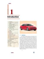
Bicycle gear mechanism switches the chain between different sized sprockets at the pedals and on
the back wheel. Going up hill, a small front and a large rear sprocket are selected to reduce the
push required for the rider. On the level, a large front and small rear. sprocket are used to prevent the
rider having to pedal too fast.
Going up hill
On the level
Idler
sprocket
Chain
Gear cable
pulls on
mechanism
Derailleur mechanism
Tensioner
Sprocket
set
Hub
Spur Gears
n
1039
elastic limit of the material. It is also called the basic stress. In order to account for the dynamic
effects which become more severe as the pitch line velocity increases, the value of σ
w
is reduced.
According to the Barth formula, the permissible working stress,
σ
w
= σ
o
× C
v
where σ
o
= Allowable static stress, and
C
v
= Velocity factor.
The values of the velocity factor (C
v
) are given as follows :
C
v
=
3
,
3 v
+
for ordinary cut gears operating at velocities upto 12.5 m / s.
=
4.5
,
4.5 v
+
for carefully cut gears operating at velocities upto 12.5 m/s.
=
6
,
6 v
+
for very accurately cut and ground metallic gears
operating at velocities upto 20 m / s.
=
0.75
,
0.75 v
+
for precision gears cut with high accuracy and
operating at velocities upto 20 m / s.
=
0.75
0.25,
1 v
+
+
for non-metallic gears.
In the above expressions, v is the pitch line velocity in metres per second.
The following table shows the values of allowable static stresses for the different gear
materials.
TT
TT
T
aa
aa
a
ble 28.4.ble 28.4.
ble 28.4.ble 28.4.
ble 28.4.
VV
VV
V
alues of alloalues of allo
alues of alloalues of allo
alues of allo
ww
ww
w
aa
aa
a
ble stable sta
ble stable sta
ble sta
tic strtic str
tic strtic str
tic str
essess
essess
ess
.
Material Allowable static stress (σ
o
) MPa or N/mm
2
Cast iron, ordinary 56
Cast iron, medium grade 70
Cast iron, highest grade 105
Cast steel, untreated 140
Cast steel, heat treated 196
Forged carbon steel-case hardened 126
Forged carbon steel-untreated 140 to 210
Forged carbon steel-heat treated 210 to 245
Alloy steel-case hardened 350
Alloy steel-heat treated 455 to 472
Phosphor bronze 84
Non-metallic materials
Rawhide, fabroil 42
Bakellite, Micarta, Celoron 56
Note : The allowable static stress (σ
o
) for steel gears is approximately one-third of the ultimate tensile stregth
(σ
u
) i.e. σ
o
= σ
u
/3.
1040
n
A Textbook of Machine Design
28.1928.19
28.1928.19
28.19
Dynamic Dynamic
Dynamic Dynamic
Dynamic
TT
TT
T
ooth Loadooth Load
ooth Loadooth Load
ooth Load
In the previous article, the velocity factor was used to make approximate allowance for the
effect of dynamic loading. The dynamic loads are due to the following reasons :
1. Inaccuracies of tooth spacing,
2. Irregularities in tooth profiles, and
3. Deflections of teeth under load.
A closer approximation to the actual conditions may be made by the use of equations based on
extensive series of tests, as follows :
W
D
= W
T
+ W
I
where W
D
= Total dynamic load,
W
T
= Steady load due to transmitted torque, and
W
I
= Increment load due to dynamic action.
The increment load (W
I
) depends upon the pitch line velocity, the face width, material of the
gears, the accuracy of cut and the tangential load. For average conditions, the dynamic load is
determined by using the following Buckingham equation, i.e.
W3.
Spur Gears
n
1041
where K = A factor depending upon the form of the teeth.
= 0.107, for
1
2
14
°
full depth involute system.
= 0.111, for 20° full depth involute system.
= 0.115 for 20° stub system.
E
P
= Young's modulus for the material of the pinion in N/mm
2
.
E
G
= Young's modulus for the material of gear in N/mm
2
.
e = Tooth error action in mm.
The maximum allowable tooth error in action (e) depends upon the pitch line velocity (v) and
the class of cut of the gears. The following tables show the values of tooth errors in action (e) for the
different values of pitch line velocities and modules.
TT
TT
T
aa
aa
a
ble 28.6.ble 28.6.
ble 28.6.ble 28.6.
ble 28.6.
VV
VV
V
alues of maximalues of maxim
alues of maximalues of maxim
alues of maxim
um alloum allo
um alloum allo
um allo
ww
ww
w
aa
aa
a
ble tooth errble tooth err
ble tooth errble tooth err
ble tooth err
or in action (or in action (
or in action (or in action (
or in action (
ee
ee
e
) v) v
) v) v
) v
erer
erer
er
ses pitch lineses pitch line
ses pitch lineses pitch line
ses pitch line
vv
vv
v
elocityelocity
elocityelocity
elocity
,,
,,
,
f f
f f
f
or wor w
or wor w
or w
ell cut commerell cut commer
ell cut commerell cut commer
ell cut commer
cial gearcial gear
cial gearcial gear
cial gear
ss
ss
s
.
Pitch line Tooth error in Pitch line Tooth error in Pitch line Tooth error in
velocity (v) m/s action (e) mm velocity (v) m/s action (e) mm velocity (v) m/s action (e) mm
1.25 0.0925 8.75 0.0425 16.25 0.0200
2.5 0.0800 10 0.0375 17.5 0.0175
3.75 0.0700 11.25 0.0325 20 0.0150
5 0.0600 12.5 0.0300 22.5 0.0150
6.25 0.0525 13.75 0.0250 25 and over 0.0125
7.5 0.0475 15 0.0225
TT
TT
T
aa
aa
a
ble 28.7.ble 28.7.
ble 28.7.ble 28.7.
ble 28.7.
VV
VV
V
alues of tooth erralues of tooth err
alues of tooth erralues of tooth err
alues of tooth err
or in action (or in action (
or in action (or in action (
or in action (
ee
ee
e
) v) v
) v) v
) v
erer
erer
er
ses module.ses module.
ses module.ses module.
ses module.
Tooth error in action (e) in mm
Module (m) in mm First class Carefully cut gears Precision gears
commercial gears
Upto 4 0.051 0.025 0.0125
5 0.055 0.028 0.015
6 0.065 0.032 0.017
7 0.071 0.035 0.0186
8 0.078 0.0386 0.0198
9 0.085 0.042 0.021
10 0.089 0.0445 0.023
12 0.097 0.0487 0.0243
14 0.104 0.052 0.028
16 0.110 0.055 0.030
18 0.114 0.058 0.032
20 0.117 0.059 0.033
1042
n
A Textbook of Machine Design
28.2028.20
28.2028.20
28.20
StaSta
StaSta
Sta
tic tic
tic tic
tic
TT
TT
T
ooth Loadooth Load
ooth Loadooth Load
ooth Load
The static tooth load (also called beam strength or endurance strength of the tooth) is obtained
by Lewis formula by substituting flexural endurance limit or elastic limit stress (σ
e
) in place of
permissible working stress (σ
w
).
∴ Static tooth load or beam strength of the tooth,
W
S
= σ
e
.b.p
c
.y = σ
e
.b.π m.y
The following table shows the values of flexural endurance limit (σ
e
) for different materials.
TT
TT
T
aa
aa
a
ble 28.8.ble 28.8.
ble 28.8.ble 28.8.
ble 28.8.
VV
VV
V
alues of falues of f
alues of falues of f
alues of f
lele
lele
le
xural endurance limit.xural endurance limit.
xural endurance limit.xural endurance limit.
xural endurance limit.
Material of pinion and Brinell hardness number Flexural endurance
gear (B.H.N.) limit (σ
e
) in MPa
Grey cast iron 160 84
Semi-steel 200 126
Phosphor bronze 100 168
Steel 150 252
200 350
240 420
280 490
300 525
320 560
350 595
360 630
400 and above 700
For safety, against tooth breakage, the static tooth load (W
S
) should be greater than the dynamic
load (W
D
). Buckingham suggests the following relationship between W
S
and W
D
.
For steady loads, W
S
≥ 1.25 W
D
For pulsating loads, W
S
≥ 1.35 W
D
For shock loads, W
S
≥ 1.5 W
D
Note : For steel, the flexural endurance limit (σ
e
) may be obtained by using the following relation :
σ
e
= 1.75 × B.H.N. (in MPa)
28.2128.21
28.2128.21
28.21
WW
WW
W
ear ear
ear ear
ear
TT
TT
T
ooth Loadooth Load
ooth Loadooth Load
ooth Load
The maximum load that gear teeth can carry, without premature wear, depends upon the radii of
curvature of the tooth profiles and on the elasticity and surface fatigue limits of the materials. The
maximum or the limiting load for satisfactory wear of gear teeth, is obtained by using the following
Buckingham equation, i.e.
W
w
= D
P
.b.Q.K
where W
w
= Maximum or limiting load for wear in newtons,
D
P
= Pitch circle diameter of the pinion in mm,
b = Face width of the pinion in mm,
Q = Ratio factor
=
G
GP
2
2
,
1
T
VR
VR T T
×
=
++
for external gears
=
G
GP
2
2
,
–1 –
T
VR
VR T T
×
=
for internal gears.
V. R. = Velocity ratio = T
G
/ T
P
,
K = Load-stress factor (also known as material combination factor) in
N/mm
2
.
Spur Gears
n
1043
The load stress factor depends upon the maximum fatigue limit of compressive stress, the pressure
angle and the modulus of elasticity of the materials of the gears. According to Buckingham, the load
stress factor is given by the following relation :
K =
2
PG
()sin
11
1.4
es
EE
σφ
+
where σ
es
= Surface endurance limit in MPa or N/mm
2
,
φ = Pressure angle,
E
P
= Young's modulus for the material of the pinion in N/mm
2
, and
E
G
= Young's modulus for the material of the gear in N/mm
2
.
The values of surface endurance limit (σ
es
) are given in the following table.
TT
TT
T
aa
aa
a
ble 28.9.ble 28.9.
ble 28.9.ble 28.9.
ble 28.9.
VV
VV
V
alues of surfalues of surf
alues of surfalues of surf
alues of surf
ace endurance limit.ace endurance limit.
ace endurance limit.ace endurance limit.
ace endurance limit.
Material of pinion Brinell hardness number Surface endurance limit
and gear (B.H.N.) (σ
es
) in N/mm
2
Grey cast iron 160 630
Semi-steel 200 630
Phosphor bronze 100 630
Steel 150 350
200 490
240 616
280 721
300 770
320 826
350 910
400 1050
Intermediate gear wheels
Blades
Gearwheel to turn
the blades
Driving gear wheel
Clutch lever
Roller
An old model of a lawn-mower
1044
n
A Textbook of Machine Design
Notes : 1. The surface endurance limit for steel may be obtained from the following equation :
σ
es
= (2.8 × B.H.N. – 70) N/mm
2
2. The maximum limiting wear load (W
w
) must be greater than the dynamic load (W
D
).
28.2228.22
28.2228.22
28.22
Causes of Gear Causes of Gear
Causes of Gear Causes of Gear
Causes of Gear
TT
TT
T
ooth Footh F
ooth Footh F
ooth F
ailurailur
ailurailur
ailur
ee
ee
e
The different modes of failure of gear teeth and their possible remedies to avoid the failure, are
as follows :
1. Bending failure. Every gear tooth acts as a cantilever. If the total repetitive dynamic load
acting on the gear tooth is greater than the beam strength of the gear tooth, then the gear tooth with fail
in bending, i.e. the gear tooth with break.
In order to avoid such failure, the module and face width of the gear is adjusted so that the beam
strength is greater than the dynamic load.
2. Pitting. It is the surface fatigue failure which occurs due to many repetition of Hertz contact
stresses. The failure occurs when the surface contact stresses are higher than the endurance limit of
the material. The failure starts with the formation of pits which continue to grow resulting in the
rupture of the tooth surface.
In order to avoid the pitting, the dynamic load between the gear tooth should be less than the
wear strength of the gear tooth.
3. Scoring. The excessive heat is generated when there is an excessive surface pressure, high
speed or supply of lubricant fails. It is a stick-slip phenomenon in which alternate shearing and welding
takes place rapidly at high spots.
This type of failure can be avoided by properly designing the parameters such as speed, pressure and
proper flow of the lubricant, so that the temperature at the rubbing faces is within the permissible limits.
4. Abrasive wear. The foreign particles in the lubricants such as dirt, dust or burr enter between
the tooth and damage the form of tooth. This type of failure can be avoided by providing filters for the
lubricating oil or by using high viscosity lubricant oil which enables the formation of thicker oil film
and hence permits easy passage of such particles without damaging the gear surface.
5. Corrosive wear. The corrosion of the tooth surfaces is mainly caused due to the presence of
corrosive elements such as additives present in the lubricating oils. In order to avoid this type of wear,
proper anti-corrosive additives should be used.
28.2328.23
28.2328.23
28.23
Design PrDesign Pr
Design PrDesign Pr
Design Pr
ocedurocedur
ocedurocedur
ocedur
e fe f
e fe f
e f
or Spur Gearor Spur Gear
or Spur Gearor Spur Gear
or Spur Gear
ss
ss
s
In order to design spur gears, the following procedure may be followed :
1. First of all, the design tangential tooth load is obtained from the power transmitted and the
pitch line velocity by using the following relation :
W
T
=
S
P
C
v
×
(i)
where W
T
= Permissible tangential tooth load in newtons,
P = Power transmitted in watts,
*v = Pitch line velocity in m / s
,
60
DN
π
=
D = Pitch circle diameter in metres,
* We know that circular pitch,
p
c
= π D / T = π m (∵ m = D / T)
∴ D = m.T
Thus, the pitch line velocity may also be obtained by using the following relation, i.e.
v =
60 60 60
ππ
==
c
pTNDN mTN
where m = Module in metres, and
T = Number of teeth.
Spur Gears
n
1045
N = Speed in r.p.m., and
C
S
= Service factor.
The following table shows the values of service factor for different types of loads :
TT
TT
T
aa
aa
a
ble 28.10.ble 28.10.
ble 28.10.ble 28.10.
ble 28.10.
VV
VV
V
alues of seralues of ser
alues of seralues of ser
alues of ser
vice fvice f
vice fvice f
vice f
actoractor
actoractor
actor
.
Type of service
Type of load
Intermittent or 3 hours 8-10 hours per day Continuous 24 hours
per day per day
Steady 0.8 1.00 1.25
Light shock 1.00 1.25 1.54
Medium shock 1.25 1.54 1.80
Heavy shock 1.54 1.80 2.00
Note : 1. The above values for service factor are for enclosed well lubricated gears. In case of non-enclosed and
grease lubricated gears, the values given in the above table should be divided by 0.65.
2. Apply the Lewis equation as follows :
W
T
= σ
w
.b.p
c
.y = σ
w
.b.π m.y
=(σ
o
.C
v
) b.π m.y (∵ σ
w
= σ
o
.C
v
)
Notes : (i) The Lewis equation is applied only to the weaker of the two wheels (i.e. pinion or gear).
(ii) When both the pinion and the gear are made of the same material, then pinion is the weaker.
(iii) When the pinion and the gear are made of different materials, then the product of (σ
w
× y) or (σ
o
× y)
is the *deciding factor. The Lewis equation is used to that wheel for which (σ
w
× y) or (σ
o
× y) is less.
* We see from the Lewis equation that for a pair of mating gears, the quantities like W
T
, b, m and C
v
are
constant. Therefore (σ
w
× y) or (σ
o
× y) is the only deciding factor.
A bicycle with changeable gears.