THE FRACTAL STRUCTURE OF DATA REFERENCE- P10 potx
Bạn đang xem bản rút gọn của tài liệu. Xem và tải ngay bản đầy đủ của tài liệu tại đây (171.49 KB, 5 trang )
Hierarchical Reuse Model 3 1
Figure 1.17. TSO storage pools: distribution of track interarrival times.
Figure 1.18. TSO storage pools: distribution of record interarrival times.
32 THE FRACTAL STRUCTURE OF DATA REFERENCE
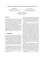
Figure 1.19. OS/390 system storage pools: distribution of track interarrival times.
Figure 1.20. OS/390 system storage pools: distribution of record interarrival times.
Hierarchical Reuse Model 33
single
-
reference residency time lengthens. Thus, as we should expect, these
plots suggest an important role for processor file buffers in the production
database storage pools.
In Chapters 3 and 5, we shall sometimes adopt a mathematical model in
which multiple workloads share the same cache or processor buffer area, and
each individual workload conforms to the hierarchical reuse model. This results
in a series of equations of the form (1.5), one for each workload. In graphical
terms, it corresponds to fitting each workload’s plot of interarrival statistics
with a straight line.
Collectively, Figures 1.2, 1.3, and 1.1 1 through 1.20 provide the justification
for adopting the mathematical model just described. The multiple workload
hierarchical reuse model, as just outlined in the previous paragraph, is both
sufficiently simple, and sufficiently realistic, to provide a practical framework
for examining how to get the most out of a cache shared by multiple, distinct
workloads.
34
THE FRACTAL STRUCTURE OF DATA REFERENCE
Notes
1 Assumes a track belonging to the 3380 family of storage devices.
2 Assumes a track belonging to the 3390 family of storage devices.
Chapter 2
HIERARCHICAL REUSE DAEMON
To conduct realistic performance benchmarks of storage subsystem perfor
-
mance, one attractive approach is to construct the required benchmark driver
out of building blocks that resemble, as closely as possible, actual applications
or users running in a realistic environment. This chapter develops a simple
“toy” version of an application whose pattern of reference conforms to the
hierarchical reuse model. Such a toy application can be implemented as an
independently executing “daemon” [19], and provides a natural building block
for
I/O performance testing. In addition, it helps bring to life, in the form of a
concrete example, the hierarchical reuse model itself.
It is reasonably simple to implement a toy application of the form that we
shall present, and to test its cache behavior directly against the characteristics of
the hierarchical reuse model. Nevertheless, this chapter also provides a crude,
asymptotic analysis to explain why we should expect the comparison to be a
favorable one.
To accomplish the needed analysis, we must first put the behavior of the
hierarchical reuse model into a form convenient for comparison against the
proposed toy application. With this background in place, we then propose, and
analyze, a method by which it is possible to match this behavior synthetically.
Finally, we illustrate the actual behavior of the proposed synthetic requests
through simulation.
1. DESIRED BEHAVIOR
Assuming that a pattern of requests obeys the hierarchical reuse model,
consider the expected arrival rate λ(t), to a specific track, after an amount of
time t has passed since some given
I/O request. The behavior of λ(t) provides
an alternative method of characterizing the hierarchical reuse model, which