Bearing Design in Machinery P2 ppt
Bạn đang xem bản rút gọn của tài liệu. Xem và tải ngay bản đầy đủ của tài liệu tại đây (256.34 KB, 20 trang )
load capacity of the bearing is limited by the available electrical power
supply from the amplifier.
e. Finally, electromagnetic bearings involve complex design problems to
ensure that the heavy spindle, with its high inertia, does not fall and
damage the magnetic bearing when power is shut off or momentarily
discontinued. Therefore, a noninterrupted power supply is required to
operate the magnetic bearing, even at no load or at shutdown condi-
tions of the system. In order to secure safe operation in case of
accidental power failure or support of the rotor during shutdown of
the machine, an auxiliary bearing is required. Rolling-element bearings
with large clearance are commonly used. During the use of such
auxiliary bearings, severe impact can result in premature rolling-
element failure.
1.6 ROLLING-ELEMENT BEARINGS
Rolling-element bearings, such as ball, cylindrical, or conical rolling bearings, are
the bearings most widely used in machinery. Rolling bearings are often referred
to as antifriction bearings. The most important advantage of rolling-element
bearings is the low friction and wear of rolling relative to that of sliding.
Rolling bearings are used in a wide range of applications. When selected
and applied properly, they can operate successfully over a long period of time.
Rolling friction is lower than sliding friction; therefore, rolling bearings have
lower friction energy losses as well as reduced wear in comparison to sliding
bearings. Nevertheless, the designer must keep in mind that the life of a rolling-
element bearing can be limited due to fatigue. Ball bearings involve a point
contact between the balls and the races, resulting in high stresses at the contact,
often named hertz stresses, after Hertz (1881), who analyzed for the first time the
stress distribution in a point contact.
When a rolling-element bearing is in operation, the rolling contacts are
subjected to alternating stresses at high frequency that result in metal fatigue. At
high speed, the centrifugal forces of the rolling elements, high temperature (due
to friction-energy losses) and alternating stresses all combine to reduce the
fatigue life of the bearing. For bearings operating at low and medium speeds,
relatively long fatigue life can be achieved in most cases. But at very high speeds,
the fatigue life of rolling element bearings can be too short, so other bearing types
should be selected. Bearing speed is an important consideration in the selection of
a proper type of bearing. High-quality rolling-element bearings, which involve
much higher cost, are available for critical high-speed applications, such as in
aircraft turbines.
Over the last few decades, a continuous improvement in materials and the
methods of manufacturing of rolling-element bearings have resulted in a
Copyright 2003 by Marcel Dekker, Inc. All Rights Reserved.
significant improvement in fatigue life, specifically for aircraft applications. But
the trend in modern machinery is to increase the speed of shafts more and more in
order to reduce the size of machinery. Therefore, the limitations of rolling-
element bearings at very high speeds are expected to be more significant in the
future.
The fatigue life of a rolling bearing is a function of the magnitude of the
oscillating stresses at the contact. If the stresses are low, the fatigue life can be
practically unlimited. The stresses in dry contact can be calculated by the theory
of elasticity. However, the surfaces are usually lubricated, and there is a very thin
lubrication film at very high pressure separating the rolling surfaces. This thin
film prevents direct contact and plays an important role in wear reduction. The
analysis of this film is based on the elastohydrodynamic (EHD) theory, which
considers the fluid dynamics of the film in a way similar to that of hydrodynamic
bearings.
Unlike conventional hydrodynamic theory, EHD theory considers the
elastic deformation in the contact area resulting from the high-pressure distribu-
tion in the fluid film. In addition, in EHD theory, the lubricant viscosity is
considered as a function of the pressure, because the pressures are much higher
than in regular hydrodynamic bearings. Recent research work has considered the
thermal effects in the elastohydrodynamic film. Although there has been much
progress in the understanding of rolling contact, in practice the life of the rolling-
element bearing is still estimated by means of empirical equations. One must
keep in mind the statistical nature of bearing life. Rolling bearings are selected to
have a very low probability of premature failure. The bearings are designed to
have a certain predetermined life span, such as 10 years. The desired life span
should be determined before the design of a machine is initiated.
Experience over many years indicates that failure due to fatigue in rolling
bearings is only one possible failure mode among many other, more frequent
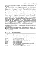
failure modes, due to various reasons. Common failure causes include bearing
overheating, misalignment errors, improper mounting, corrosion, trapped hard
particles, and not providing the bearing with proper lubrication (oil starvation or
not using the optimum type of lubricant). Most failures can be prevented by
proper maintenance, such as lubrication and proper mounting of the bearing.
Fatigue failure is evident in the form of spalling or flaking at the contact surfaces
of the races and rolling elements. It is interesting to note that although most
rolling bearings are selected by considering their fatigue life, only 5% to 10% of
the bearings actually fail by fatigue.
At high-speed operation, a frequent cause for rolling bearing failure is
overheating. The heat generated by friction losses is dissipated in the bearing,
resulting in uneven temperature distribution in the bearing. During operation, the
temperature of the rolling bearing outer ring is lower than that of the inner ring. In
turn, there is uneven thermal expansion of the inner and outer rings, resulting in
Copyright 2003 by Marcel Dekker, Inc. All Rights Reserved.
thermal stresses in the form of a tight fit and higher contact stresses between the
rolling elements and the races. The extra contact stresses further increase the level
of friction and the temperature. This sequence of events can lead to an unstable
closed-loop process, which can result in bearing failure by seizure. Common
rolling-element bearings are manufactured with an internal clearance to reduce
this risk of thermal seizure.
At high temperature the fatigue resistance of the metal is deteriorating.
Also, at high speed the centrifugal forces increase the contact stresses between the
rolling elements and the outer race. All these effects combine to reduce the
fatigue life at very high speeds. Higher risk of bearing failure exists whenever the
product of bearing load, F, and speed, n, is very high. The friction energy is
dissipated in the bearing as heat. The power loss due to friction is proportional to
the product Fn, similar to the product PV in a sleeve bearing. Therefore, the
temperature rise of the bearing relative to the ambient temperature is also
proportional to this product. In conclusion, load and speed are two important
parameters that should be considered for selection and design purposes. In
addition to friction-energy losses, bearing overheating can be caused by heat
sources outside the bearing, such as in the case of engines or steam turbines.
In aircraft engines, only rolling bearings are used. Hydrodynamic or
hydrostatic bearings are not used because of the high risk of a catastrophic
(sudden) failure in case of interruption in the oil supply. In contrast, rolling
bearings do not tend to catastrophic failure. Usually, in case of initiation of
damage, there is a warning noise and sufficient time to replace the rolling bearing
before it completely fails. For aircraft turbine engines there is a requirement for
ever increasing power output and speed. At the very high speed required for gas
turbines, the centrifugal forces of the rolling elements become a major problem.
These centrifugal forces increase the hertz stresses at the outer-race contacts and
shorten the bearing fatigue life.
The centrifugal force is proportional to the second power of the angular
speed. Similarly, the bearing size increases the centrifugal force because of its
larger rolling-element mass as well as its larger orbit radius. The DN value
(rolling bearing bore, in millimeters, times shaft speed, in revolutions per minute,
RPM) is used as a measure for limiting the undesired effect of the centrifugal
forces in rolling bearings. Currently, the centrifugal force of the rolling elements
is one important consideration for limiting aircraft turbine engines to 2 million
DN.
Hybrid bearings, which have rolling elements made of silicon nitride and
rings made of steel, have been developed and are already in use. One important
advantage of the hybrid bearing is that the density of silicon nitride is much lower
than that of steel, resulting in lower centrifugal force. In addition, hybrid bearings
have better fatigue resistance at high temperature and are already in use for many
industrial applications. Currently, intensive tests are being conducted in hybrid
Copyright 2003 by Marcel Dekker, Inc. All Rights Reserved.
bearings for possible future application in aircraft turbines. However, due to the
high risk in this application, hybrid bearings must pass much more rigorous tests
before actually being used in aircraft engines.
Thermal stresses in rolling bearings can also be caused by thermal
elongation of the shaft. In machinery such as motors and gearboxes, the shaft
is supported by two bearings at the opposite ends of the shaft. The friction energy
in the bearings increases the temperature of the shaft much more than that of the
housing of the machine. It is important to design the mounting of the bearings
with a free fit in the housing on one side of the shaft. This bearing arrangement is
referred to as a locating=floating arrangement; it will be explained in Chapter 13.
This arrangement allows for a free thermal expansion of the shaft in the axial
direction and elimination of the high thermal stresses that could otherwise
develop.
Rolling-element bearings generate certain levels of noise and vibration, in
particular during high-speed operation. The noise and vibrations are due to
irregular dimensions of the rolling elements and are also affected by the internal
clearance in the bearing.
1.7 SELECTION CRITERIA
In comparison to rolling-element bearings, limited fatigue life is not a major
problem for hydrodynamic bearings. As long as a full fluid film completely
separates the sliding surfaces, the life of hydrodynamic bearings is significantly
longer than that of rolling bearings, particularly at very high speeds.
However, hydrodynamic bearings have other disadvantages that make other
bearing types the first choice for many applications. Hydrodynamic bearings can
be susceptible to excessive friction and wear whenever the journal surface has
occasional contact with the bearing surface and the superior fluid film lubrication
is downgraded to boundary or mixed lubrication. This occurs at low operating
speeds or during starting and stopping, since hydrodynamic bearings require a
certain minimum speed to generate an adequate film thickness capable of
completely separating the sliding surfaces.
According to the theory that is discussed in the following chapters, a very
thin fluid film is generated inside a hydrodynamic bearing even at low journal
speed. But in practice, due to surface roughness or vibrations and disturbances, a
certain minimum speed is required to generate a fluid film of sufficient thickness
that occasional contacts and wear between the sliding surfaces are prevented.
Even at high journal speed, surface-to-surface contact may occur because of
unexpected vibrations or severe disturbances in the system.
An additional disadvantage of hydrodynamic bearings is a risk of failure if
the lubricant supply is interrupted, even for a short time. A combination of high
speed and direct contact is critical, because heat is generated in the bearing at a
Copyright 2003 by Marcel Dekker, Inc. All Rights Reserved.
very fast rate. In the case of unexpected oil starvation, the bearing can undergo a
catastrophic (sudden) failure. Such catastrophic failures are often in the form of
bearing seizure (welding of journal and bearing) or failure due to the melting of
the bearing lining material, which is often a white metal of low melting
temperature. Without a continuous supply of lubricant, the temperature rises
because of the high friction from direct contact.
Oil starvation can result from several causes, such as failure of the oil pump
or the motor. In addition, the lubricant can be lost due to a leak in the oil system.
The risk of a catastrophic failure in hydrodynamic journal bearings is preventing
their utilization in important applications where safety is involved, such as in
aircraft engines, where rolling-element bearings with limited fatigue life are
predominantly used.
For low-speed applications and moderate loads, plain sleeve bearings with
boundary lubrication can provide reliable long-term service and can be an
adequate alternative to rolling-element bearings. In most industrial applications,
these bearings are made of bronze and lubricated by grease or are self-lubricated
sintered bronze. For light-duty applications, plastic bearings are widely used. As
long as the product of the average pressure and speed, PV , is within the specified
design values, the two parameters do not generate excessive temperature.
If plain sleeve bearings are designed properly, they wear gradually and do
not pose the problem of unexpected failure, such as fatigue failure in rolling-
element bearings. When they wear out, it is possible to keep the machine running
for a longer period before the bearing must be replaced. This is an important
advantage in manufacturing machinery, because it prevents the financial losses
involved in a sudden shutdown. Replacement of a plain sleeve bearing can, at
least, be postponed to a more convenient time (in comparison to a rolling
bearing). In manufacturing, unexpected shutdown can result in expensive loss
of production. For sleeve bearings with grease lubrication or oil-impregnated
porous metal bearings, the manufacturers provide tables of maximum speed and
load as well as maximum PV value, which indicate the limits for each bearing
material. If these limits are not exceeded, the temperature will not be excessive,
resulting in a reliable operation of the bearing. A solved problem is included at
the end of this chapter.
Sleeve bearings have several additional advantages. They can be designed
so that it is easier to mount and replace them, in comparison to rolling bearings.
Sleeve bearings can be of split design so that they can be replaced without
removing the shaft. Also, sleeve bearings can be designed to carry much higher
loads, in comparison to rolling bearings, where the load is limited due to the high
‘‘hertz’’stresses. In addition, sleeve bearings are usually less sensitive than rolling
bearings to dust, slurry, or corrosion caused by water infiltration.
However, rolling bearings have many other advantages. One major advan-
tage is their relatively low-cost maintenance. Rolling bearings can operate with a
Copyright 2003 by Marcel Dekker, Inc. All Rights Reserved.
minimal quantity of lubrication. Grease-packed and sealed rolling bearings are
very convenient for use in many applications, since they do not require further
lubrication. This significantly reduces the maintenance cost.
In many cases, machine designers select a rolling bearing only because it is
easier to select from a manufacturer’s catalogue. However, the advantages and
disadvantages of each bearing type must be considered carefully for each
application. Bearing selection has long-term effects on the life of the machine
as well as on maintenance expenses and the economics of running the machine
over its full life cycle. In manufacturing plants, loss of production is a dominant
consideration. In certain industries, unplanned shutdown of a machine for even 1
hour may be more expensive than the entire maintenance cost or the cost of the
best bearing. For these reasons, in manufacturing, bearing failure must be
prevented without consideration of bearing cost. In aviation, bearing failure can
result in the loss of lives; therefore, careful bearing selection and design are
essential.
1.8 BEARINGS FOR PRECISION APPLICATIONS
High-precision bearings are required for precision applications, mostly in
machine tools and measuring machines, where the shaft (referred to as the
spindle in machine tools) is required to run with extremely low radial or axial run-
out. Therefore, precision bearings are often referred to as precision spindle
bearings. Rolling bearings are widely used in precision applications because in
most cases they provide adequate precision at reasonable cost.
High-precision rolling-element bearings are manufactured and supplied in
several classes of precision. The precision is classified by the maximum allowed
tolerance of spindle run-out. In machine tools, spindle run-out is undesirable
because it results in machining errors. Radial spindle run-out in machine tools
causes machining errors in the form of deviation from roundness, while axial run-
out causes manufacturing errors in the form of deviation from flat surfaces.
Rolling-element bearing manufacturers use several tolerance classifications, but
the most common are the following three tolerance classes of precision spindle
bearings (FAG 1986):
Maximum
Precision class run-out (mm)
1. High-precision rolling-element bearings 2.0
2. Special-precision bearings 1.0
3. Ultraprecision bearings 0.5
Copyright 2003 by Marcel Dekker, Inc. All Rights Reserved.
Detailed discussion of rolling-element bearing precision is included in
Chapter 13. Although rolling-element bearings are widely used in high-precision
machine tools, there is an increasing requirement for higher levels of precision.
Rolling-element bearings always involve a certain level of noise and vibrations,
and there is a limit to their precision. The following is a survey of other bearing
types, which can be alternatives for high precision applications
1.9 NONCONTACT BEARINGS FOR PRECISION
APPLICATIONS
Three types of noncontact bearings are of special interest for precision machin-
ing, because they can run without any contact between the sliding surfaces in the
bearing. These noncontact bearings are hydrostatic, hydrodynamic, and electro-
magnetic bearings. The bearings are noncontact in the sense that there is a thin
clearance of lubricant or air between the journal (spindle in machine tools) and
the sleeve. In addition to the obvious advantages of low friction and the absence
of wear, other characteristics of noncontact bearings are important for ultra-high-
precision applications. One important characteristic is the isolation of the spindle
from vibrations. Noncontact bearings isolate the spindle from sources of vibra-
tions in the machine or even outside the machine. Moreover, direct contact
friction can induce noise and vibrations, such as in stick-slip friction; therefore,
noncontact bearings offer the significant advantage of smooth operation for high-
precision applications. The following discussion makes the case that hydrostatic
bearings are the most suitable noncontact bearing for high-precision applications
such as ultra-high-precision machine tools.
The difference between hydrodynamic and hydrostatic bearings is that, for
the first, the pressure is generated inside the bearing clearance by the rotation
action of the journal. In contrast, in a hydrostatic bearing, the pressure is supplied
by an external pump. Hydrodynamic bearings have two major disadvantages that
rule them out for use in machine tools: (a) low stiffness at low loads, and (b) at
low speeds, not completely noncontact, since the fluid film thickness is less than
the size of surface asperities.
In order to illustrate the relative advantage of hydrostatic bearings, it is
interesting to compare the nominal orders of magnitude of machining errors in
the form of deviation from roundness. The machining errors result from spindle
run-out. Higher precision can be achieved by additional means to isolate the
spindle from external vibrations, such as from the driving motor. In comparison
to rolling-element bearings, experiments in hydrostatic-bearings indicated the
following machining errors in the form of deviation from roundness by machine
tools with a spindle supported by hydrostatic bearings (see Donaldson and
Patterson, 1983 and Rowe, 1967):
Copyright 2003 by Marcel Dekker, Inc. All Rights Reserved.
Precison class Machining
error (mm)
1. Regular hydrostatic bearing 0.20
2. When vibrations are isolated from the drive 0.05
Experiments indicate that it is important to isolate the spindle from
vibrations from the drive. Although a hydrostatic bearing is supported by a
fluid film, the film has relatively high stiffness and a certain amount of vibrations
can pass through, so additional means for isolation of vibrations is desirable. The
preceding figures illustrate that hydrostatic bearings can increase machining
precision, in comparison to precision rolling bearings, by one order of magnitude.
The limits of hydrostatic bearing technology probably have not been reached yet.
1.10 BEARING SUBJECTED TO FREQUENT
STARTS A ND ST OPS
In addition to wear, high start-up friction in hydrodynamic journal bearings
increases the temperature of the journal much more than that of the sleeve, and
there is a risk of bearing seizure. There is uneven thermal expansion of the journal
and bearing, and under certain circumstances the clearance can be completely
eliminated, resulting in bearing seizure. Bearing seizure poses a higher risk than
wear, since the failure is catastrophic. This is the motivation for much research
aimed at reducing start-up friction.
According to hydrodynamic theory, a very thin fluid film is generated even
at low journal speed. But in practice, due to surface roughness, vibrations, and
disturbances, a certain high minimum speed is required to generate an adequate
film thickness so that occasional contacts and wear between the sliding surfaces
are prevented. The most severe wear occurs during starting because the journal is
accelerated from zero velocity, where there is relatively high static friction. The
lubricant film thickness increases with speed and must be designed to separate the
journal and sleeve completely at the rated speed of the machine. During starting,
the speed increases, the fluid film builds up its thickness, and friction is reduced
gradually.
In applications involving frequent starts, rolling element bearings are
usually selected because they are less sensitive to wear during start-up and
stopping. But this is not always the best solution, because rolling bearings have a
relatively short fatigue-life when the operating speed is very high. In Chapter 18,
it is shown that it is possible to solve these problems by using a ‘‘composite
Copyright 2003 by Marcel Dekker, Inc. All Rights Reserved.
bearing,’’ which is a unique design of hydrodynamic and rolling bearings in
series (Harnoy and Rachoor, 1993).
Manufacturers continually attempt to increase the speed of machinery in
order to reduce its size. The most difficult problem is a combination of high
operating speed with frequent starting and stopping. At very high speed, the life
of the rolling-element bearing is short, because fatigue failure is partly deter-
mined by the number of cycles, and high speed results in reduced life (measured
in hours). In addition to this, at high speed the centrifugal forces of the rolling
elements (balls or rollers) increase the fatigue stresses. Furthermore, the
temperature of the bearing rises at high speeds; therefore, the fatigue resistance
of the material deteriorates. The centrifugal forces and temperature exacerbate the
problem and limit the operating speed at which the fatigue life is acceptable. Thus
the two objectives, longer bearing life and high operating speed, are in conflict
when rolling-element bearings are used. Hydrodynamic bearings operate well at
high speeds but are not suitable for frequent-starting applications.
Replacing the hydrodynamic bearing with an externally pressurized hydro-
static bearing can eliminate the wear and friction during starting and stopping.
But a hydrostatic bearing is uneconomical for many applications, since it requires
an oil pump system, an electric motor, and flow restrictors in addition to the
regular bearing system. An example of a unique design of a composite bearing—
hydrodynamic and rolling bearings in series—is described in chapter 18. This
example is a low-cost solution to the problem involved when high-speed
machinery are subjected to frequent starting and stopping.
In conclusion, the designer should keep in mind that the optimum operation
of the rolling bearing is at low and moderate speeds, while the best performance
of the hydrodynamic bearing is at relatively high speeds. Nevertheless, in
aviation, high-speed rolling-element bearings are used successfully. These are
expensive high-quality rolling bearings made of special steels and manufactured
by unique processes for minimizing impurity and internal microscopic cracks.
Materials and manufacturing processes for rolling bearings are discussed in
Chapter 13.
1.11 EXAMPLE PROBLEMS
Example Problem 1-1
PV Limits
Consider a shaft supported by two bearings, as shown in Fig. 1-6. The two
bearings are made of self-lubricated sintered bronze. The bearing on the left side
is under radial load, F
r
¼ 1200 lbf, and axial load, F
a
¼ 0:5F
r
. (The bearing on
the right supports only radial load). The journal diameter is D ¼ 1 inch, and the
Copyright 2003 by Marcel Dekker, Inc. All Rights Reserved.
bearing length L ¼ D. The thrust load is supported against a shaft shoulder of
diameter D
1
¼ 1:2D. The shaft speed is N ¼ 1000 RPM.
Sintered bronze has the following limits:
Surface velocity limit, V ,is6m=s, or 1180 ft=min.
Surface pressure limit, P, is 14 MPa, or 2000 psi.
PV limit is 110,000 psi-ft=min, or 3:85 Â10
6
Pa-m=s
a. For the left-side bearing, find the P, V , and PV values for the thrust
bearing (in imperial units) and determine if this thrust bearing can
operate with a sintered bronze bearing material.
b. For the left-side bearing, also find the P, V, and PV values for the
radial bearing (in imperial units) and determine if the radial bearing can
operate with sintered bronze bearing material.
Summary of data for left bearing:
F
r
¼ 1200 lbf
F
a
¼ 0:5F
r
¼ 600 lbf
D ¼ 1in: ¼ 0:083 ft ðjournal diameterÞ
D
1
¼ 1:2in: ¼ 0:1ft ðshoulder diameterÞ
N ¼ 1000 RPM
Solution
a. Thrust Bearing
Calculation of Average Pressure, P. The average pressure, P, in the axial
FIG. 1-6 Journal bearing under radial and thrust load.
Copyright 2003 by Marcel Dekker, Inc. All Rights Reserved.
direction is,
P ¼
F
a
A
where
A ¼
p
4
ðD
2
1
À D
2
Þ
This is the shoulder area that supports the thrust load. Substituting yields
P ¼
4F
a
pðD
2
1
À D
2
Þ
¼
4 Â 600
pð1:2
2
À 1
2
Þ
¼ 1736 psi
This is within the allowed limit of P
allowed
¼ 2000 psi.
b. Calculation of Average Surface Velocity of Thrust Bearing, V
th
. The
average velocity of a thrust bearing is at the average diameter, ðD
1
þ DÞ=2:
V
th
¼ oR
av
¼ o
D
av
2
where o ¼ 2pN rad=min. Substituting yields
V
th
¼ 2pNR
av
¼
2pNðD
1
þ DÞ
4
¼ 0:5pNðD
1
þ DÞ
Substitution in the foregoing equation yields
V
th
¼ 0:5p  1000 rev=min ð0:1 þ 0:083Þ ft ¼ 287:5ft=min
This is well within the allowed limit of V
allowed
¼ 1180 ft=min.
c. Calculation of Actual Average PV Value for the Thrust Bearing:
PV ¼ 1736 psi Â287:5ft=min ¼ 500 Â 10
3
psi-ft=min
Remark. The imperial units for PV are of pressure, in psi, multiplied by
velocity, in ft=min.
Conclusion. Although the limits of the velocity and pressure are met, the
PV value exceeds the allowed limit for self-lubricated sintered bronze bearing
material, where the PV limit is 110,000 psi-ft=min.
b. Radial Bearing
Calculation of Average Pressure
P ¼
F
r
A
Copyright 2003 by Marcel Dekker, Inc. All Rights Reserved.
where A ¼ LD is the projected area of the bearing. Substitution yields
P ¼
F
r
LD
¼
1200 lbf
1in: Â 1in:
¼ 1200 psi
Calculation of Journal Surface Velocity. The velocity is calculated as
previously; however, this time the velocity required is the velocity at the surface
of the 1-inch shaft, D=2.
V
r
¼ o
D
2
¼ 2pn
D
2
¼ p  1000 rev=min  0:083 ft ¼ 261 ft= min
Calculation of Average PV Value:
PV ¼ 1200 psi Â261 ft=min ¼ 313 Â10
3
psi-ft=min
In a similar way to the thrust bearing, the limits of the velocity and pressure are
met; however, the PV value exceeds the allowed limit for sintered bronze bearing
material, where the PV limit is 110,000 psi-ft=min.
Example Problem 1-2
Calculation of Bearing Forces
In a gearbox, a spur gear is mounted on a shaft at equal distances from two
supporting bearings. The shaft and gear turn together at a speed of 600 RPM. The
gearbox is designed to transmit a maximum power of 5 kW. The gear pressure
angle is f ¼ 20
. The diameter of the gear pitch circle is d
p
¼ 5 in.
Remark. The gear pressure angle f (PA) is the angle between the line of
force action (normal to the contact area) and the direction of the velocity at the
pitch point (see Fig. 1-7). Two standard pressure angles f for common involute
gears are f ¼ 20
and f ¼ 14:5
. Detailed explanation of the geometry of gears
is included in many machine design textbooks, such as Machine Design,by
Deutschman et al. (1975), or Machine Design, by Norton (1996).
a. Find the reaction force on each of the two bearings supporting the
shaft.
b. The ratio of the two bearings’ length and bore diameter is L=D ¼ 0:5.
The bearings are made of sintered bronze material (PV ¼ 110;000 psi-
ft=min). Find the diameter and length of each bearing that is required in
order not to exceed the PV limit.
Solution
a. Reaction Forces
Given:
Copyright 2003 by Marcel Dekker, Inc. All Rights Reserved.
Rotational speed N ¼ 600 RPM
Power
_
EE ¼ 5000 W
Diameter of pitch circle d
p
¼ 5 in.
Pressure angle f ¼ 20
PV
allowed
¼ 110;000 psi-ft=min
L=D ¼ 0:5 (the bore diameter of the bearing, D, is very close to that of the
journal, d)
Conversion Factors:
1psi ¼ 6895 N=m
2
1ft=min ¼ 5:08 Â10
À3
m=s
1 psi-ft=min ¼ 35 N=m
2
-m=s
The angular velocity, o, of the journal is:
o ¼
2pN
60
¼
2p600
60
¼ 52:83 rad=s
Converting the diameter of the pitch circle to SI units,
d
p
¼ 5in: Â 0:0254 m=in: ¼ 0:127 m
FIG. 1-7 Gear pressure angle.
Copyright 2003 by Marcel Dekker, Inc. All Rights Reserved.
The tangential force, F
t
, acting on the gear can now be derived from the power,
_
EE:
_
EE ¼ T o
where the torque is
T ¼
F
t
d
p
2
Substituting into the power equation:
_
EE ¼
F
t
d
p
o
2
and solving for F
t
and substituting yields
F
t
¼
2
_
EE
d
p
o
¼
2 Â 5000 Nm=s
0:127 m Â62:83 rad=s
¼ 1253:2N
In spur gears, the resultant force acting on the gear is F ¼ F
tr
(Fig. 1-7)
cos f ¼
F
t
F
so
F ¼
F
t
cos f
¼
1253:2
cos 20
¼ 1333:6N
The resultant force, F, acting on the gear is equal to the radial component of the
force acting on the bearing. Since the gear is equally spaced between the two
bearings supporting the shaft, each bearing will support half the load, F.
Therefore, the radial reaction, W , of each bearing is
W ¼
F
2
¼
1333:6
2
¼ 666:8N
b. Bearing Dimensions
The average bearing pressure, P,is
P ¼
F
A
Here, A ¼ LD, where D is the journal diameter and A is the projected area of the
contact surface of journal and bearing surface,
P ¼
F
LD
Copyright 2003 by Marcel Dekker, Inc. All Rights Reserved.
The velocity of shaft surface, V,is
V ¼
D
2
o
Therefore,
PV ¼
W
LD
D
2
o
Since L=D ¼ 0:5, L ¼ 0:5D, substituting and simplifying yields
PV ¼
W
0:5D
2
oD
2
¼
W
D
o
The PV limit for self-lubricated sintered bronze is given in English units,
converted to SI units, the limit is
110;000 psi-ft=min Â35 N=m
2
-m=s ¼ 3;850;000 Pa-m=s
Solving for the journal diameter, D, and substituting yields the diameter of the
bearing:
D ¼
W o
PV
¼
666:8NÂ62:83 rad=s
3:85 Â10
6
Pa Á m=s
¼ 0:011 m; or D ¼ 11 mm
The length of the bearing, L,is
L ¼ 0:5D ¼ 0:5 Â11 mm ¼ 5:5mm
The resulting diameter, based on a PV calculation, is very small. In actual design,
the journal is usually of larger diameter, based on strength-of-material considera-
tions, because the shaft must have sufficient diameter for transmitting the torque
from the drive.
Example Problem 1-3
Calculation of Reaction Forces
In a gearbox, one helical gear is mounted on a shaft at equal distances from two
supporting bearings. The helix angle of the gear is c ¼ 30
, and the pressure
angle (PA) is f ¼ 20
. The shaft speed is 3600 RPM. The gearbox is designed to
transmit maximum power of 20 kW. The diameter of the pitch circle of the gear is
equal to 5 in. The right-hand-side bearing is supporting the total thrust load. Find
the axial and radial loads on the right-hand-side bearing and the radial load on the
left-side bearing.
Copyright 2003 by Marcel Dekker, Inc. All Rights Reserved.
Solution
The angular velocity of the shaft, o, is:
o ¼
2pN
60
¼
2p3600
60
¼ 377 rad=s
Torque produced by the gear is T ¼ F
t
d
p
=2. Substituting this into the power
equation,
_
EE ¼ To, yields:
_
EE ¼
F
t
d
p
2
o
Solving for the tangential force, F
t
, results in
F
t
¼
2
_
EE
d
p
o
¼
2 Â 20;000 N-m=s
0:127 m Â377 rad=s
¼ 836 N
Once the tangential component of the force is solved, the resultant force, F, and
the thrust load (axial force), F
a
, can be calculated as follows:
F
a
¼ F
t
tan c
F
a
¼ 836 N Â tan 30
¼ 482 N
and the radial force component is:
F
r
¼ F
t
tan f
¼ 836 N Â tan 20
¼ 304 N
The force components, F
t
and F
r
, are both in the direction normal to the shaft
centerline. The resultant of these two gear force components, F
tr
, is cause for the
radial force component in the bearings. The resultant, F
tr
, is calculated by the
equation (Fig. 1-7)
F
tr
¼
ffiffiffiffiffiffiffiffiffiffiffiffiffiffiffiffiffi
F
2
t
þ F
2
r
q
¼
ffiffiffiffiffiffiffiffiffiffiffiffiffiffiffiffiffiffiffiffiffiffiffiffiffi
836
2
þ 304
2
p
¼ 890 N
The resultant force, F
tr
, on the gear is supported by the two bearings. It is a radial
bearing load because it is acting in the direction normal to the shaft centerline.
Since the helical gear is mounted on the shaft at equal distances from both
bearings, each bearing will support half of the radial load,
W
r
¼
F
tr
2
¼
890 N
2
¼ 445 N
However, the thrust load will act only on the right-hand bearing:
F
a
¼ 482 N
Copyright 2003 by Marcel Dekker, Inc. All Rights Reserved.
Example Problem 1-4
Calculation of Reaction Forces
In a gearbox, two helical gears are mounted on a shaft as shown in Fig. 1-1. The
helix angle of the two gears is c ¼ 30
, and the pressure angle (PA) is f ¼ 20
.
The shaft speed is 3600 RPM. The gearbox is designed to transmit a maximum
power of 10 kW. The pitch circle diameter of the small gear is equal to 5 in. and
that of the large gear is of 15 in.
a. Find the axial reaction force on each of the two gears and the resultant
axial force on each of the two bearings supporting the shaft.
b. Find the three load components on each gear, F
t
, F
r
, and F
a
.
Solution
Given:
Helix angle c ¼ 30
Pressure angle f ¼ 20
Rotational speed N ¼ 3600 RPM
Power 10 kW
Diameter of pitch circle (small) d
P1
¼ 5in:
Diameter of pitch circle (large) d
P2
¼ 15 in:
Small Gear
a. Axial Reaction Forces.
The first step is to solve for the tangential force acting on the small gear, F
t
.
It can be derived from the power, E, and shaft speed:
_
EE ¼ T o
where the torque is T ¼ F
t
d
p
=2. The angular speed o in rad=sis
o ¼
2pN
60
¼
2p  3600
60
¼ 377 rad=s
Substituting into the power equation yields
_
EE ¼
F
t
d
p
o
2
The solution for F
t
acting on the small gear is given by
F
t
¼
2
_
EE
d
p
o
The pitch diameter is 5 in., or d
p
¼ 0:127 m. After substitution, the tangential
force is
F
t
¼
2 Â 10;000 W
ð0:127 mÞÂð377 rad=sÞ
¼ 418 N
Copyright 2003 by Marcel Dekker, Inc. All Rights Reserved.
The radial force on the gear (F
r
in Fig 1-1) is:
F
r
¼ F
t
tan f
F
r
¼ 418 N Â tan 20
F
r
¼ 152 N
b. Calculation of the Thrust Load, F
a
:
The axial force on the gear is calculated by the equation,
F
a
¼ F
t
tan c
¼ 418 N Â tan 30
¼ 241 N
F
t
¼ 418 N
F
r
¼ 152 N
F
a
¼ 241 N
Large gear
The same procedure is used for the large gear, and the results are:
F
t
¼ 140 N
F
r
¼ 51 N
F
a
¼ 81 N
Thrust Force on a Bearing
One bearing supports the total thrust force on the shaft. The resultant thrust load
on one bearing is the difference of the two axial loads on the two gears, because
the thrust reaction forces in the two gears are in opposite directions (see Fig. 1-1):
F
a
ðbearingÞ¼241 À 81 ¼ 180 N
Problems
1-1 Figure 1-4 shows a drawing of a hydrostatic journal bearing system
that can support only a radial load. Extend this design and sketch a
hydrostatic bearing system that can support combined radial and
thrust loads.
1-2 In a gearbox, a spur gear is mounted on a shaft at equal distances
from two supporting bearings. The shaft and mounted gear turn
together at a speed of 3600 RPM. The gearbox is designed to transmit
a maximum power of 3 kW. The gear contact angle is f ¼ 20
. The
pitch diameter of the gear is d
p
¼ 30 in. Find the radial force on each
of the two bearings supporting the shaft.
The ratio of the two bearings’ length and diameter is
L=D ¼ 0:5. The bearings are made of acetal resin material with the
Copyright 2003 by Marcel Dekker, Inc. All Rights Reserved.
following limits:
Surface velocity limit, V ,is5m=s.
Average surface-pressure limit, P, is 7 MPa.
PV limit is 3000 psi-ft=min.
Find the diameter of the shaft in order not to exceed the stated limits.
1-3 A bearing is made of Nylon sleeve. Nylon has the following limits as
a bearing material:
Surface velocity limit, V ,is5m=s.
Average surface-pressure limit, P, is 6.9 MPa.
PV limit is 3000 psi-ft=min.
The shaft is supported by two bearings, as shown in Fig. 1-6. The
bearing on the left side is under a radial load F
r
¼ 400 N and an axial
load F
a
¼ 200 N . (The bearing on the left supports the axial force.)
The journal diameter is d, and the bearing length L ¼ d. The thrust
load is supported against a shaft shoulder of diameter D ¼ 1:2d. The
shaft speed is N ¼ 800 RPM. For the left-side bearing, find the
minimum journal diameter d that would result in P, V, and PV
below the allowed limits, in the radial and thrust bearings.
1-4 In a gearbox, one helical gear is mounted on a shaft at equal distances
from two supporting bearings. The helix angle of the gear is c ¼ 30
,
and the pressure angle (PA) is f ¼ 20
. The shaft speed is
1800 RPM. The gearbox is designed to transmit a maximum power
of 12 kW. The diameter of the pitch circle of the gear is 5 in. The
right-hand-side bearing is supporting the total thrust load. Find the
axial and radial load on the right-hand-side bearing and the radial
load on the left-side bearing.
1-5 In a gearbox, two helical gears are mounted on a shaft as shown in
Fig. 1-1. The helix angle of the two gears is f ¼ 30
, and the pressure
angle (PA) is f ¼ 20
. The shaft speed is 3800 RPM. The gearbox is
designed to transmit a maximum power of 15 kW. The pitch circle
diameters of the two gears are 5 in. and 15 in. respectively.
a. Find the axial reaction force on each of the two gears and
the resultant axial force on each of the two bearings
supporting the shaft.
b. Find the three load components on each gear, F
t
, F
r
,and
F
a
.
Copyright 2003 by Marcel Dekker, Inc. All Rights Reserved.
2
Lubricant Viscosity
2.1 INTRODUCTION
For hydrodynamic lubrication, the viscosity, m, is the most important character-
istic of a fluid lubricant because it has a major role in the formation of a fluid film.
However, for boundary lubrication the lubricity characteristic is important. The
viscosity is a measure of the fluid’s resistance to flow. For example, a low-
viscosity fluid flows faster through a capillary tube than a fluid of higher
viscosity. High-viscosity fluids are thicker, in the sense that they have higher
internal friction to the movement of fluid particles relative to one another.
Viscosity is sensitive to small changes in temperature. The viscosity of
mineral and synthetic oils significantly decreases (the oils become thinner) when
their temperature is raised. The higher viscosity is restored after the oils cool
down to their original temperature. The viscosity of synthetic oils is relatively less
sensitive to temperature variations (in comparison to mineral oils). But the
viscosity of synthetic oils also decreases with increasing temperature.
During bearing operation, the temperature of the lubricant increases due to
the friction, in turn, the oil viscosity decreases. For hydrodynamic bearings, the
most important property of the lubricant is its viscosity at the operating bearing
temperature. One of the problems in bearing design is the difficulty of precisely
predicting the final temperature distribution and lubricant viscosity in the fluid
film of the bearing. For a highly loaded bearing combined with slow speed, oils of
Copyright 2003 by Marcel Dekker, Inc. All Rights Reserved.