Tài liệu Sensors in Manufacturing (P2) pptx
Bạn đang xem bản rút gọn của tài liệu. Xem và tải ngay bản đầy đủ của tài liệu tại đây (882.21 KB, 20 trang )
sult of their relatively low cost, these are expected to be the ‘sensors of choice’ in
the future.
The six types of signal outputs listed above reflect the 10 basic forms of energy
that sensors convert from one form to another. These are listed in Table 1.2-1 [3,
5, 6]. In practice, these 10 forms of energy are condensed into the six signal types
listed as we can consider atomic and molecular energy as part of chemical energy,
gravitational and mechanical as one, mechanical, and we can ignore nuclear and
mass energy. The six signal types (hence basic sensor types for our discussion) re-
present ‘measurands’ extracted from manufacturing processes that give us insight
into the operation of the process. These measurands represent measurable ele-
ments of the process and, further, derive from the basic information conversion
technique of the sensor. That is, depending on the sensor, we will probably have
differing measurands from the process. However, the range of measurands avail-
able is obviously closely linked to the type of (operating principle) of the sensor
employed. Table 1.2-2, adapted from [7], defines the relevant measurands from a
range of sensing technologies. The ‘mapping’ of these measurand/sensing pairs
on to a manufacturing process is the basis of developing a sensing strategy for a
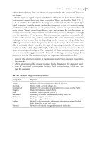
process or system. The measurands give us important information on the:
· process (the electrical stability of the process, in electrical discharge machining,
for example),
· effects of outputs of the process (surface finish, dimension, for example), and
· state of associated consumables (cutting fluid contamination, lubricants, tool-
ing, for example).
1.2 Principles of Sensors in Manufacturing 11
Tab. 1.2-1
Forms of energy converted by sensors
Energy form Definition
Atomic Related to the force between nuclei and electrons
Electrical Electric fields, current, voltage, etc.
Gravitational Related to the gravitation attraction between a mass and the Earth
Magnetic Magnetic fields and related effects
Mass Following relativity theory (E=mc
2
)
Mechanical Pertaining to motion, displacement/velocity, force, etc.
Molecular Binding energy in molecules
Nuclear Binding energy in electrons
Radiant Related to electromagnetic radiowaves, microwaves, infrared, visible
light, ultraviolet, x-rays and c-rays
Thermal Related to the kinetic energy of atoms and molecules
1 Fundamentals12
Tab. 1.2-2
Process measurands associated with sensor signal types (after [7])
Signal output type Associated process measurands
Mechanical (includes acoustic) Position (linear, angular)
Velocity
Acceleration
Force
Stress, pressure
Strain
Mass, density
Moment, torque
Flow velocity, rate of transport
Shape, roughness, orientation
Stiffness, compliance
Viscosity
Crystallinity, structural integrity
Wave amplitude, phase, polarization, spectrum
Wave velocity
Electrical Charge, current
Potential, potential difference
Electric field (amplitude, phase, polarization, spectrum)
Conductivity
Permittivity
Magnetic Magnetic field (amplitude, phase, polarization, spectrum)
Magnetic flux
Permeability
Chemical (includes biological) Components (identities, concentrations, states)
Biomass (identities, concentrations, states)
Radiation Type
Energy
Intensity
Emissivity
Reflectivity
Transmissivity
Wave amplitude, phase, polarization, spectrum
Wave velocity
Thermal Temperature
Flux
Specific heat
Thermal conductivity
Finally, there are a number of technical specifications of sensors that must be ad-
dressed in assessing the ability of a particular sensor/output combination to mea-
sure robustly the state of the process. These specifications relate to the operating
characteristics of the sensors and are usually the basis for selecting a particular
sensor from a specific vendor, eg [7]:
· ambient operating conditions;
· full-scale output;
· hysteresis;
· linearity;
· measuring range;
· offset;
· operating life;
· output format;
· overload characteristics;
· repeatability;
· resolution;
· selectivity;
· sensitivity;
· response speed (time constant);
· stability/drift.
It is impossible to detail the associated specifications for the six sensing technolo-
gies under discussion here. A number of references have done this for specific
sensors for manufacturing applications, eg, Shiraishi [8–10] and Allocca and
Stuart [2]. Others are referenced elsewhere in this volume or reviewed in [11].
1.2.3
Basic Sensor Types
1.2.3.1
Mechanical Sensors
Mechanical sensors are perhaps the largest and most diverse type of sensors be-
cause, as seen in Table 1.2-2, they have the largest set of potential measurands.
Force, motion, vibration, torque, flow, pressure, etc., are basic elements of most
manufacturing processes and of great interest to measure as an indication of pro-
cess state or for control. Force is a push or pull on a body that results in motion/
displacement or deformation. Force transducers, a basic mechanical sensor, are
designed to measure the applied force relative to another part of the machine
structure, tooling, or workpiece as a result of the behavior of the process. A num-
ber of mechanisms convert this applied force (or torque) into a signal, including
piezoelectric crystals, strain gages, and potentiometers (as a linear variable differ-
ential transformer (LVDT)). Displacement, as in the motion of an axis of a ma-
chine, is measurable by mechanical sensors (again the LVDT or potentiometer) as
well as by a host of other sensor types to be discussed. Accelerometer outputs, dif-
ferentiated twice, can yield a measure of displacement of a mechanism. Shiraishi
[9] relies on a number of mechanical sensing elements to measure the dimen-
1.2 Principles of Sensors in Manufacturing 13
sions of a workpiece. Flow is commonly measured by ‘flow meters’, mechanical
devices with rotameters (mechanical drag on a float in the fluid stream) as well as
venturi meters (relying on differential pressure measurement, using another me-
chanical sensor) to determine the flow of fluids. An excellent review of other me-
chanical sensing (and transducing) devices is given in [2].
Mechanical sensors have seen the most advances owing to the developments in
semiconductor fabrication technology. Piezo-resistive and capacitance-based de-
vices, basic building blocks of silicon micro-sensors, are now routinely applied to
pressure, acceleration, and flow measurements in machinery. Figure 1.2-2a shows
the schematics of a capacitive sensor with applications in pressure sensing (the
silicon diaphragm deflects under the pressure of the gas/fluid and modifies the
capacitance between the diaphragm and another electrode in the device). Using a
beam with a mass on the end as one plate of the capacitor and a second electrode
(Figure 1.2-2 b), an accelerometer is constructed and the oscillation of the mass/
beam alters the capacitance in a measurable pattern allowing the determination of
the acceleration. Figure 1.2-3 shows a TRW NovaSensor
®
, a miniature, piezoresis-
tive chip batch fabricated and diced from silicon wafers. These sensor chips can
be provided as basic original equipment manufacturer (OEM) sensor elements or
can be integrated into a next-level packaging scheme. These devices are con-
1 Fundamentals14
Fig. 1.2-2
Schematic of a capacitance sensor for (a) pressure and (b) acceleration
structed using conventional semiconductor fabrication technologies based on the
semiconducting materials and miniaturization of very large scale integrated
(VLSI) patterning techniques (see, for example, Sze [1] as an excellent reference
on semiconductor sensors). The development of microelectromechanical sensing
systems (so-called MEMS) techniques has opened a wide field of design and appli-
cation of special micro-sensors (mechanical and others) for sophisticated sensing
tasks. Figure 1.2-4 shows a MEMS gyroscope fabricated at UC Berkeley BSAC for
use in positioning control of shop-floor robotic devices. In fact, most of the six
1.2 Principles of Sensors in Manufacturing 15
Fig. 1.2-3
Piezoresistive micro-
machined pressure die. Courtesy
of Lucas NovaSensor, 2000
Fig. 1.2-4
Detail of MEMS gyroscope chip
(0.5 cm ´0.5 cm) with 2 lm feature size. Cour-
tesy Wyatt Davis, BSAC, UC Berkeley, 2000
basic sensor types can be accommodated by this technology. Accelerometers are
built on these chips as already discussed. Whatever affects the frequency of oscil-
lation of the silicon beam of the sensor can be considered a measurand. Coating
the accelerometer beam with a material that absorbs certain chemical elements,
hence changing the mass of the beam and its resonant frequency, changes this
into a chemical sensor. Similar modifications yield other sensor types.
One particularly interesting type of micro-sensor for pressure applications, not
based on the capacitance principles discussed above, is silicon-on-sapphire (SOS).
This is specially applicable to pressure-sensing technology. Manufacturing an SOS
transducer begins with a sapphire wafer on which silicon is epitaxially grown on
the smooth, hard, glass-like surface of the sapphire. Since the crystal structure of
the silicon film is similar to sapphire’s, the SOS structure appears to be one crys-
tal with a strong molecular bond between the two materials. The silicon is then
etched into a Wheatstone bridge pattern using conventional photolithography
techniques. Owing to its excellent chemical resistance and mechanical properties,
the sapphire wafer itself may be used as the sensing diaphragm. An appropriate
diaphragm profile is generated in the wafer to create the desired flexure of the
diaphragm and to convey the proper levels of strain to the silicon Wheatstone
bridge. The diaphragm may be epoxied or brazed to a sensor package. A more re-
liable method of utilizing the SOS technology involves placing an SOS wafer on a
machined titanium diaphragm. In this configuration titanium becomes the pri-
mary load-bearing element and a thin (thickness under 0.01 in) SOS wafer is
used as the sensing element. The SOS wafer is bonded to titanium using a pro-
cess similar to brazing, performed under high mechanical pressure and tempera-
ture conditions in vacuum to ensure a solid, stable bond between the SOS wafer
and the titanium diaphragm. The superb corrosion resistance of titanium allows
compatibility with a wide range of chemicals that may attack epoxies, elastomers,
and even certain stainless steels. The titanium diaphragm is machined using con-
ventional machining techniques and the SOS wafer is produced using conven-
tional semiconductor processing techniques. SOS-based pressure sensors with op-
erating pressures ranging from 104 kPa to over 414 MPa are available.
Acoustic sensors have benefited from the developments in micro-sensor tech-
nology. Semiconductor acoustic sensors employ elastic waves at frequencies in the
range from megahertz to low gigahertz to measure physical and chemical (in-
cluding biological) quantities. There are a number of basic types of these sensors
based upon the mode of flexure of an elastic membrane or bulk material in the
sensor is employed. Early sensors of this type used vibrating piezoelectric crystal
plates referred to as a quartz crystal microbalance (QCM). It is also called a thick-
ness shear-mode sensor (TSM) after the mode of particle motion employed. Other
modes of acoustic wave motion employed in these devices (with appropriate de-
sign) include surface acoustic wave (SAW) for waves travelling on the surface of a
solid, and elastic flexural plate wave (FPW) for waves travelling in a thin mem-
brane. The cantilever devices described earlier are also in this class.
1 Fundamentals16
1.2.3.2
Thermal Sensors
Thermal sensors generally function by transforming thermal energy (or the ef-
fects of thermal energy) into a corresponding electrical quantity that can be
further processed or transmitted. Other techniques for sensing thermal energy (in
the infrared range) are discussed under radiant sensors below. Typically, a non-
thermal signal is first transduced into a heat flow, the heat flow is converted into
a change in temperature/temperature difference, and, finally, this temperature dif-
ference is converted into an electrical signal using a temperature sensor. Micro-
sensors employ thin membranes (floating membrane cantilever beam, for exam-
ple). There is a large thermal resistance between the tip of the beam and the base
of the beam where it is attached to the device rim. Heat dissipated at the tip of
the beam will induce a temperature difference in the beam. Thermocouples
(based on the thermoelectric Seebeck effect whereby a temperature difference at
the junction of two metals creates an electrical voltage) or transistors are em-
ployed to sense the temperature difference in the device outputting an electrical
signal proportional to the difference. Recent advances in thermal sensor applica-
tion to the ‘near surface zone’ of materials for assessing structural damage (re-
ferred to as photo-thermal inspection) were reported by Goch et al. [12]. This re-
view also covers other measurement techniques such as micromagnetic.
Thermal sensors are also employed in flow measurement following the well-
known principle of cooling of hot objects by the flow of a fluid (boundary layer
flow measurement anemometers). They can also be applied in thermal tracing
and heat capacity measurements in fluids. All three application areas are suitable
for silicon micro-sensor integration.
Thermal sensors have also found applicability traditionally in ‘true-rms conver-
ters’. Root mean square (rms) converters are used to convert the effective value of
an alternating current (AC) voltage or current to its equivalent direct current (DC)
value. This is accomplished simply by converting the electrical signal into heat
with the assistance of a resistor and measuring the temperature generated.
1.2.3.3
Electrical Sensors
Electrical sensors are intended to determine charge, current, potential, potential
difference, electric field (amplitude, phase, polarization, spectrum), conductivity
and permittivity and, as such, have some overlap with magnetic sensors. Power
measurement, an important measure of the behavior of many manufacturing pro-
cesses, is also included here. An example of the application of thermal sensors for
true rms power measurement was included with the discussion on thermal sen-
sors. The use of current sensors (perhaps employing principles of magnetic sens-
ing technology) is commonplace in machine tool monitoring [11]. Electrical resis-
tance measurement has also been widely employed in tool wear monitoring appli-
cations [8]. Most of the discussion on magnetic sensors below is applicable here
in consideration of the mechanisms of operation of electrical sensors.
1.2 Principles of Sensors in Manufacturing 17
1.2.3.4
Magnetic Sensors
A magnetic sensor converts a magnetic field into an electrical signal. Magnetic
sensors are applied directly as magnetometers (measuring magnetic fields) and
data reading (as in heads for magnetic data storage devices). They are applied in-
directly as a means for detecting nonmagnetic signals (eg, in contactless linear/
angular motion or velocity measurement) or as proximity sensors. Most magnetic
sensors utilize the Lorenz force producing a current component perpendicular to
the magnetic induction vector and original current direction (or a variation in the
current proportional to a variation in these elements). There are also Hall effect
sensors. The Hall effect is a voltage induced in a semiconductor material as it
passes through a magnetic field. Magnetic sensors are useful in nondestructive in-
spection applications where they can be employed to detect cracks or other flaws
in magnetic materials due to the perturbation of the magnetic flux lines by the
anomaly. Semiconductor-based magnetic sensors include thin-film magnetic sen-
sors (relying on the magnetoresistance of NiFe thin films), semiconductor mag-
netic sensors (Hall effect), optoelectronic magnetic sensors which use light as an
intermediate signal carrier (based on Faraday rotation of the polarization plane of
linearly polarized light due to the Lorenz force on bound electrons in insulators
[1]) and superconductor magnetic sensors (a special class).
1.2.3.5
Radiant Sensors
Radiation sensors convert the incident radiant signal energy (measurand) into
electrical output signals. The radiant signals are either electromagnetic, neutrons,
fast neutrons, fast electrons, or heavy-charge particles [1]. The range of electro-
magnetic frequencies is immense, spanning from cosmic rays on the high end
with frequencies in the 10
23
Hz range to radio waves in the low tens of thousands
of Hz. In manufacturing applications we are most familiar with infrared radiation
(10
11
–10
14
Hz) as a basis for temperature measurement or flaw/problem detec-
tion. Silicon-on-insulator photodiodes and phototransistors based on transistor ac-
tion are typical micro-sensor radiant devices [1] for use in these ranges.
1.2.3.6
Chemical Sensors
These sensors are becoming particularly more important in manufacturing pro-
cess monitoring and control. It is important to measure the identities of gases
and liquids, concentrations, and states, chemical sensors for worker safety (to in-
sure no exposure to hazardous materials or gases), process control (to monitor,
for example, the quality of fluids or gases used in production; this is especially
critical in the semiconductor industry which relies on complex process ‘recipes’
for successful production), and process state (presence or absence of a material,
eg, gas or fluid). Chemical sensors have been successfully produced as micro-sen-
sors using semiconductor technologies primarily for the detection of gaseous spe-
cies. Most of these devices rely on the interaction of chemical species at semicon-
ductor surfaces (adsorption on a layer of material, for example) and then the
1 Fundamentals18