The Complete IS-IS Routing Protocol- P13 ppsx
Bạn đang xem bản rút gọn của tài liệu. Xem và tải ngay bản đầy đủ của tài liệu tại đây (166.68 KB, 10 trang )
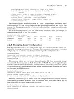
The System-ID field of the LSP-ID is displayed as a name. However, the origin
router’s System-ID is displayed with the show isis hostname command (the same
in IOS and JUNOS), which displays the hostname cache on the local router.
IOS command
IOS marks the local node with an asterisk (*):
Frankfurt#show isis hostname
Level System ID Dynamic Hostname
1921.6800.1013 London
* 1921.6800.1014 Frankfurt
1921.6800.1018 Washington
[…]
JUNOS command
JUNOS displays in addition if the entry has been learned via other routers, or if it has
been locally configured. The local node is always marked “Static”.
hannes@London> show isis hostname
IS-IS hostname database:
System ID Hostname Type
1921.6800.1013 London Static
1921.6800.1014 Frankfurt Dynamic
1921.6800.1018 Washington Dynamic
[…]
4.8 Summary
This chapter explored the foundations of IS-IS. The independence of area addressing and
routing hierarchy was contrasted to the OSPF model where Area 0 implicitly makes up a
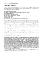
Names, System-, LAN- and LSP-IDs 107
1921.6820.4003.02-00
System-ID
Pseudonod
e-
ID
Fragment-
ID
F
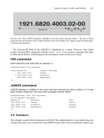
IGURE 4.24. The LSP-ID uniquely identifies an IS-IS router announcement – the first 6 bytes
represent the System-ID of the sender therefore the CLI renders the output using the Hostname-
to-System-ID database
routing hierarchy. The concept of an arbitrarily assigned level to the underlying physical
topology was explained. This flexibility allows IS-IS to make very resilient POP top-
ology without spending extra costs for physical intra-POP links just to heal the topology.
The IP addressing model and the OSI addressing model were discussed in a comparative
way; interestingly, the IS-IS model corresponds almost exactly to the unnumbered IP
routing model. IS-IS inherits its addressing structure from the OSI suite of protocols.
Address assignment is a relatively easy task. The fixed part of the NET can be calculated
based on the IP loopback address of the router and/or the POP/topology codes that are
unique to each service provider. The Area-ID is the only variable part in the system, and
based on network size, most IS-IS networks use 3 or 5 byte Area-IDs. Most Area-IDs
start with 49 because the 49/8 prefix has been allocated for private use – it is the RFC
1918 of the OSI suite. Finally, this chapter presented the IS-IS built-in name resolution
service and several commands to display those ID formats which benefit from the address
resolution service as well.
108 4. IS-IS Basics
Virtually all routing (and signalling) protocols include a method of automatic neighbour
discovery that enables a router to determine if there are any other adjacent routers running
the same routing protocol. Once you enable IS-IS on an interface, the routing protocol
will automatically find out if there are other routers out there speaking the same protocol
and version and immediately start to interact with these remote routers. Additionally the
routing protocol needs to verify if the link is two-way capable (that is, equally able to pass
protocol traffic in both directions) before it can announce a Reachability Information TLV
in a link-state PDU (LSP) and flood it throughout the topology. This verification of link
capabilities and bi-directional checks is done using a process known as handshaking. This
chapter examines how IS-IS routers perform neighbour discovery and handshaking on
LAN and WAN circuits. Additionally, different properties of handshaking methods, such as
the simple 2-way handshake and the inherent problems of using this 2-way handshaking
method are discussed.
You will also learn the details of adjacency finite state machine changes and network
stability improvement techniques like adjacency hold downs. Finally, requirements of
highly resilient neighbour “liveness” checking will be presented and popular solutions
will be explored including technologies like bi-directional fault detection. Everything
will include configuration snippets, show command and debug output, plus tcpdump out-
put for a better understanding of the IS-IS protocol.
5.1 Hello Message Encoding
Each routing protocol uses Hello messages for neighbour discovery and to perform
handshaking. In IS-IS, just like in any other routing protocol, this function is performed
through the use of what IS-IS calls Intermediate System to Intermediate System Hello
(IIH) messages. IS-IS uses dedicated IIH messages for the two types of topologies a
router can be configured to be a member of: there is one Hello type for the Level 1 adja-
cencies and one Hello type for the Level 2 adjacencies. There are more details about the
IS-IS hierarchical Level 1/Level 2 routing paradigm in Chapter 4 “IS-IS Basics”.
IS-IS supports two different circuit types: point-to-point (p2p) and broadcast LAN cir-
cuits. There is a dedicated type of Hello Message for point-to-point circuits and another
one for broadcast circuits. So in theory there should be two Hello messages for each cir-
cuit type (point-to-point or broadcast) and two Hello message types for each Level, L1
or L2. This should total four distinct Hello message types.
109
5
Neighbour Discovery and Handshaking
In ISO 10589, however, there was some concern that running two Hellos (one per
level) on point-to-point links would consume too much bandwidth on narrow-band links.
So IS-IS is optimized for point-to-point circuits and only uses one PDU type for both
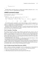
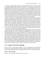
levels. Figure 5.1 shows the structure of the IS-IS common header, which starts every IS-IS
message. The 8-bit PDU type field indicates the type of message that is carried inside the
IS-IS message. On the right of the figure there is a list of the nine distinct PDU types for
IS-IS. Three out of the nine PDU types are reserved for Hello messages. The point-
to-point circuit types share one PDU type (17) for both levels, so there are not really
four different Hello messages but only three.
What do the Hello messages look like on the wire? Each IS-IS message type is
prepended with an 8-byte common header that tells the receiver about the IS-IS protocol
version being used, the header length, the maximum number of concurrent areas sup-
ported, as well as other IS-IS global parameters, such as the length of the System-ID
field. Figure 5.1 shows the structure of the common header that is prepended to all IS-IS
related messages. In the figure, you can see that some of the fields are already filled in
with number values. We have chosen not only to show the frame structure, but also to
show how the frames are populated with number values. These numbers represent con-
stants and fill in the common header with typical values. It is interesting to note that some
header fields, such as the number of supported areas and the length of the System-ID
field, are set to zero. Zero has a special meaning in IS-IS. Using the zero value is equiv-
alent to telling routers to use the default value for a field, which is not typically zero.
110 5. Neighbour Discovery and Handshaking
Intra-domain routing protocol discriminator
Header Length Indicator
Version/Protocol ID Extension
0x83
Bytes
1
1
1
1
1
1
1
1
1
ID Length
PDU Type
R
0
R
0
R
0
PDU Version
Reserved
Maximum Area Addresses
6 (0)
1
3 (0)
0
PDU specific fields
17–33
TLV section
0–1467
15
16
17
18
20
24
25
26
27
Level 1 LAN Hello
Level 2 LAN Hello
p2p Hello
Level 1 Link State PDU
Level 2 Link State PDU
Level 1 CSNP
Level 2 CSNP
Level 1 PSNP
Level 2 PSNP
PDU
Type
Name
15
Level LAN circuit p2p circuit
1
2
16
17
FIGURE 5.1. Three out of the nine IS-IS PDU types are allocated for Hello messages on p2p and
broadcast circuits
Oddly, because the default value is not explicitly set out in detail in IS-IS, each imple-
mentation has to intuitively know the default values. The default value for System-ID-
Length is 6 bytes and the default value for Maximum Area Addresses is 3, but these are
really de facto defaults and not set out as hard limitations.
You should now have a basic understanding of IS-IS Hello messages. The following
sections discuss LAN Hello messages and point-to-point messages in greater detail.
5.1.1 LAN Hello Messages
Figure 5.2 shows the structure of an IS-IS Hello message as it is used on LAN (IS-IS
broadcast) circuits. First there is the IS-IS common header. The header length of LAN
Hello messages is always set to 27 bytes – this represents the aggregate length of the
common header (8 bytes) and the LAN Hello header (19 bytes). The PDU type is either
15 or 16 depending on whether or not this is a Hello message targeted for Level 1 routers
or Level 2 routers respectively.
Hello Message Encoding 111
Intra-domain routing protocol discriminator
Header Length Indicator
Version/protocol ID Extension
0x83
Bytes
1
1
1
1
1
1
1
1
1
ID Length
PDU Type
R
0
R
0
R
0
PDU Version
Reserved
Maximum Area Addresses
6 (0)
1
3 (0)
0
Reserved
TLV section
0–1467
15, 16
27
circuit
type
1, 2, 3
Source ID
Holding Time
PDU Length
PriorityR
Designated IS LAN-ID
1
ID Length (6)
2
2
1
ID Length (6) ϩ 1
FIGURE 5.2. Structure of the L1, L2 LAN Hello PDU
The IS-IS LAN Hello message header starts with a field indicating which levels have
been configured on this circuit (the LAN). For the two lower order bits (the six other high
order bits are reserved and should be set to zero) there are three valid values:
•
0x1 Level 1 only
•
0x2 Level 2 only
•
0x3 Level 1 and Level 2
If the Circuit Type field is set to zero (both bits are zero, or “cleared” as code devel-
opers say) this represents an illegal value and the router will silently discard the Hello
message, assuming that there is something broken.
The Source-ID field contains the System-ID (the default length is 6 bytes) of the sender.
Holding Time represents the time after which the neighbour wants to be declared
dead. This sounds strange, but unlike humans, routers can specify their maximum ses-
sion lifetime. Typically, default holding time values are between 27 and 30 seconds
depending on the routing code implementation (IOS ϭ 30 seconds and JUNOS ϭ 27
seconds). Setting the holding time (for example) to 30 seconds is interpreted by the
receivers of the Hello message as follows: “If the neighbour router with the reported
System-ID does not send a Hello message for a period of 30 seconds, we’ll declare the
neighbour router dead and take appropriate action.” This action usually involves telling
the other neighbours that the adjacency relationship between these two routers has been
terminated. Each Hello message received resets the countdown number for this drop-
dead timer.
Figure 5.3 illustrates the sequence of events that refresh the hold timer. At t[0s], the
router receives a Hello message that sets the hold timer to 30 seconds. So the receiving
112 5. Neighbour Discovery and Handshaking
Neighbour
down
threshold
40
30
20
10
0
Hold Timer
(s)
10 20 30 40
50 60
New hello received
new hold time 30s,
reset hold timer
t (s)
New hello received
new hold time 30s,
reset hold timer
New hello received
new hold time
increased to 40s,
reset hold timer
FIGURE 5.3. Each Hello message resets the hold timer
router initializes a countdown timer, starting at 30 seconds. Next, the neighbouring
router will refresh the adjacency. To calculate the frequency for those refreshes there is a
constant called the Hello multiplier which is by default set to the value 3. The neigh-
bouring routers refreshes the Hello each (hold-timer divided by the Hello multiplier
time) period. Using the default values of 30/3, the adjacency should get a refresh every
10 seconds. If a router wants to lower the Hello frequency, no problem, as long as the
neighbouring router makes sure that the adjacency gets properly refreshed within the
hold-time period. The Hello message is resent every 10 seconds (or t[10s,20s], as repre-
sented in Figure 5.3) resulting in a saw-tooth shaped figure over time. A router can also
decide to change its hold-timer anytime – for example, at t[30s] a Hello message with the
hold time set to 40 seconds is received. This resets the countdown timer, as might be
expected, to 40 seconds. This is a unique capability among IP routing protocols: each
IS-IS router can set its hold-timer independently from every other router on the network.
This feature is quite different from OSPF networks where the Hello and the dead timer
have to match throughout entire sub-net, otherwise the routers will not form neighbour
adjacencies. On OSPF LANs, changing timers on the fly is disruptive and lacks the flexi-
bility that IS-IS gives you, unless you somehow manage to change all the Hello and
dead timers at the same point in time using a configuration script/robot. IS-IS is much
more operationally friendly in that respect, because IS-IS does not rely on any other
routers to match its timers like OSPF does. In OSPF, all the timers have to be aligned
with the designated router (DR).
In IS-IS such a change does not require any coordination/scripting effort. If you want
to change your own timers, you simply do it in a step-by-step fashion with no service dis-
ruption at all.
The PDU Length field contains the length of the entire packet including the common
header and the LAN Hello header.
The Priority and DIS LAN-ID fields are related to the election procedure of the
Designated Intermediate System (DIS). Chapter 7, “Pseudonodes and Designated
Routers”, contains a detailed description of why a DIS is needed and how the DIS
is elected on a LAN. The IS-IS DIS has much the same duties and functions as the
OSPF DR.
Multiple adjacencies on a circuit are displayed differently in the command line inter-
faces of Cisco and Juniper Networks. Cisco IOS displays multi-level LAN adjacencies in
one line, while JUNOS displays multi-level LAN adjacencies in two lines.
IOS command output
In IOS a Level 1 and Level 2 adjacency on a LAN circuit is displayed as L1L2 in the show
isis Adjacency output.
London#show clns neighbors
System Id Interface SNPA State Holdtime Type Protocol
Amsterdam GigE8/0 00a0.a512.3318 Up 21 L1L2 IS-IS
Pennsauken GigE4/0 00a0.a512.28d7 Up 18 L2 IS-IS
Frankfurt FastE5/0 0090.6900.fe27 Up 24 L2 IS-IS
Hello Message Encoding 113
114 5. Neighbour Discovery and Handshaking
Intra-domain routing protocol discriminator
Header Length Indicator
Version/Protocol ID Extension
0x83
Bytes
1
1
1
1
1
1
1
1
1
ID Length
PDU Type
R
0
R
0
R
0
PDU Version
Reserved
Maximum Area Addresses
6 (0)
1
3 (0)
0
Reserved
TLV section
4–1467
17
20
circuit
type
1, 2, 3
Source ID
Holding Time
PDU Length
Local circuit ID
1
ID Length (6) ϩ 1
2
2
1
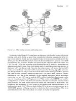
FIGURE 5.4. Structure of the point-to-point Hello PDU
JUNOS command output
In JUNOS a Level 1 and Level 2 adjacency on a point-to-point circuit is displayed as two
separate adjacencies in the show isis Adjacency output.
hannes@Munich> show isis Adjacency
Interface System L State Hold (secs) SNPA
ge-0/1/0.0 Vienna 2 Up 17 0:90:69:2b:e:7
ge-0/1/0.0 Vienna 1 Up 22 0:90:69:2b:e:7
ge-0/2/0.0 Munich-2 1 Up 21 0:90:69:2b:e:7
On point-to-point circuits there is a dedicated Hello type for adjacency management:
the point-to-point IIH PDU (17), which will be highlighted in the next section.
5.1.2 Point-to-point Hello Messages
Figure 5.4 shows the basic structure of a Hello message used on point-to-point cir-
cuits. The point-to-point Hello message is a little shorter than its LAN counterpart, but
essentially it contains the same set of information that the LAN Hello message does.
For instance, the point-to-point Hello contains:
•
Circuit Type
•
Source ID
•
Holding Time
•
PDU Length
All of these fields have the same meaning and function as in the LAN Hello. Note that
the Designated Router and Priority fields are missing. That’s because on point-to-point
circuits there is no election of a designated router, and so the point-to-point Hello mes-
sage does not need to carry the Priority and DIS LAN-ID fields.
Additionally, there is the Local Circuit-ID field that carries the link’s circuit number
The IS-IS specification leaves it quite open as to what value should be inserted for the
Local Circuit-ID. For example, in the IOS implementation, the Interface Index of the
sender’s interface is taken as the Local Circuit-ID. The JUNOS implementation always
sets this value to 0x1. The JUNOS implementers of this “constant” Local Circuit-ID
argue that the Circuit-ID is not needed anywhere for processing, such as in SPF calcula-
tions, timer countdowns, or anything else. The Local Circuit-ID is there for purely link-
local informational purposes. And if something has just informational purposes, then no
harm can be done by not setting it to anything other than a constant.
How can IS-IS build both Level 1 and Level 2 adjacencies on a point-to-point link with just
one message type? Figure 5.2 showed that LAN Hellos have two PDU types, one for each
level, whereas point-to-point Hellos share one PDU type for both levels. The difference in pro-
cessing the point-to-point Hello compared to the LAN Hello is that receipt of a point-to-point
Hello resets the hold timers for all levels, as indicated in the Circuit Type field. For example,
if the Circuit Type field indicates that this is just a Level 1 adjacency, then just the hold timer
of Level 1 is reset. The same logic goes for Level 2 and Level 1/Level 2 capable circuits –
whatever level is indicated in the Circuit Type, those corresponding hold timers get reset.
In contrast to point-to-point Hellos, receipt of a LAN Hello just resets the hold timer
according to the PDU type. A received Hello containing PDU Type 15 just resets the
Level 1 hold timer, while a PDU Type 16 resets the Level 2 hold timer only.
Command line interfaces of routers have different ways of displaying a joint Level
1/Level 2 adjacency. For example, JUNOS displays an L1L2 adjacency on a point-to-
point circuit as Level 3. Of course there is (yet) no Level 3, but the reason for this is sim-
ple: if you take the bit patterns of a Level 2 circuit (10b) plus the bit pattern of a Level 1
circuit (01b) the sum equals to (11b), which is the binary value for 3.
JUNOS command output
In JUNOS a Level 1 and Level 2 adjacency on a point-to-point circuit is displayed as
Level 3 in the show isis Adjacency output.
hannes@Frankfurt> show isis Adjacency
Interface System L State Hold (secs) SNPA
so-0/0/0.0 Munich 3 Up 28
so-0/1/0.0 London 2 Up 27
so-0/2/0.0 Milan 2 Up 25
so-1/0/0.0 paris 2 Up 24
Hello Message Encoding 115
IOS command output
In IOS a Level 1 and Level 2 adjacency on a point-to-point circuit is displayed as L1L2 in
the show clns neighbors output.
London#show clns neighbors
System Id Interface SNPA State Holdtime Type Protocol
Amsterdam PO4/0 *PPP* Up 19 L1L2 IS-IS
Pennsauken PO4/1 *PPP* Up 18 L2 IS-IS
Frankfurt PO4/1 *PPP* Up 24 L2 IS-IS
To summarize, Hello messages are the method used for discovering neighbours. IS-IS
routers send Hellos according to their configured link types, and wait for responses that
are a match. Receipt of a matching Hello message means another router on the link is at
least configured to run IS-IS. This is a good start, but not the whole story of establishing
and maintaining a full IS-IS router adjacency.
The next step is to check if the underlying circuit to the neighbour router is two-
way capable. Two-way capable means a pair of routers can transmit and receive their
peer’s Hello messages. A router needs to be sure that “I can see you and you can see
me”, before advertising an adjacency in its LSP. In order to verify two-way circuit
capability the router needs to perform a handshaking function. There are several differ-
ent handshake algorithms available and, unfortunately, some cannot even guarantee
that the underlying link is two-way capable, due to a mistake in the ISO 10589
specification.
Even if the router is fooled by a broken handshake mechanism, nothing breaks on
the network if (for example) the circuit is just one-way capable and the router announces
the one-way reachability (I can see you, but you cannot see me) in its router LSP. During the
SPF calculation there is a verification called the two-way check that makes sure no
transit path is calculated through a one-way circuit. The two-way check will be described
in more detail in Chapter 10 “SPF and Route Calculation”.
Before IS-IS starts to verify two-way connectivity over a link it actually probes
the link first to find out if it supports large packets for data exchange at a later
stage.
5.2 MTU Check
In IS-IS the largest packet (which is typically the LSP) may become 1492 bytes (MAC
layer excluded). IS-IS tests the link by artificially bloating its Hello size up to 1492 bytes.
There is a dedicated Message Element in the Hello PDU called a Padding TLV that is
used for this purpose. Figure 5.5 shows the structure of the Padding TLV #8. The
content of the Padding TLV is filled up with random data. The information that it
does contain does not matter – what matters is that it makes the PDU artificially big
up to maxLSPsize (ϭ1492 bytes). The tcpdump output below shows such a padded
Hello.
116 5. Neighbour Discovery and Handshaking