Sổ tay tiêu chuẩn thiết kế máy P2 pptx
Bạn đang xem bản rút gọn của tài liệu. Xem và tải ngay bản đầy đủ của tài liệu tại đây (1.53 MB, 29 trang )
threshold value
of the
third variable
can be
estimated
to
provide
a
specified reliabil-
ity.
The
actual value present
in the
design
or
part
can
then
be
compared
to the
threshold value
to see if the
part meets
the
desired reliability criteria
and is
then ade-
quate
for the
specifications provided.
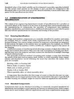
1.4
COMMUNICATIONOFENGINEERING
INFORMATION
The
output
of an
engineering department consists
of
specifications
for a
product
or
a
process.
Much
of the
output
is in the
form
of
drawings that convey instructions
for
the
manufacturing
of
components,
the
assembly
of
components into machines,
machine installations,
and
maintenance. Additional information
is
provided
by
parts
lists
and
written specifications
for
assembly
and
testing
of the
product.
1.4.1
Drawing Identification
Drawings
and
machine components
are
normally identified
by
number
and
name,
for
example, Part
no.
123456, Link.
Each
organization
has its own
system
of
num-
bering drawings.
One
system assigns numbers
in
sequence
as
drawings
are
prepared.
In
this system,
the
digits
in the
number have
no
significance;
for
example,
no.
123456
would
be
followed
by
numbers
123457,123458,
etc., without regard
to the
nature
of
the
drawing.
A
different
system
of
numbering detail drawings consists
of
digits that define
the
shape
and
nominal dimensions. This eases
the
task
of
locating
an
existing
part
draw-
ing
that
may
serve
the
purpose
and
thus reduces
the
likelihood
of
multiple drawings
of
nearly identical parts.
The
generally preferred method
of
naming parts assigns
a
name that describes
the
nature
of the
part, such
as
piston,
shaft,
fender,
or
wheel assembly. Some organi-
zations
add
descriptive words
following
the
noun that describes
the
nature
of its
part;
for
example:
Bearing, roller,
or
bearing, ball
Piston, brake,
or
piston, engine
Shaft,
axle,
or
shaft,
governor
Fender,
LH, or
fender,
RH
Wheel assembly, idler,
or
wheel assembly, drive
A
long name that describes
the
first
usage
of a
part
or
that ties
the
part
to a
par-
ticular
model
can be
inappropriate
if
other uses
are
found
for
that
part.
A
specific ball
or
roller bearing,
for
example, might
be
used
for
different
applications
and
models.
1.4.2
Standard
Components
Components that
can be
obtained according
to
commonly accepted standards
for
dimensions
and
strength
or
load capacity
are
known
as
standard
parts.
Such compo-
nents
can be
used
in
many
different
applications,
and
many organizations assign
part
numbers
from
a
separate
series
of
numbers
to the
components.
This
tends
to
elimi-
nate multiple part numbers
for the
same component
and
reduces
the
parts inven-
tory.
Standard components include such things
as
antifriction bearings, bolts, nuts,
machine screws, cotter pins, rivets,
and
Woodruff
keys.
1.4.3
Mechanical Drawings
Pictorial methods, such
as
perspective, isometric,
and
oblique projections,
can be
useful
for
visualizing shapes
of
objects. These methods, however,
are
very rarely used
for
working drawings
in
mechanical engineering. Orthographic projection,
in
which
a
view
is
formed
on a
plane
by
projecting perpendicularly
from
the
object
to the
plane,
is
used almost exclusively.
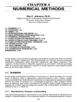
In
the
United States, mechanical drawings
are
made
in
what
is
known
as the
third-angle
projection.
An
example
is
provided
in
Fig. 1.4,
in
which
the
triangular
shape
can be
considered
to be the
front
view
or
front
elevation.
The top
view,
or
plan, appears above
the
front
view
and the
side view;
the
side elevation,
or end
view,
appears alongside
the
front
view.
In
this example,
the
view
of the
right-hand side
is
shown;
the
left-hand side would
be
shown
to the
left
of the
front
view
if it
were
needed.
FIGURE
1.4
Arrangement
of
views
of an
object
in
third-angle orthographic projection.
The
first-angle
projection
is
used
in
many other countries.
In
that arrangement,
the top
view
appears below
the
front
view,
and the
view
of the
left
side appears
to
the
right
of the
front
view. Some organizations
follow
the
practice
of
redoing draw-
ings
that
are to be
sent
to
different
countries
in
order
to
eliminate
the
confusion that
results
from
an
unfamiliar drawing arrangement.
Drawings,
with
the
exception
of
schematics,
are
made
to a
convenient scale.
The
choice
of
scale depends
on the
size
and
complexity
of the
object
and
fitting
it on a
standard size
of
drawing paper.
The
recommended inch sizes
of
drawings
are 8.5 x
11,11
x
17,17
x
22,22
x 34, and 34 x 44.
Then,
sizes
are
multiples
of the
size
of the
commercial letterhead
in
general use,
and
folded prints will
fit in
letter-sized
envelopes
and
files.
Drawings
should
be
made
to one of the
standard scales
in
common usage. These
are
full,
one-half, one-quarter,
and
one-eighth size.
If a
still smaller scale must
be
used,
the
mechanical engineer's
or
architect's rule
is
appropriate.
These
rules pro-
vide
additional scales ranging
from
1 in
equals
1 ft to
3
Az
in
equals
1 ft. The
civil engi-
neer's scale with decimal divisions
of 20, 30, 40, 50, and 60
parts
to the
inch
is not
appropriate
for
mechanical drawings.
Very
small parts
or
enlarged details
of
drawings
are
sometimes drawn larger than
full
size. Scales such
as 2, 4, 5, 10, or 20
times normal size
may be
appropriate,
depending
on the
particular situation.
Several
different
types
of
drawings
are
made,
but in
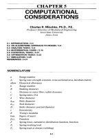
numbers produced,
the
detail drawing (Fig. 1.5) exceeds
all
other types.
A
detail
drawing provides
all
the
instructions
for
producing
a
component with
a
unique
set of
specifications.
The
drawing
specifies
the
material,
finished
dimensions, shape, surface
finish,
and
spe-
cial
processing (such
as
heat treatment
or
plating) required. Usually, each compo-
nent that
has a
unique
set of
specifications
is
given
a
separate
drawing.
There
are
numbering
systems, however,
in
which similar components
are
specified
on the
same drawing
and a
table specifies
the
dimensions that change
from
item
to
item.
Sometimes
the
material specification consists
of
another part
to
which operations
are
added.
For
example, another hole
or a
plating operation might
be
added
to an
existing
part. Detail drawings
are
discussed
in
considerable detail
in the
next por-
tion
of
this section.
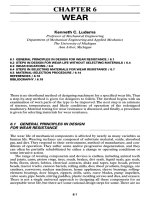
An
assembly
drawing
specifies
the
components that
are to be
joined
in a
perma-
nent assembly
and the
procedures required
to
make
the
assembly.
An
example
is
given
in
Fig. 1.6.
A
weldment,
for
example, will
specify
the
components that
are to be
welded,
the
weld locations,
and the
size
of
weld beads.
The
drawing
may
also
specify
operations that
are to be
performed
after
assembly, such
as
machining some areas.
Another type
of
assembly drawing consists
of an
interference
fit
followed
by
sub-
sequent machining.
A
bushing,
for
example,
may be
pressed into
the
machine
bore
of
the
upper
end of an
engine connecting rod,
and the
bushing
bore
may
then
be
machined
to a
specified dimension.
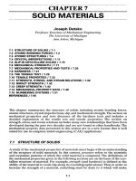
A
group drawing (Fig. 1.7)
may
resemble
a
layout
in
that
it
shows
a
number
of
components,
in
their proper relationship
to one
another, that
are
assembled
to
form
a
unit. This unit
may
then
be
assembled with other units
to
make
a
complete
machine.
The
drawing will normally include
a
parts list that identifies part numbers,
part names,
and the
required number
of
pieces.
A
group drawing might
be a
section
through
a
unit that must
be
assembled with other equipment
to
make
a
complete
machine.
A
machine outline drawing
is
provided
to
other engineering departments
or to
customers
who
purchase that machine
for
installation.
An
example
is
given
in
Fig.
1.8.
An
outline
may
show
the
general shape,
the
location
and
size
of
holes
for
mount-
ing
bolts,
the
shaft
diameter, keyseat dimensions,
locatiorkof
the
shaft
with respect
to
the
mounting holes,
and
some
major
dimensions./
\
Schematic
drawings,
such
as for
electrical
controls,
hydraulic systems,
and
piping
systems,
show
the
major
components
in
symbolic
form.
An
example
is
given
in
Fig.
1.9. They also show
the
manner
in
which
the
components
are
connected together
to
route
the
flow
of
electricity
or
fluids.
Schematic diagrams
are
sometimes provided
for
shop use,
but
more frequently they
are
used
in
instruction books
or
maintenance
manuals
where
the
functioning
of the
system
is
described.
FIGURE
1.5 An
example
of a
detail
drawing.
1.4.4
Detail Drawings
A
complete description
of the
shape
of a
part
is
provided
by the
views, sections,
and
specifications
on a
detail drawing.
A
simple part, such
as a
right-circular cylinder,
may
require only
one
view.
A
complex part, such
as an
engine cylinder block,
may
require several views
and
many sections
for an
adequate description
of the
geome-
try.
The
link
in
Fig.
1.5 is a
basically simple shape with added complexity
due to
machining.
The cut
surfaces
of
sections
are
indicated
by
section lining (crosshatch-
ing).
Standard symbols (Fig.
1.10)
1
are
available that indicate
the
type
of
material
sectioned.
The use of
proper section lining helps
the
user
to
understand
the
drawing
with
reduced clutter.
1
See
Sec.
1.6 for a
discussion
of
standards
and
standards organizations.
FIGURE
1.6 An
example
of an
assembly drawing.
Dimensions.
There
are two
reasons
for
providing dimensions:
(1) to
specify
size
and
(2) to
specify
location. Dimensioning
for
sizes,
in
many cases,
is
based
on the
common geometric
solids—cone,
cylinder, prism, pyramid,
and
sphere.
The
number
of
dimensions required
to
specify
these shapes varies
from
1 for the
sphere
to 3 for
the
prism
and
frustum
of a
cone. Location dimensions
are
used
to
specify
the
posi-
tions
of
geometric shapes with respect
to
axes, surfaces, other shapes,
or
other refer-
FIGURE
1.7 An
example
of a
group drawing.
FIGURE
1.8 An
example
of an
installation drawing.
ences.
A
sphere,
for
example,
is
located
by its
center.
A
cylinder
is
located
by its
axis
and
bases.
For
many years, dimensions were stated
in
terms
of
inches
and
common fractions
as
small
as
Ya*
in.
The
common fractions
are
cumbersome when adding
or
subtracting
dimensions,
and
decimal fractions
are now
used extensively.
The
decimal fractions
are
usually rounded
to two
digits following
the
decimal point unless
a
close
toler-
FIGURE
1.9 A
hydraulic schematic diagram.
ance
is to be
stated. Thus
% in,
which
is
precisely equal
to
0.375
in, is
normally speci-
fied
by
dimension
as
0.38
in.
The
advent
of the
International System
of
Units (SI)
has led to
detail drawings
on
which
dimensions
are
specified
in
metric units, usually millimeters (mm). Thus
Vi
mm
(very
nearly equal
to
0.020
in) is the
smallest dimension ordinarily specified without
stating
a
tolerance. Because machine
tools
and
measuring devices
are
still graduated
FIGURE 1.10 Symbols
for
section
lining. (ANSI standard
Y14.2M-1979.)
in
inches, some organizations
follow
the
practice
of
dual dimensioning.
In
this sys-
tem,
the
dimensions
in one
system
of
units
are
followed
by the
dimensions
in the
other
in
parentheses. Thus
a
l
A-in
dimension might
be
stated
as
0.50 (12.7), meaning
0.50
in or
12.7
mm.
It is
poor practice
to
specify
a
shape
or
location more than once
on a
drawing.
Not
only
can the
dimensions
conflict
as
originally stated,
but the
drawing
may
undergo
Cast
or
malleable
iron
and
general
use for
all
materials
Cork,
felt,
fabric,
leather,
fiber
Marble,
slate,
glass,
porcelain,
etc.
Steel
Sound insulation
Earth
Bronze,
brass,
copper,
and
compositions
Thermal
insulation
Rock
White
metal,
zinc,
lead, babbitt,
and
alloys
Titanium
and
refractory
material
Sand
Magnesium,
aluminum,
and
aluminum
alloys
Electric windings,
electromagnets,
resistance,
etc.
Water
and
other
liquids
Rubber, plastic,
electrical
insulation
Concrete
Wood
Across
grain
With
grain
subsequent changes.
In
making changes,
the
duplicate dimensions
can be
over-
looked,
and the
user
has the
problem
of
determining
the
correct dimension.
Every dimension
has
either
a
stated
or an
implied
tolerance
associated with
it.
To
avoid costly scrap,
follow
this rule:
In a
given direction,
a
surface should
be
located
by
one and
only
one
dimension.
To
avoid
a
buildup
of
tolerances,
it is
better
to
locate
points
from
a
common datum than
to
locate each point
in
turn
from
the
previous
point. Standard procedures
for
specifying
dimensions
and
tolerances
are
provided
in
ANSI standard Y14.5-1973.
Tolerances.
Most organizations have general tolerances that apply
to
dimensions
where
an
explicit tolerance
is not
specified
on the
drawing.
In
machined dimensions,
a
general tolerance might
be
±0.02
in or 0.5 mm.
Thus
a
dimension specified
as 12
mm
may
range between 11.5
and
12.5
mm.
Other general tolerances
may
apply
to
angles,
drilled holes, punched holes, linear dimensions
on
formed metal, castings,
forgings,
and
weld beads
and
fillets.
Control
of
dimensions
is
necessary
for
interchangeability
of
close-fitting parts.
Consequently, tolerances
are
specified
on
critical dimensions that
affect
small clear-
ances
and
interference
fits.
One
method
of
specifying tolerances
on a
drawing
is to
state
the
nominal dimension followed
by a
permissible variation. Thus
a
dimension
might
be
specified employing bilateral tolerance
as
50.800
±
0.003
mm. The
limit-
dimension method
is to
specify
the
maximum
and
minimum dimensions;
for
exam-
ple, 50.803/50.797
mm. In
this procedure,
the
first
dimension corresponds
to
minimum
removal
of
material.
For a
shaft,
the
display might
be
50.803/50.797
mm
and for a
hole, 50.797/50.803
mm.
This method
of
specifying dimensions
and
toler-
ances eliminates
the
need
for
each user
of the
drawing
to
perform additions
and
sub-
tractions
to
obtain
the
limiting dimensions. Unilateral tolerancing
has one
tolerance
zero,
for
example, 50.979
!Q.OOO
mm.
Some organizations
specify
center-to-center
distance
on a
gear
set
unilaterally
with
the
positive tolerance nonzero. This
is
done because
an
increase
in
center-to-
center
distance increases backlash, whereas
a
decrease reduces backlash.
The
zero
backlash,
or
tight-meshed, condition cannot
be
tolerated
in the
operation
of
gears
unless
special precautions
are
taken.
Standard symbols
are
available (Fig. 1.11)
for use in
specifying
tolerances
on
geo-
metric
forms,
locations,
and
runout
on
detail drawings. Information
is
provided
in
ANSI standard
Y14.5M-1982
on the
proper
use of
these symbols.
Surface
Texture.
The
surface characteristics depend
on
processing methods
used
to
produce
the
surface. Surface irregularities
can
vary over
a
wide range. Sand
casting
and hot
working
of
metals,
for
example, tend
to
produce highly irregular sur-
faces.
However,
the
metal-removal processes
of
grinding, polishing, honing,
and
lap-
ping
can
produce
surfaces
which
are
very smooth
in
comparison.
The
deviations
from
the
nominal
surface
can be
defined
in
terms
of
roughness, waviness, lay,
and
flaws.
The
finer
irregularities
of
surface
which result
from
the
inherent action
of the
production process
are
called
roughness.
Roughness
may be
superimposed
on
more
widely
spaced variations
from
the
nominal
surface,
known
as
waviness.
The
direction
of
the
pattern
of
surface
irregularities
is
usually established
by the
method
of
mate-
rial removal
and is
known
as
lay.
Flaws
are
unintentional variations
in
surface tex-
ture, such
as
cracks, scratches, inclusions,
and
blow holes. These
are
usually
not
involved
in the
measurement
of
surface texture.
Surface
roughness values that
can be
obtained
by
common production methods
are
provided
in SAE
standard J449a,
"Surface
Texture Control."
The
roughness that
can be
tolerated
depends
on the
function served
by the
surface.
The
roughness
of a
clearance hole
is
usually
not
critical, whereas
a
surface
that moves against another,
such
as a
piston
or
journal, usually needs
to be
smooth.
A
relationship exists between permissible surface-texture variations
and
dimen-
sional tolerances.
Precise
control
of
dimensions requires
precise
control
of
surface
texture. Consequently, when
a
high degree
of
precision
is
required
in a
dimension,
it
is
necessary that
the
variation
in
surface roughness
and
waviness also
be
small.
Surface
texture
is
specified
on
drawings through
a set of
symbols (Fig. 1.12)
established
by
ANSI standard Y14.36-1978.
The
basic symbol
is
derived
from
a 60°
letter
V
which
was
formerly used
to
indicate
a
machined surface.
Use of the
symbols
on
a
drawing
is
demonstrated
in
Fig. 1.13.
It is
common practice
to
specify
a
range
for
the
surface roughness rather than
a
single value.
In
such
a
case,
the
maximum
roughness
is
placed above
the
minimum value.
The
waviness height
and
width
can be
*MAY
BE
FILLED
IN
FIGURE 1.11 Symbols
for
geometric characteristics
and
tolerances
on
detail draw-
ings.
(ANSI
standard
Y14.5M-1982.)
SYMBOL
FOR:
STRAIGHTNESS
FLATNESS
CIRCULARITY
CYLINDRICITY
PROFILE
OF A
LINE
PROFILE
OF A
SURFACE
ALL-AROUND PROFILE
ANGULARITY
PERPENDICULARITY
PARALLELISM
POSITION
CONCENTRICITY/COAXIALITY
SYMMETRY
CIRCULAR
RUNOUT
TOTAL
RUNOUT
AT
MAXIMUM MATERIAL CONDITION
AT
LEAST MATERIAL CONDITION
REGARDLESS
OF
FEATURE
SIZE
PROJECTED TOLERANCE ZONE
DIAMETER
BASIC
DIMENSION
REFERENCE
DIMENSION
DATUM
FjATURE
DATUM TARGET
TARGET POINT
specified
above
the
horizontal line,
the
distance over which
the
roughness
is
mea-
sured below
the
horizontal line,
and the
direction
of lay
above
the
surface.
The use of
symbols
for
material-removal allowance
on a
weldment
is
illustrated
in
Fig. 1.6,
and the
specifications
for a
range
of
surface finishes
are
given
in
Fig. 1.5.
Machining
Information.
Some parts, such
as
noncircular cams, gears,
and
involute
splines,
may
require
a
table
of
information that
is
needed
for
machining
and
check-
ing
the
parts.
The
drawing
of a
standard spur gear,
for
example, requires
a
list
of the
number
of
teeth,
diametral pitch
or
module, pressure angle, pitch diameter,
tooth
form,
circular
tooth
thickness,
and
dimensions
for
checking
the
teeth.
These
data
are
required
for
obtaining
the
proper
tools, setting
up for the
machining,
and
checking
the
finished parts.
Joining
Information.
Permanent assembly
of
components requires instructions
for
joining
and
specification
of the
material
for
making
the
connection.
These
pro-
cesses include bonding, brazing, riveting, soldering,
and
welding.
The use of
symbols
to
specify
welds
is
illustrated
in
Fig. 1.6. Chapter
14
covers bonding, brazing,
and
welding,
and
riveting
is
discussed
in
Chap.
23.
The
amount
of
interference
in
press
fits
and
shrink
fits
is
normally specified
through
the
dimensions
and
tolerances
on the
mating parts. Heating
or
cooling
of
parts
for
ease
of
assembly
may be
specified
on an
assembly drawing
or in
assembly
specifications.
FIGURE 1.12 Surface-texture symbols
and
construction. (ANSI standard
Y14.36-1978.)
Meaning
Basic
Surface Texture
Symbol.
Surface
may be
produced
by any
method except when
the bar
or
circle
(Figure
b or d) is
specified.
Material
Removal
By
Machining
Is
Required.
The
horizontal
bar
indicates that material
removal
by
machining
is
required
to
produce
the
surface
and
that
material
must
be
provided
for
that
purpose.
Material
Removal Allowance.
The
number indicates
the
amount
of
stock
to be
removed
by
machining
in
millimeters
(or
inches).
Tolerances
may be
added
to the
basic value shown
or in
a
general
note.
Material
Removal Prohibited.
The
circle
in the vee
indicates that
the
surface must
be
produced
by
processes
such
as
casting, forging,
hot
finishing, cold finishing,
die
casting, powder metal-
lurgy
or
injection molding without subsequent removal
of
material.
Surface Texture Symbol.
To be
used when
any
surface
characteristics
are
specified above
the
horizontal
line
or the
right
of the
symbol.
Surface
may be
produced
by any
method except
when
the bar or
circle (Figure
b and d) is
specified.
FIGURE
1.13 Application
of
surface-texture
symbols.
(ANSI
standard
Yl436-1978.)
Material
Specifications.
Designation
of the
material
for a
part
is
essential. Such
ambiguous
specifications
as
cast iron, gray iron,
or
mild steel should
not be
used.
Although there
may be a
common understanding
of the
meaning
of
such terms
within
the
organization, misunderstandings
can
arise
if the
drawings
are
sent outside
the
firm.
The use of the
term
cast
iron,
for
example, might
be
interpreted
as
gray
iron, white iron, malleable iron,
or
nodular iron.
Each type
of
cast iron includes several grades,
and so
castings should
be
specified
by
both type
and
grade
of
iron. Gray iron castings
can be
specified according
to
ASTM standard
A48 or SAE
standard
J431AUG79,
and
there
are
similar standards
for
malleable iron
and
nodular iron. When
the
type
and
grade
of
cast iron have
been
specified,
the
approximate strength
of the
metal
is
known.
The
composition
of
wrought steel bars
can be
specified through
use of the
SAE/ANSI
numbering system
or the
newer
UNS
standard. Steel plate, sheet,
and
structural
shapes
are
more commonly specified according
to
ASTM specifications.
The
surface condition
on
bars, plate,
and
sheet
can
also
be
specified, such
as
hot-
rolled, cold-finished,
or
pickled
and
oiled.
The use of the
standard material
specifi-
cation
and
surface
finish,
in
effect,
specifies
the
minimum material strength
and the
surface
condition.
Some
of the
larger manufacturers have their
own
systems
of
material specifica-
tions which
may be
very similar
to the
standard systems. Materials
are
then ordered
according
to the
company's
own
specification. Such
a
system prevents surprises
due
to
changes
in the
standard
and
also provides
a
convenient method
for
specifying
spe-
cial
compositions
when
needed.
Heat
Treatment.
Processes
such
as
annealing
or
normalizing
may be
required
prior
to
machining
and are
specified
on the
drawings.
Other
treatments such
as
car-
burizing, induction hardening,
or
through hardening
can be
performed
after
some
or
all
of the
machining
has
been
done
and
must
be
specified.
The
results desired (for
example,
the
case depth
and
surface hardness
after
carburizing)
are a
better
specifi-
cation than processing temperatures, times,
and
quenching media. Especially
in the
case
of
induction hardening,
it may be
necessary
to
specify
both
a
surface
hardness
and a
hardness
at
some particular depth below
the
surface
in
order
to
prevent sub-
surface
failures.
Special
Processes.
The use of
special processes
or
handling, such
as
methods
of
cleaning castings, impregnation
of
castings
to
prevent leakage
of
fluids,
degreasing
of
finished
parts,
or
protection
of
surfaces,
is
frequently specified
on the
drawing.
If the
painting
of
internal surfaces
or
dipping
of
castings
to
prevent rusting
is to be
done,
the
paint color, paint type,
and
method
of
application
are
usually specified. Drawings
of
parts that
are to be
plated
specify
the
plating metal
and
thickness
of
plating that
is
to be
applied.
Weight limits
may
also
be
specified
on
drawings. Pistons
for
internal combustion
engines,
for
example,
may
have provisions
for
metal removal
to
obtain
the
desired
weight.
The
location
of
material that
can be
removed
and the
weight limits
are
then
specified
on the
drawing. Engine connecting rods
may
have pads
for
weight control
on
each
end.
The
maximum amount
of
metal that
can be
removed
is
then shown,
and
the
weight limits
at the
center
of
each bearing journal
are
also specified.
Drawings
of
rotating parts
or
assemblies
may
have specifications
for
limits
on
static
or
dynamic balance. Instructions
as to the
location
and
method
of
metal
removal
or
addition
in
order
to
obtain balance
are
then shown
on the
drawing.
Qualifying
Tests.
Drawings
of
parts
of
assemblies
in
which
fluid
leakage
may
be
detrimental
to
performance
may
have
a
specification
for a
pressure test
to
evaluate
leakage.
A
pressure vessel
may
have
a
specification
for a
proof test
or a
rotating
body
may
have
a
specification
for a
spin test
to
determine that
the
object
will
meet
performance requirements.
1.4.5
Release
of
Drawings
and
Specifications
A
formal method
of
notifying
other
departments
in the
organization that drawings
and
specifications have
been
prepared
is
commonly used. Tin's
may be
accomplished
by
a
decision that lists parts, assemblies,
and
other necessary specifications
for
man-
ufacture
and
assembly. Some organizations
use a
drawing release
form
for the
same
purpose.
Regardless
of the
name
by
which
it is
known,
the
procedure initiates
the
processes
in
other
departments
to
obtain tooling, purchase materials,
and
provide
for
manufacturing
and
assembly facilities.
Many
drawings undergo changes
for
such purposes
as to
correct design
or
draft-
ing
errors, improve
the
design,
or
facilitate
manufacturing
or
assembly.
If the
revised
part
is
interchangeable with
the
previous version,
the
same drawing number
is
retained.
If the
part
is not
interchangeable,
a new
drawing number
is
assigned. Usu-
ally,
the
changes
and the
reasons
for the
changes
are
given
on the
decision
or
draw-
ing
change notice.
1.4.6
Deviations
Inevitably,
situations arise
in
which parts
do not
conform
to
drawings.
In
periods
of
materials shortages,
it may
become necessary
to
make
a
materials substitution.
Moreover, manufacturing errors
can
occur
or
manufacturing processes
may
need
to
be
altered
quickly
for
improvement
of the
part. Such temporary changes
can be
pro-
cessed much more quickly through
a
deviation letter than through
the
decision pro-
cess.
A
deviation
letter
specifies
the
part number
and
name,
the
products
affected,
the
nature
of the
departure
from
specifications,
the
corrective action
to be
taken,
and
the
records
to be
kept
of the
usage
of
deviant parts.
7.5
LEGALCONSIDERATIONSINDESIGN
Legal considerations have always
been
included
in
design
to
some extent,
but
they
came
to
prominence
in
1963 when
the
concept
of
strict
liability
was
first
enunciated
in a
court decision
[Greenman
v.
Yuba
Power
Products,
Inc.,
377 P. 2d 897
(1963)]
and
then
was
formally
established
in the
Restatement
of
Torts (2d), Sec.
402A
(1965).
In
1970,
the
National Commission
on
Product
Safety
issued
a
report which
included
statistics showing that
the
incidence
of
product-related injuries
was
very
high.
The
report
concluded that although
the
user,
the
environment,
and the
product
were
all
involved,
the
best place
to
reduce
the
potential
for
injury
was in the
design
of
the
products involved. This report, along with
a
heightened awareness
of
product-
related problems, also contributed
to the
increase
in
product liability litigation
and
further
delineation
of the
legal responsibilities
of the
designer
and
manufacturer.
The law
addressing
the
responsibilities
and
duties
of
designers
and
manufac-
turers changes rapidly; thus details
will
not be
presented
here. Instead,
the
empha-
sis
of the
laws
as
they
affect
designers, manufacturers,
and
sellers
of
products
will
be
discussed.
The
law, through
the
various
theories
under which lawsuits
are
filed,
addresses
contractural representations (express warranty); implied representations
of
perfor-
mance
and
operation (implied warranty); conduct
of
designers, manufacturers, sell-
ers,
and
users (negligence);
and the
characteristics
of the
product exclusive
of the
conduct
of all
involved with
the
product (strict liability). Litigation
affecting
machines
and
their designers
is
most
often
filed
under negligence
or
strict liability
theories, both
of
which
may
allege
the
presence
of a
defect. Thus
a
major concern
of
designers would
be to
eliminate
or
reduce
the
effect
of
defects present
in
products.
A
product
defect
is a
characteristic
of a
product that makes
it
substandard.
These
characteristics,
in a
legal sense, lead
to
conditions under which
a
product
is
unrea-
sonably
dangerous
or
hazardous when used
in
certain expected
or
foreseeable
ways.
The
standards applied
and the
determination
of
whether
a
product
(as a
result
of
the
defined characteristic)
is
unreasonably dangerous
or
hazardous
is
done
by
either
a
jury
or a
judge
in
court rather than
by the
action
of the
designer's peers.
The
types
of
defects encountered
may be
categorized
as
manufacturing defects,
warning
defects,
and
design defects.
Manufacturing
defects
occur when
a
product
is
not
made
to the
designer's
or
manufacturer's
own
standards, i.e., blueprints, layouts,
or
specifications. Examples
are
holes drilled
the
wrong size
or in the
wrong place,
a
different
material used than
was
specified,
or
welds that
do not
meet
the
designer's
or
manufacturer's specifications.
Warning
defects
occur when proper warnings
are not
present
at
hazardous loca-
tions, thus creating
a
defect.
The
warnings
may be
absent,
insufficient
in
extent,
unreadable, unclear,
or
inadequate.
Design
defects
occur when
a
product
is
manufactured
to the
designer's drawings
and
specifications
and
functions
as
intended
by the
designer
and the
manufacturer
but is
alleged
to be
unreasonably hazardous when used
in an
expected
or
foresee-
able manner.
Since
the
concept
of a
defective design
was
originated
in the
courts,
the
defini-
tions
and
associated tests were legal
in
nature rather than rooted
in
engineering.
In
an
attempt
to
clarify
the
concept
of a
design defect,
the
California Supreme Court,
in
the
case
of
Barker
v.
Lull
Engineering
Co.,
573 P. 2d. 443
(1978), established
two
tests
to be
applied
to a
product
to
determine
if a
design defect existed.
If a
product
does
not
perform
as
safely
as an
ordinary user
or
consumer would expect when
it is
used
in a
reasonably foreseeable manner
or if the
benefits
of a
design
are not
greater
than
the
risks
of
danger inherent
in the use of the
product with
all
things considered,
then
the
product
may be
found defective.
The
consumer-expectation
test
used
is
based
on the
idea that consumers expect
products
to
operate reliably
and
predictably
and
that
if the
products
fail,
the
failure
will
not
cause harm.
The
risk-benefit
or
risk-utility analysis assumes that
all
factors
involved
in
designing
the
product were included
and
evaluated
in
arriving
at the
final
design chosen; thus there
are no
better ways
of
designing
and
manufacturing
the
product
to
accomplish
its
intended purposes. When
the
product design
and
man-
ufacturing
are
completed,
the
hazards that remain have
to be
evaluated both
on the
basis
of the
probability that harm
will
occur
and on all the
consequences
of
that
harm, including
its
seriousness
and
costs
to all
involved. Then this evaluation
is
bal-
anced against
the
utility
or
benefits
of the
product when
it is
used
in a
foreseeable
manner.
Close examination
of
consumer expectations
and
risk-benefit
(or
utility) consid-
erations show that
in
many cases conformity
to
good design practices
and
proce-
dures, with
a
heavy emphasis
on
safety
considerations that were well known
and
utilized prior
to the
development
of
product liability litigation, would significantly
reduce
the
occurrence
of
design defects
and the
resulting legal actions.
In
many states,
the
final
fault
is
evaluated
by the
jury
or the
judge
on a
compara-
tive basis. Thus
if a
judgment
is
rendered against
a
manufacturer,
the
percentage
of
the
fault
is
also established
by the
jury
or the
judge.
The
injured
party then recovers
only
the
same percentage
of the
judgment
as the
percentage
of
fault
not
assigned
to
the
injured party.
The law
varies
from
state
to
state
on how
long
the
injured
party
has
after
the
harm
is
done
to
file
the
suit. This
period
of
time
is
called
the
statute
of
limitations.
If
a
lawsuit
is not
filed
within
the
time specified
by the
statute
of
limitations,
it
cannot
be
filed
at
all.
Another
period
of
time, called
the
statute
of
repose,
is in
effect
in
some states. This
period
of
time starts when
the
product
is put in
service. When
a
product
is
older than
the
statute
of
repose specifies, only under certain conditions
may a
lawsuit
be
filed.
No
specific lengths
of
time
are
given
in
this section because
of the
variance
among
states
and
changes occurring
in the
various laws involved.
For
such specific
information
as the
time involved
or
other laws involved, either
a
lawyer should
be
consulted
or an
updated legal publication such
as
Products Liability,
by L. R.
Frumer
and M. I.
Friedman (Matthew Bender,
N.
Y.) or
American
Law
of
Products
Liability,
by
R. D.
Hursh
and H. J.
Bailey
(2d
ed., Lawyers Cooperative Publishing Company,
Rochester,
N.Y.
1976), should
be
consulted.
This discussion
of
legal considerations
in
design
is
necessarily brief
and
general
because
of the
volatility
of the law and the
overall
field.
More complete discussions
in
the
law, engineering,
and all
aspects
of the
area
can be
found
in
other
publications
such
as
Weinstein
et
al.
[1.22],Thorpe
and
Middendorf
[1.23],
Colangelo
and
Thorn-
ton
[1.24],
Philo
[1.25], Goodman [1.26],
and
Dieter
[1.15].
7.6
STANDARDS, CODES,
AND
GOVERNMENTAL REGULATIONS
IN
DESIGN
1.6.1
Definitions
and
Descriptions
Design constraints,
in
addition
to
those provided
by the
engineer's management
and
sales organizations
and the
marketplace,
now
include standards, codes,
and
govern-
mental regulations, both domestic
and
foreign.
A
standard
is
defined
as a
criterion, rule, principle,
or
description considered
by
an
authority,
or by
general consent
or
usage
and
acceptance,
as a
basis
for
compari-
son or
judgment
or as an
approved model.
The
terms
standards
and
specifications
are
sometimes used interchangeably; however,
standards
refer
to
generalized situations,
whereas
specifications
refer
to
specialized situations.
For
example,
a
standard might
refer
to
mechanical power transmission equipment;
a
specification might refer
to a
particular gear drive.
A
code
is a
systematic collection
of
existing laws
of a
country
or of
rules
and
reg-
ulations relating
to a
given subject. Federal, state,
or
local governments
may
adopt
engineering, design,
or
safety
codes
as
part
of
their
own
laws.
Governmental
regulations
are the
regulations developed
as a
result
of
legislation
to
control some area
of
activity. Examples
are the
regulations developed
by the
Occupational
Safety
and
Health Administration
(OSHA).
These regulations,
in
addition
to
setting
up
various methods
of
operation
of the
areas controlled, refer
to
standards
and
codes which
are
then given
the
status
and
weight
of
laws.
Standards
may be
classified
as
mandatory
or
voluntary, although standards estab-
lished
as
voluntary
may be
made mandatory
if
they become
a
part
of a
code
or by
themselves
are
referenced
in
governmental regulations having
the
effect
of
law.
1.6.2
Categorization
by
Source
Standards
may be
categorized
by
source
of
development
as
follows:
1.
Governmental regulations
2.
Governmental standards
3.
Consensus standards
4.
Technical society, trade association,
and
industry standards
5.
Company standards
6.
Standards
of
good engineering practice
7.
Standards
of
consumer expectations
Governmental
Regulations. Governmental regulations
function
as
standards
and
also create
specific
standards. Examples
are
OSHA
regulations, CPSC regulations
and
standards,
and the
National Highway
Traffic
Safety
Administration Motor Vehi-
cle
Safety
Standards.
In
addition
to the
regulations
and
standards developed
by
these
and
other
gov-
ernmental agencies,
the
regulations
and
standards include,
by
reference, other stan-
dards,
such
as
those
of the
American National Standards Institute (ANSI),
the
Society
of
Automotive Engineers
(SAE),
and the
American Society
for
Testing
and
Materials (ASTM), thus giving
the
referenced standards
the
same weight
as the
gov-
ernmental regulations
and
standards. Regulations
and
standards developed
or
ref-
erenced
by the
government
are
considered
as
mandatory standards
and
have
the
weight
of
laws.
Governmental
Standards. Another category
of
governmental standards consists
of
those which cover items purchased
by the
U.S. government
and its
branches.
In
order
for an
item
to be
considered
for
purchase
by the
U.S. government,
the
item
must
meet
Air
Force-Navy
Aeronautical
(AN or
AND) standards, military stan-
dards (MS),
or
governmental specifications (GSA), which
are
standards covering
all
items
not
covered
in the AN,
AND,
and MS
standards.
Consensus
Standards. Consensus standards
are
standards developed
by a
group
representing
all who are
interested
in the
standard.
The
group
is
composed
of
repre-
sentatives
of the
manufacturers, sellers, users,
and the
general
or
affected
public.
All
items
in the
standard have
to be
unanimously agreed
to
(i.e.,
a
consensus must
be
reached) before
the
standard
is
published. Since
a
consensus
has to be
reached
for
the
standard
to be
accepted, many compromises have
to be
made. Thus consensus
standards—and,
for
that matter,
all
standards developed with input
from
several
involved
parties—represent
a
minimum level
of
acceptance
and are
regarded gen-
erally
as
minimum standards. ANSI
and
ASTM standards generally
fall
into
the
con-
sensus category.
Technical
Societies
and
Trade
Associations. Technical societies
and
trade associ-
ations develop standards which
are
applicable
to
their constituents. These standards
are
also known
as
industrial standards
and are not
true consensus standards unless
the
public
or
users
of the
products
are
involved
in the
standards formulation.
One
example occurs
in the
agricultural equipment industry.
The
Farm
and
Indus-
trial Equipment Institute
(FIEI)
is the
trade association
to
which most
of the
manu-
facturers
belong.
The
FIEI
proposes
and
assists
in
developing standards which
are
published
by the
American Society
of
Agricultural Engineers
or the
Society
of
Auto-
motive Engineers,
or
both.
These standards include characteristics
of
farm
crops
(useful
in
harvesting, storing,
and
transporting), specifications
for
farm-implement
mounting
and
operation
so
that
farm
equipment made
by one
manufacturer
can be
used
with that made
by
another manufacturer,
and
safety
and
design specifications
for
items such
as
grain dryers, augers,
and
farm-implement controls.
Company
Standards. Company standards
are
those developed
by or
within
an
individual company
and
include such things
as
specific
fasteners,
sizes
of
steel plates
or
shapes
to be
purchased,
and
drafting
practices
or
design practices. Rarely
are
these standards used outside
of a
given company. These standards usually
refer
to or
use
outside standards wherever applicable.
Standards
of
Good Engineering Practice.
The
standards
of
good engineering
practice
are not as
clearly defined
as
those previously discussed. Hammer [1.20]
states that
the
mark
of a
good engineer,
and
inferentially, good engineering practice,
is
the
design
of a
product
or
system
to
preclude failures, accidents,
injuries,
and
dam-
age.
This increases
safety
and
reliability when specific technical requirements
do not
exist
or
when conditions
are
other than ideal.
Good
engineering practice includes
designing
at
least
to
minimum standards
and
generally beyond what
the
standards
require
in an
effort
to
minimize
failures
and
their
effects,
such
as
machine downtime,
lost time, injuries,
and
damage. Some
of the
considerations
in
designing
to
good engi-
neering practice standards
are
ease
of
operation,
ease
of
manufacturability, accessi-
bility
for
adjustments
and
service, ease
of
maintenance, ease
of
repair,
safety,
reliability,
and
overall economic feasibility.
Standards
of
Consumer
and
User
Expectations. Consumer
and
user expectations
are
another source
of
standards that
are not
clearly defined.
In
many cases,
these
expectation standards have
been
established
in the
marketplace
and in the
courts
through
product liability litigation.
When
a
consumer
or
user purchases
or
uses
a
product, certain expectations
of
performance,
safety,
reliability,
and
predictability
of
operation
are
present.
For
example,
a
person purchasing
an
automobile expects
it to
deliver
the
performance
advertised
by the
manufacturer
and the
dealer: start reliably, stop predictably
and
reliably,
and
when
in
motion,
speed
up,
slow down,
and
steer
in a
predictably
reliable
manner.
If a
brake locks when applied
or the
steering does
not
respond,
the
auto-
mobile
has not met
what would
be
standard consumer expectations.
The
failure
to
meet these expectations provides impetus
for
product liability actions, depending
on
the
effects
of not
meeting
the
expectations. This
is
particularly true
if
personal
injury,
death,
or
property damage results.
A
court decision, Barker
v.
Lull
Engineering
Co.,
Inc.,
discussed
in
Sec.
1.5 and
accepted
in
many jurisdictions, established
a
legal cri-
terion
or
standard
to use in
evaluating designs
for
meeting consumer
and
user
expectations.
1.6.3
Categorization
by
Function
Functionally,
all the
standards discussed previously
can be
classified
as
follows:
1.
Inter
change
ability
standards
2.
Performance standards
3.
Construction standards
4.
Safety
standards
5.
Test-procedure
or
test-method standards
There
is
much overlap
in the
functional categories. Although
the
standard
may be
listed
as a
safety
standard,
the
safety
may be
specified
in
terms
of
machine construc-
tion
or
performance.
For
example,
ANSI/ASME
standard
B15.1-1992
is
entitled
"Safety
Standard
for
Mechanical Power Transmission Apparatus."
It
specifies per-
formance
requirements
for the
types
of
guarding which apply
to
mechanical power
transmission apparatuses
and
shows some construction information.
Examples
of
interchangeability standards
are SAE
standard
J403h,
May, 1992,
"Chemical Composition
of SAE
Carbon Steels,"
SAE
standard J246, June 1993,
"Spherical
and
Flanged Sleeve (Compression) Tube Fittings,"
and the
ANSI stan-
dards
in the C78
series which standardize incandescent light bulbs
and
screw bases.
Because
of
these interchangeability standards,
an SAE
1020 steel
is the
same
in any
part
of the
country,
a
hydraulic machine using compression fittings that were manu-
factured
in one
part
of the
country
can be
serviced
or
replaced with hydraulic com-
pression tube
fittings
locally available
in
other parts
of the
country,
and in the
last
case, when
a
bulb
is
blown
in a
lighting
fixture,
the
fixture
does
not
have
to be
taken
to the
store
to be
certain that
the
correct bulb
is
purchased.
Examples
of
test-procedure
or
test-method standards
are SAE
standard J406,
"Methods
of
Determining Hardenability
of
Steels,"
ASTM standard
E84-91a,
"Stan-
dard Test Method
for
Surface
Burning Characteristics
of
Building Materials,"
and
ASTM standard E108-93 (reapproved 1970), "Standard Test Methods
for
Fire
Tests
of
Roof Coverings." Actually,
the
testing standards
are
written
to
assist
in
achieving
interchangeable
or
repeatable test results; thus these
two
categories also overlap.
1.6.4
Sources
of
General
Information
A
further
discussion
of the
history
of
standards
and
standards-making organiza-
tions
can be
found
in
Peters
[1.27].
Further information about standards
in
general
can be
found
in
Talbot
and
Stephens [1.28]
and in
Refs. [1.29]
to
[1.32],
taken
from
Klaas
[1.33].
1.6.5
Use of
Standards,
Codes,
and
Governmental
Regulations
in
Design
In
design,
the
development
of a
product
or a
system requires
the
solution
of a
great
many
repetitive problems, such
as the
specification
of a
sheet metal thickness,
the
selection
of
fasteners,
the
construction
of
welded joints,
the
specification
of
materi-
als
in
noncritical areas,
and
other recurring problems.
Standards provide
the
organized solution
to
recurring problems.
For
example,
an
engineer does
not
have
to
design
a new cap
screw each time
a
fastener
is
required.
All
that
is
needed
is
either
a
company standard
or an
SAE
standard which details
the
screws already designed;
the
engineer
can
quickly select
one and
pursue
other
design problems.
In
fact,
the
presence
of
standards allows
the
designer more time
to
create
or
innovate, since solutions
to
recurring problems
of the
type discussed above
are
provided.
Standards
can
also provide economy
by
minimizing
the
number
of
items
to be
carried
in
inventory
and the
number
of
different
manufacturing
operations
for a
given
product. Henderson [1.34] cites
the
example
of a
five-sided
box
formed
from
sheet metal which
had 320
different
holes
of
nine
different
diameters,
of
which
243
were
tapped.
The
remaining nontapped holes were
for
machine screws with nuts
and
lock
washers. Sixteen
different
screws
and
rivets were required,
and the
labor costs
required
to
make certain
the
correct fasteners were present were high.
In a
design review,
it was
found
that
304 of the 320
holes could
be
made
the
same
size
and
that
4
different
fasteners could
be
used rather than
the
original
16.
Specify-
ing
a
single-diameter hole
for 95
percent
of the
cases increased production while
lowering
costs
significantly.
Standards
allow
the use of
technicians
or
drafters
to do the
detail work
and
free
the
designer, since company standards
will
generally provide analyses
and
sizes
and
finishes
of raw
materials either available
in
stock
or
commercially available.
Other
standard manuals provide
tap
drill sizes, bushings, standard bores
and
shaft
sizes
for
bearings,
and
other information
in
this regard.
Engineers
and
management
may
perceive standards
as
stifling
originality
or
cre-
ativity
and
being
an
onerous burden.
In
many cases, what
may be
meant
is
that
the
standards
do not
allow
or
recommend design practices that
are
detrimental
in
terms
of
pollution,
safety,
or
some other
effect
on the
user, consumer,
or
society
and
will
require
the
manufacturer
to
spend time
and
money
to
make
the
proposed product
meet
the
standards. This argument usually arises when
the
engineer and/or manage-
ment
had
very little input into creation
of the
standard
and the
provisions
of the
standard require redesign
or
elimination
of the
product
in
question.
Some
of
these products should
not
have been marketed
in the
first
place. Some
standards
have required conditions
of
performance that were beyond
the
state
of
the art of
measure when
insufficient
or
arbitrary input
was
used
to
establish
the
stan-
dard. However, when standards
are
published, there
is
always inertia
and
resistance
to
change
or a
required modification because
of a
standard.
The
other extreme
of
resistance
is use of the
standard
as a
design specification with very little
effort
made
to
exceed
the
requirements
of the
standard.
In
general, standards
are
minimum requirements, particularly when
proposed
as
consensus standards, since much compromise
is
required
to
make
a
standard under
these conditions.
The
competent designer, while
not
always unquestioningly accept-
ing
all the
standards
affecting
the
product, uses them
as a
guide
and as a
source
of
information
to
assist
in the
design
and to
identify
areas
of
concern.
In the
case
of
governmental regulations
and
standards,
the use of
these
and
other
referenced standards
is
required
by
law.
The use of
other consensus
or
industry stan-
dards
as a
minimum usually indicates
use of the
standards
of
good engineering prac-
tice. However,
if the
standard
is
inadequate, meeting
the
standard does
not
guarantee that
the
design
is
satisfactory.
In
some cases, standards-making organiza-
tions have been
found
liable
for an
inadequate standard.
The
engineer should
be
aware that designs
and
applications
of
standards
in the
design
process
may be
evaluated
not by
peers,
but by the
courts.
The
final
evalua-
tions
will
be
made
by
nontechnical
people:
users, consumers,
and
ultimately society
in
general.
A
standards search should
be
initiated
in the
design process either
at the
stage
where
all
available information
is
researched
or at the
stage where problem-solving
and
solution constraints
are
determined. Sources
for
locating standards
are
listed
at
the end of
this chapter.
In
many cases, engineering departments will
be
involved
in
developing standards that
affect
their product
and
will
have
a
file
of
applicable
standards.
Since
standards
for a
specific
product, such
as
bakery equipment, reference gen-
eral standards (for example, conveyors, power transmission apparatus),
the
general
standards should also
be
available
in the
file.
7.7
SOURCES
OF
STANDARDS,
CODES,
GOVERNMENTAL REGULATIONS, INDEXES,
AND
STANDARDIZATION
ACTIVITIES
1.7.1
General
The
information provided
for
sources, indexes,
and
activities
is
taken
in
large part
from
Klass
[1.33]
and
Talbot
and
Stephens
[1.28]
and is
categorized
as
domestic
mandatory
standards, domestic voluntary standards, codes
and
recommended prac-
tices,
and
foreign
standards.
A
general source guide
for
regulations, codes, standards,
and
publications
is
Miller
[1.35].
1.7.2
Domestic
Mandatory
Standards
The
domestic mandatory standards
are
published
by the
U.S. government
and
include
AN,
AND,
and MS
series
of
standards. (For sources
see
Refs.
[1.36]
and
[1.37].)
Reference
[1.38]
lists
all
unclassified specifications
and
standards adopted
by the
Department
of
Defense. This reference includes listings
by
title
and by
specification
and
standard numbers
as
well
as
availability, number,
and
date
of the
latest
edition.
A
subject classification
is
also listed
[1.39].
Reference [1.40] indexes General Services Administration (GSA)
nonmilitary
standards
for
common items used
by
government agencies.
The
listings
are
alpha-
betical
by
title; numerical
by
specification, commercial item,
or
standard numbers;
and
numerical
by
federal supply classification (FSC) numbers.
The
executive departments
and
agencies
of the
federal government publish gen-
eral
and
permanent rules
in the
Code
of
Federal
Regulation (CFR)
[1.41],
which
is
published annually,
and the
Federal
Register
[1.42], which
is
published
daily,
provid-
ing
current general
and
permanent rules between revisions
of the
CFR.
The
Occupational
Safety
and
Health
Administration
(OSHA),
established
in
1970,
is
responsible
for
producing mandatory standards
for the
workplace,
which
are
available
from
Refs.
[1.43]
and
[1.44]
and are
also published under Title
19 of the
CFR
[1.41].
The
Consumer Product
Safety
Commission (CPSC), established
in
1972,
is
responsible
for
producing mandatory standards
for
consumer products.
These
stan-
dards
are
also published
in
Title
16 of the CFR
[1.41].
The
Institute
of
Basic Standards
of the
National Institute
of
Standards
and
Tech-
nology
(NIST),
a
part
of the
Department
of
Commerce, prepares basic standards,
including
those
for
measurement
of
electricity, temperature, mass,
and
length.
These
standards
and
other
associated publications
may be
obtained
from
the
Superinten-
dent
of
Documents, Washington,
D.C.
Information
on
ordering these documents
is in
Title
15 of the
CFR, parts
200-299
[1.41].
The
NIST also
has
standards
on
informa-
tion processing [1.45]
and an
Index
of
State
Specifications
and
Standards
[1.46].
1.7.3
Domestic Voluntary Standards,
Codes,
and
Recommended
Practices
Voluntary
Standards.
The
official
coordinating organization
in the
United
States
for
voluntary standards
is the
American National Standards Institute
(ANSI)
[1.47].
Other general standards organizations
are the
American Society
for
Testing
and
Materials
(ASTM)
and
Underwriters Laboratories, Inc. (UL).
In
addition, professional societies, trade associations,
and
other organizations formed
of
people
and
organizations having like interests develop
and
promulgate volun-
tary
standards.
The
American
Society
for
Testing
and
Materials
is an
international
and
nonprofit
organization
formed
in
1898
to
develop standards
on the
characteristics
and
perfor-
mance
of
materials, products, systems,
and
services while promoting related knowl-
edge.
In
addition, ASTM
has
become
a
managing organization
for
developing
consensus standards.
ASTM
publishes standards
and
allied publications
and
pro-
vides
a
catalog
and
index which
are
continually being updated.
For the
latest cata-
logs,
ASTM should
be
contacted directly
[1.48].
Many
of the
ASTM standards
are
designated
as
ANSI standards also.
Underwriters
Laboratories,
Inc.
was
established
in
1894
to
develop standards
and
testing
capabilities
for
fire
resistance
and
electric devices.
The
standards were
to
include
performance specifications
and
testing.
A
certification
and
testing service
has
evolved along with
the
development
of
safety
standards
for
other products
as
well
as
those initially included. Many
of the UL
standards
are
also designated
as
ANSI standards.
A
listing
of UL
standards
and
other relevant information
can be
found
in
Ref. [1.49], which
is
available
from
UL.
Professional societies, trade associations,
and
other groups promulgate standards
in
their
own
areas
of
interest. Chumas
[1.50]
and
Ref.
[1.51]
list
the
groups that
fall
into these categories.
Aids
to
finding
U.S. voluntary standards
are
Slattery
[1.52],
Chumas [1.53],
Parker
et
al.
[1.54],
and
Hilyard
et
al.
[1.55].
Although Slattery [1.52]
is
relatively old,
the
data base
from
which
the
reference
was
printed
has
been kept
up to
date
and a
computer printout
of the
up-to-date list, which provides
key
word access
to
stan-
dards,
can be
obtained
from
the
National Bureau
of
Standards.
Standards
or
standards' titles
and
description search systems available
are
listed
in
Refs.
[1.56]
to
[1.58].
Philo
[1.25],
which ostensibly
is a
publication
for
lawyers,
is
of
particular interest
in
that
it
covers U.S. voluntary standards
in
chaps.
17 and 18 and
international
safety
standards
and
information sources
in
chap.
19.
Codes.
A
code
is
defined
as a
collection
of
rules
or
standards applying
to one
topic.
In
many cases codes become
a
part
of
federal, state,
or
local laws, thus becoming
mandatory
in
application.
The
National Fire Protection Association (NFPA) publishes
an
annual
set of
codes [1.59], which includes
the
National Electric
Codes
as
well
as
NFPA standards
and
additional
safety
and
design publications emphasizing
fire
prevention. Many
of
these codes
and
standards
are
also designated ANSI standards.
Other
well-known codes
are the
National Electrical
Safety
Code [1.60],
the
ASME Boiler
and
Pressure
Vessel
Code
[1.61],
the
Safety
Code
for
Elevators
and
Escalators
[1.62],
and the
ASME
Performance
Test
Codes
[1.63].
The
Structural
Weld-
ing
Code [1.64],
the
Uniform
Plumbing Code [1.65],
and the
Uniform
Mechanical
Code
[1.66]
are
available
and
should
be
referred
to by
engineers, even though they
do
not
appear
to
directly
affect
mechanical designers.
In
these
and
similar cases,
the
requirements
of the
codes dictate
how
products
to be
used
in
these areas should
be
designed.
Another
useful
collection
of
codes
was
compiled
by the
International
Labour
Office
and is
available
as A
Model Code
of
Safety
Regulations
for the
Guid-
ance
of
Governments
and
Industry
[1.67].
This discussion
and
listing
of
codes
is not
to be
considered complete,
but it
does provide
a
listing
of
which mechanical design-
ers
should
be
aware
for
reference
in
designing products.
References
for
Good Engineering Practice.
There
are
many
references
that
pro-
vide
other standards, standard data, recommended practices,
and
good reference
information
that should
be
accessible
to
engineering designers. These
and
similar
publications
are
considered standards
of
good engineering practice.
The
listing
of
references
is not to be
construed
as
all-encompassing,
and the
order listed does
not
indicate relative importance.
It
does include well-known
and
widely accepted
and
used
references
and
data. Reference [1.20]
and
Refs. [1.68]
to
[1.78]
are
handbooks
and
compilations
of
reference data.
Professional
Societies,
Trade
Associations,
and
Miscellaneous.
In
addition
to the
other references presented, professional societies
and
trade associations publish
standards
in
specific areas that
are
accepted
and
used
by
machine designers.
A
rep-
resentative
listing
is
found
in
Refs. [1.79]
to
[1.103].
1.7.4
Foreign
Standards
Standardization
activity
has
become worldwide
in
nature
to
facilitate international
exchange
of
goods
and
services
and to
provide
a
common international framework
for
scientific, technologic,
and
economic activity. Designers
of
products
to be
sold
outside
the
United States must include considerations
of
applicable international
and
foreign
standards
to
effectively
market their products.
The
International Organization
for
Standardization (ISO) covers
all
fields
except
electrical
and
electronic engineering
and is
located
in
Geneva, Switzerland.
The
International Electrotechnical
Commission
(IEC) covers electrical
and
electronic
engineering
and is
located
at the
same address
in
Geneva
as the
ISO.
The
American
National
Standards Institute (ANSI)
is a
member body
of the ISO and the IEC
and,
as
such,
is the
sole sales agent
for
foreign
and
international standards
in the
United
States. Catalogs
of ISO and IEC
standards,
as
well
as
their standards,
may be
ordered
from
ANSI.
In
addition,
17
countries have standards organizations listed
as
corre-
spondent members.
In
this case,
the
standards organizations
are not yet the
official
national standards organizations
for the
countries
in
this category.
The
latest
ISO
catalog lists
all the
members
and
correspondent members.
The ISO
catalog provides names, addresses,
and
telephone, telegraph,
and
telex
addresses
for
each
of the
member body organizations
and
names
and
addresses
for
the
correspondent member organizations.
There
are
regional standardization activities
in
addition
to
those
in the
countries
listed
in the ISO
catalog. Examples are:
1.
Central America Research Institute
for
Industry, Institute
de
Recherches
et de
Technologic,
Industrielles pour d'Amerique centrale
(ICAITI),
Guatemala
City,
Guatemala.
Its
members
are
Costa Rica,
El
Salvador, Guatemala, Honduras,
Nicaragua,
and
Panama.
2.
European Union, which publishes Journal
Officiel
des
Communautes
Europeennes,
Rue De
Ia
Loi
200,
B-1049,
Bruxelles, Belgium. This journal
is
pub-
lished daily
and is the
equivalent
to the
U.S.
Federal
Register,
publishing laws, reg-
ulations,
and
standards.
Indexes
for
standards
of a
given country
may be
obtained either through ANSI
or
by
contacting
the
official
standards organization
of the
country.
The
most up-to-date
listing
of
addresses
is
found
in the ISO
catalog
of
standards referred
to
previously.
Chumas
[1.104]
is an
index
by key
word
in
context
and
includes addresses
of
stan-
dards
organizations
of
various countries
in
1974,
in
addition
to
2700 standards titles
of
the
ISO, IEC,
the
International Commission
on
Rules
for the
approval
of
Electri-
cal
Equipment
(CEE),
the
International Special Committee
on
Radio Interference
(CISPR),
and the
International Organization
of
Legal Metrology
(OIML).
The
World
Standards
Mutual
Speedy
Finder
[1.105]
is a
six-volume
set
having
tables
of
equivalent standards
for the
United States,
the
United Kingdom, West Ger-
many,
France, Japan,
and the ISO in the
following
areas: vol.
1,
Chemicals; vol.
2,
Electrical
and
Electronics; vol.
3,
Machinery; vol.
4,
Materials; vol.
5,
Safety,
Electri-
cal
and
Electronics Products;
and
vol.
6,
Steel.
The NBS
Standards Information Ser-
vice,
library,
and
bibliography search referred
to
previously also include standards
from
many
of the
foreign
countries.
REFERENCES
1.1
Edward
V.
Krick,
An
Introduction
to
Engineering
and
Engineering
Design,
John
Wiley
&
Sons,
New
York,
1965.
1.2 C R.
Mischke,
Mathematical Model
Building,
2d
rev. ed., Iowa
State
University Press,
Ames, 1980.
1.3
Percy
H.
Hill,
The
Science
of
Engineering Design,
Holt,
Rinehart
and
Winston,
New
York, 1970.
1.4
Harold
R.
Buhl,
Creative
Engineering Design, Iowa State University
Press,
Ames,
1960.
1.5
John
R.
Dixon, Design Engineering: Inventiveness, Analysis,
and
Decision Making,
McGraw-Hill,
New
York, 1966.
1.6
Thomas
T.
Woodson, Introduction
to
Engineering Design, McGraw-Hill,
New
York, 1966.
1.7
Warren
E.
Wilson,
Concepts
of
Engineering System Design, McGraw-Hill,
New
York,
1965.
1.8
D.
Henry
Edel,
Jr.,
Introduction
to
Creative
Design,
Prentice-Hall, Englewood
Cliffs,
NJ.,
1967.
1.9
John
R. M.
Alger,
and
Carl
V.
Hays,
Creative
Synthesis
in
Design, Prentice-Hall, Engle-
wood
Cliffs,
NJ.,
1964.
1.10 Martin Kenneth Starr, Production Design
and
Decision
Theory,
Prentice-Hall, Engle-
wood
Cliffs,
NJ,
1963.
1.11
Morris Asimov, Introduction
to
Design, Prentice-Hall, Englewood
Cliffs,
NJ.,
1962.
1.12
Lee
Harrisberger,
Engineersmanship.
A
Philosophy
of
Design, Brooks/Cole, Division
of
Wadsworth,
Inc., Belmont,
Calif.,
1966.
1.13 Ernest
O.
Doebelin, System Dynamics:
Modeling
and
Response, Charles
E.
Merrill,
New
York,
1972.
1.14
D. J.
Leech, Management
of
Engineering
Design, John Wiley
&
Sons,
New
York,
1972.
1.15 George
E.
Dieter,
Engineering Design.
A
Materials
and
Processing
Approach, McGraw-
Hill,
New
York,
1983.
1.15a
T. L.
Janis
and L.
Mann, American
Scientist,
November-December
1976,
pp.
657-667.
1.15b
C. H.
Kepner
and B.
B.
Tregoe,
The
Rational
Manager,
McGraw-Hill,
New
York,
1965.
1.16
E. B.
Haugen,
Probabilistic
Approaches
to
Design, John Wiley
&
Sons,
New
York,
1968.
1.17 Yardley Beers, Introduction
to the
Theory
of
Error,
2d
ed.,
Addison-
Wesley,
Cambridge,
Mass.,
1957.
1.18
F. A.
Scerbo
and J. J.
Pritchard,
Fault
Tree
Analysis:
A
Technique
for
Product
Safety
Eval-
uations,
ASME paper 75-SAF-3, American Society
of
Mechanical Engineers,
1975.
1.19
W. F.
Larson,
Fault
Tree
Analysis, technical report 3822, Picatinny Arsenal, Dover,
NJ.,
1968.
1.20 Willie Hammer, Handbook
of
System
and
Product
Safety,
Prentice-Hall, Englewood
Cliffs,
NJ.,
1972.
1.21 Joseph Edward Shigley
and
Charles
R.
Mischke,
Mechanical Engineering Design,
5th
ed.,
McGraw-Hill,
New
York,
1989.
1.22
Alvin
S.
Weinstein, Aaron
D.
Twerski, Henry
R.
Piehler,
and
William
A.
Donaher, Prod-
ucts
Liability
and the
Reasonably
Safe
Product, John Wiley
&
Sons,
New
York,
1978.
1.23 James
F.
Thorpe
and
William
H.
Middendorf,
What
Every Engineer Should Know
About
Product
Liability, Dekker,
New
York,
1979.
1.24 Vito
J.
Colangelo
and
Peter
A.
Thornton, Engineering Aspects
of
Product Liability,
American Society
for
Metals,
1981.
1.25 Harry
M.
Philo,
Lawyers Desk
Reference,
6th ed. (2
vols.),
Lawyers Cooperative
Pub-
lishing
Co.,
Rochester,
1979
(updated).
1.26
Richard
M.
Goodman,
Automobile
Design Liability, Lawyers Cooperative Publishing
Co., 1970; cumulative supplement,
1977
(updated).
1.27
L. C.
Peters,
The Use
of
Standards
in
Design, ASME paper 82-DE-10, American Society
of
Mechanical Engineers,
New
York,
1982.
1.28
T.
F.Talbot
and B. J.
Stephens, Locating
and
Obtaining
Copies
of
Existing
Specifications
and
Standards,
ASME paper 82-DE-9, American Society
of
Mechanical Engineers,
New
York,
1982.
1.29
J.
Brown, "Standards,"
in
Use
of
Engineering
Literature, Butterworths, Inc., Boston, 1976,
chap.
7,
pp.
93-114.
1.30 Rowen
GiIe
(ed.),
Speaking
of
Standards,
Cahners Books, 1972.
1.31 Ellis Mount, "Specifications
and
Standards,"
in
Guide
to
Basic
Information
Sources
in
Engineering,
Gale Research
Co.,
Detroit,
Mich.,
1965, chap.
17, pp.
133-135.