Sổ tay tiêu chuẩn thiết kế máy P21 doc
Bạn đang xem bản rút gọn của tài liệu. Xem và tải ngay bản đầy đủ của tài liệu tại đây (625.23 KB, 15 trang )
CHAPTER
17
SEALS
R.
Bruce
Hopkins, Ph.D.,
RE.
The
Hopkins Engineering
Co.,
RC.
Cedar
Falls,
Iowa
17.1 ELASTOMERIC SEAL RINGS
/
17.1
17.2 SEALS
FOR
ROTARY
MOTION
/
17.4
17.3 SEALS
FOR
RECIPROCATING
MOTION
/
17.9
REFERENCES
/
17.15
77.7
ELASTOMERICSEALRINGS
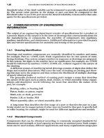
Seal rings
of the
O-ring type
are
used
as
both static
and
dynamic seals. Static seals
serve
the
same purpose
as
gaskets; that
is,
they provide
a
seal between
two
members
that
are not
intended
to
undergo relative motion. Dynamic seals, however,
are
used
where rotating
or
reciprocating motion
is
intended
to
occur.
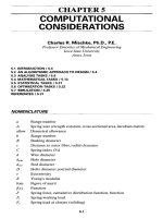
O-rings
are
molded
to the
size
of the
elastomeric material
with
a
circular cross
section,
as
shown
in
Fig.
17.1«.
The
size
is
designated
by the
cross-sectional diameter
w
and the
nominal inside diameter (ID).
The
standard sizes specified
in SAE
J120a
are
summarized
in
Table
17.!.The
first
size number
in a
group
is
associated
with
the
minimum
inside diameter,
and the
last size number
is
associated
with
the
maximum
inside diameter. Some manufacturers provide additional sizes that extend
the
range
of
inside diameters
for a
particular cross-section size.
The
nominal inside diameters
were selected
to
provide dynamic seals
in
cylinder bores dimensioned
in
inches
and
common
fractions
of
inches.
Either
SAE
Jl2Oa
or
manufacturers' recommendations
should
be
consulted
to
obtain
the
recommended compression
of the
cross section.
The
compression
is
different
for
static
and
dynamic applications.
The
rectangular-section ring
in
Fig.
17.Ib
is
manufactured
by
cutting lengths
from
a
tube
of
molded material.
The
standard sizes listed
in SAE
J120a
are
summarized
in
Table 17.2.
The
first
size number
in a
group
is
associated with
the
minimum inside
diameter,
and the
last size number
is
associated with
the
maximum inside diameter.
Rectangular-section rings
are
suitable
for
static applications
with
pressures
up to
1500
psi
[10.3
newtons
per
square millimeter (N/mm
2
)].
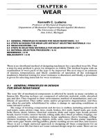
The
standard shape
of
groove
for
sealing rings
is
shown
in
Fig.
17.2.
The
actual
groove dimensions depend
on the
type
and
size
of the
seal ring cross section
and the
nature
of the
application. Recommended groove dimensions
are
provided
in SAE
J120a
and in the
manufacturers' literature. Because elastomeric materials
are
almost
incompressible,
it is
necessary
to
provide
sufficient
volume
for the
seal ring
in the
groove.
The
recommended groove dimensions
do so.
For
static seals,
a
finish
on
surfaces
contacted
by the
seal ring that
is
rougher than
32
uin
(0.8
um) may
lead
to
leakage. Because rough
finishes
accelerate seal wear
in
dynamic
seals,
a
surface
finish
of 5 to 16 uin
(0.13
to 0.4 um) is
preferred. Friction
is
FIGURE
17.1
Seal
rings,
(a)
O-ring;
(b)
rectangular-section
ring.
TABLE
17.1 Standard
Sizes
of
O-Rings
Actual
ID, in
Size
no.
w,
in
Minimum
Maximum
006
to 045
0.070
±
0.003
0.114
±
0.005 3.989
±
0.015
110
to 163
a.
103 ±
0.003 0.362
±
0.005 5.987
±
0.023
210
to 281
0.139
±
0.004 0.734
±
0.006 14.984
±
0.060
325
to 349
0.210
±
0.005 1.475
±
0.010 4.475
±
0.010
425
to 460
0.275
±
0.006 4.475
±
0.015
15.475
±
0.015
ENLARGED
SECTION
ENLARGED
SECTION
TABLE
17.2
Standard Sizes
of
Rectangular-Section Rings
Actual
ID, in
Size
no.
w,
in
c,
in
Minimum Maximum
R006
to
R045
0.066
±
0.004
0.066
±
0.003
0.114
±
0.005
3.989
±
0.015
Rl 10 to
R163
0.099
±
0.004
0.099
±
0.003
0.362
±
0.005
5.987
±
0.023
R210
to
R281 0.134
±
0.004
0.134
±
0.004
0.734
±
0.006
14.984
±
0.060
R325
to
R349
0.203
±
0.005
0.203
±
0.005
1.475
±
0.010 4.475
±
0.015
R425
to
R460
0.265
±
0.005
0.265
±
0.005
4.475
±0.015
15.475
±
0.030
FIGURE 17.2 Shape
of
groove
for
seal
rings.
reduced
with
the
smoother
finish,
but
surfaces
smoother than
5
uin
(0.13
um)
may
not be
satisfactory
for
reciprocating motion.
A
static seal ring application
in
which
the
joint
is
subject
to
internal pressure only
is
shown
in
Fig.
17.3«.
The
groove design
in
Fig.
Il3b
is for a
joint subject
to
exter-
nal
pressure
or
internal vacuum only.
It is
generally advisable
in
these applications
to use as
large
a
seal ring cross section
as
possible because
the
tolerance
on the
groove depth
is
greater with larger cross sections. This requires less precise machin-
ing
and
tends
to
reduce manufacturing costs.
O-rings
are
also used
as
static seals
for
hydraulic tube
fittings
that
are
screwed
into tapped holes. Recommended machining dimensions
are
provided
in SAE
J514
(June 1993).
Elastomeric sealing
rings are
most commonly made
of
nitrile (Buna
N)
com-
pounds. These compounds
are low in
cost
and are
compatible with alcohol, gasoline,
hydraulic
fluids,
lubricating oils,
and
water. They also
are
suitable
for
temperatures
ranging
from
-67 to
257
0
F
(-55
to
125
0
C).
For
resistance
to
higher temperatures
or
compatibility with other
fluids,
other compounds
are
employed. Among these
compounds
are
butyl, ethylene propylene, neoprene,
fluorocarbon,
silicone,
and
polyurethane.
FIGURE 17.3 Static O-ring
seals,
(a)
Joint subject
to
internal pressure only;
(b)
joint subject
to
external
pressure.
77.2
SEALSFORROTARYMOTION
Seals
are
required
on
rotating
shafts
to
retain working
fluids,
to
retain lubricants,
and
to
exclude dirt.
The
selection
of a
seal type depends
on
fluid
pressure,
shaft
speed,
and
whether
any
leakage
can be
permitted. There
are
many variations
of the
basic
seal types that
are
available
from
various manufacturers.
17.2.1
O-Rings
Attempts
to use
O-rings
as
seals
for
rotating
shafts
have
not
always been successful
because
the
elastomers shrink when heated.
If an
O-ring
is
under tension,
friction
between
the
ring
and the
shaft
generates heat that makes
the
ring shrink. Contrac-
tion
of the
ring creates additional heat,
and
failure
occurs rapidly.
O-rings
have been used
successfully
on
rotating
shafts
when they
are
installed
under compression
by
using
a
smaller-than-normal
groove diameter
in the
housing.
Satisfactory
life
can
then
be
obtained
at
shaft
speeds
up to 750
feet
per
minute
(ft/min)
[3.8 meters
per
second (m/s)]
and
sealed pressures
up to 200 psi
(1.38
N/mm
2
).
Recommended O-ring cross sections
are
0.139
in
(3.53
mm) for
speeds
up
to 400
ft/min
(2.0 m/s), 0.103
in
(2.62
mm) for
speeds
from
400 to 600
ft/min
(2.0
to
3.0
m/s),
and
0.070
in
(1.78
mm) for
speeds exceeding
600
ft/min
(3.0 m/s)
[17.1].
17.2.2
Radial
Lip
Seals
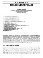
A
section through
a
radial
lip
seal
is
shown
in
Fig.
17.4.
This type
is
used primarily
for
retention
of
lubricants
and
exclusion
of
dirt.
It is
suited
for
conditions
of low
lubri-
cant pressure, moderate
shaft
speeds,
less-than-severe
environmental
conditions,
DIA. EQUALS O-RING OUTSIDE DIA.
DIA. EQUALS O-RING INSIDE DIA.
and
situations where slight leakage
may be
permitted. Radial
lip
seals
are
compact,
effective,
inexpensive,
and
easily installed.
The
outer
case
is
held
in the
bearing housing
by an
interference fit.
The
garter
spring
provides
a
uniform
radial
force
to
maintain contact between
the
elastomeric
sealing lips
and the
shaft.
Lubricant leakage
is
reduced when hydrodynamic sealing
lips
are
used. Such lips have very shallow grooves molded into
the
primary sealing
lip
to
pump lubricant
out of the
contact area. Hydrodynamic sealing lips
are
manu-
factured
for
rotation
in one
direction only
or for
rotation
in
either direction.
Sealing lips
are
most commonly made
of
nitrile (Buna
N)
rubber compounds
because
of
their compatibility with greases, lubricating oils,
and
hydraulic
fluids.
The
nitrile compounds have
poor
to
fair
compatibility with extreme-pressure (EP) addi-
tives
used
in
some gear lubricants.
A
polyacrylate
or
fluoroelastomer
compound
is a
better
choice with
EP
lubricants.
Radial
lip
seal terminology
is
presented
in SAE
Jill
(Jun. 88),
and
recommen-
dations
for
applications
are
made
in SAE
J946 (Oct. 91).
One of the
purposes
of the
secondary sealing
lip
shown
in
Fig. 17.4
is to
exclude dust. That lip, however, leads
to
higher seal temperatures because
of the
additional
friction,
and the
higher tempera-
tures lead
to
earlier seal
failure.
Dual
lip
seals
are not
recommended
for
shaft
speeds
exceeding
150
ft/min
(0.76 m/s)
[17.2].
A
minimum hardness
of
Rockwell
C 30 is
recommended
for the
portions
of
shafts
that contact
the
sealing lips
in
order
to
prevent scoring
of the
shaft.
If the
shaft
may be
damaged
in
handling,
a
minimum hardness
of
Rockwell
C 45
will
pro-
vide
protection
against damage.
A
hard surface
can be
provided
for
soft
shafts
by
use of a
hardened wear sleeve
of
thin steel that
is
held
in
place
by an
interfer-
ence fit.
Radial
lip
seals
function
best with
carbon-,
alloy-,
or
stainless-steel
shafts
or
nickel-plated surfaces.
Use
with aluminum alloys, brass, bronze, magnesium, zinc,
or
similar
metals
is not
recommended.
Shaft
surface
texture should
be in the
range
of 10
to 20
jiin
(0.25
to
0.50
um).
This condition
can
best
be met by
plunge grinding.
This type
of
seal
is
limited
to
sealing pressures
of 3
psig (0.02 N/mm
2
gauge)
at
shaft
speeds
exceeding 2000
ft/min
(10.2 m/s)
and 7
psig (0.05
N/mm
2
gauge)
at
speeds
up to
1000
ft/min
(5.1 m/s). When pressures exceed these limits,
a
mechanical
face
seal
is
preferable.
OPTIONAL
INNER
CASE
GARTER
SPRING
OUTER
CASE
OPTIONAL
SECONDARY
SEALING
LIP
PRIMARY
SEALING
LIP
FIGURE 17.4 Cross section
of
radial
lip
seal.
17.2.3
Face
Seals
Whereas
a
radial
lip
seal contacts
the
shaft
circumference,
a
face
seal acts against
a
surface
perpendicular
to the
shaft
axis.
The
seal
may be
mounted
in a
housing
and
seal against
a
shoulder
or
collar
on the
shaft.
The
seal also
may be
mounted
on the
shaft
and
seal against
a
surface
on the
housing. Some elastomeric face-sealing ele-
ments
are
loaded
by
mechanical springs, whereas others
are
not.
Elastomeric
face
seals (Fig.
11.Sa)
are
used
to
retain lubricants.
For
high-speed
applications,
the
lubricant should
be on the
side where
centrifugal
force throws
the
lubricant into
the
sealing
area.
These
seals have
the
disadvantage
of
requiring rather
precise location with respect
to the
sealing
surface
in
order
to
provide
the
proper
force
on the
seal.
The
sealing
surface
must
be flat and
smooth, with
a
surface
finish
of
10 to 20
uin
(0.25
to
0.50
um).
Less rigid control
of
surface
flatness is
required
for
low
speeds.
Mechanical
face
seals
are
used
in
situations where
a
radial
lip
seal
or
elastomeric
face
seal
will
not be
satisfactory.
Abrasive conditions, such
as
those encountered
by
earth-moving
machinery
and
mining machinery,
may
dictate
the use of a
mechanical
face
seal.
A
mechanical seal
is
frequently
used
in the
automotive coolant pump (Fig.
17.5/?),
in
which
the
pressure
is
relatively low.
Here,
the
stationary spring-loaded seal
ring contacts
a flat
surface
on the
rotor.
If
the
seal
in
Fig.
17.5/?
were used with high-pressure
fluid,
a
high axial sealing
force
would result. Friction between
the
rotor
and
stator could possibly cause over-
heating
of the
seal elements. Consequently,
a
balanced mechanical
face
seal, such
as
in
Fig.
17.5c,
is
used
for
higher pressures.
These
seals
are
proportioned
so
that much
of
the
force
due to
pressure
is
balanced. This leaves
a
small
net
force
to
provide con-
tact
between rotor
and
stator.
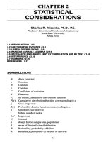
Another
type
of
face
seal, Fig. 17.6,
is
used
to
seal lubricants
in
rotating elements
of
machines that operate
in
environments where water, mud,
or
dust must
be
excluded.
The
seal consists
of two
hardened steel rings with lapped sealing surfaces
that
are
forced together
by
surrounding elastomeric rings.
The
seal surfaces
are
tapered
so
that
the
point
of
contact moves inward
as
wear occurs.
The
seal rings
do
not
contact
the
shaft
that they surround; instead,
one
seal ring
is
driven
by the
rotat-
ing
component through
the
elastomeric ring.
17.2.4
Metal Sealing
Rings
Cast-iron
sealing rings
are
used
in
hydraulic applications where
oil
must
be
intro-
duced through
a
rotating
shaft
(Fig.
17.7).
A
typical application
is to
operate
a
clutch
in an
automatic transmission
for a
motor vehicle. Ring cross-sectional dimensions
are
similar
to
those
for
engine
piston
rings of the
same outside diameter. Informa-
tion
on
designing
to
accommodate these rings
is
provided
in SAE
J281 (Sept. 1980)
and
SAE
J1236 (Apr. 1980).
17.2.5
Compression
Packings
The
stuffing
box
(Fig. 17.8)
is
used
to
seal
fluids
under pressure with either rotating
or
reciprocating
shafts.
Sealing between
the
packing
and the
shaft
occurs
as a
result
of
axial movement
of the
gland when
the
nuts
are
tightened. Friction between
the
packing
and the
shaft
causes wear,
and so
periodic tightening
of the
nuts
is
required.
FIGURE
17.6 Cross section
of a
face
seal
for
severe operating
environments.
FIGURE
17.5 Face
seals,
(a)
Housing-mounted elastomeric seal;
(b)
mechanical seal
for
engine coolant pump;
(c)
balanced mechanical seal.
SEALING AREA
OIL
STATOR
ROTOR
SEALING AREA
,SEALING
AREA
ROTOR
STATOR-
SPRING
FIGURE 17.8
Stuffing
box for a
rotating
shaft.
Packing
material
is
usually obtained
in
straight lengths
of
square
or
rectangular
cross section. Pieces
are cut off and
formed into rings that
fit the
stuffing
box.
The
choice
of
packing material depends
on the fluid to be
sealed. Available packing
materials
include
artificial
fibers,
asbestos, cotton, graphite, jute, leather,
and
metals.
The
metal packings
are
used
for
temperature conditions where
the
other materials
are
inadequate.
The
metal packings
are
formed
from
foil
which
is
compressed into
the
proper packing shape.
In the
design
of
stuffing
boxes, small clearances
are
provided between
the
shaft
and
surrounding parts.
The
small clearances minimize extrusion
of the
packing into
the
clearance spaces.
Valve
stems undergo
a
helical motion rather than
a
rotary motion when
the
valve
is
opened
or
closed. Investigations into
the
prevention
of
valve leakage
and
wear
of
valve
stems resulted
in a
procedure
for
establishing packing dimensions
for
valve
stems
[17.3].
FIGURE 17.7 Metal seal ring application
on a
rotating
shaft.
PACKING
GLAND
SHAFT
17.2.6
Noncontacting
Seals
Frictional losses occur with sealing methods that utilize physical contact between
a
rotating
and a
stationary part. With high rubbing velocities,
friction
losses
may be a
significant
factor. Those losses
can be
eliminated
by
using
a
seal
that
does
not
require physical contact.
A
noncontacting seal, however, cannot prevent leakage
completely, although
it
does reduce
it to a
tolerable level.
One
method
of
achieving
a low
leakage rate
is to
provide
a
very small clearance
between
the
shaft
and the
surrounding housing
or
bushing.
The
longer
the
low-
clearance passage,
the
greater
the
reduction
in
leakage.
A
type
of
noncontacting seal called
the
labyrinth
seal
(Fig. 17.9)
is
used
on
such
machines
as
large blowers
and
steam turbines.
It can be
used
to
retain lubricant
in
the
bearings
or to
seal
the
working
fluid in the
machine. Effectiveness
of the
seal
depends
on
small clearances between
the
seal
and the
shaft.
In
sealing
the
working
fluid, the
small clearances create
a
series
of
pressure drops between
the
working
fluid
and
the
atmosphere.
Labyrinth seals
are
usually made
from
a
relatively
soft
metal such
as
aluminum
or
bronze
so
that
the
shaft
is not
damaged
if
contact between
shaft
and
seal occurs.
The
simplest type
is
shown
in
Fig. 17.9,
but
other types
are
also used.
77.3
SEALSFORRECIPROCATINGMOTION
Some
of the
sealing methods used
for
rotary motion
are
also satisfactory
for
recip-
rocating
motion.
O-rings,
compression packings,
metal
sealing rings,
and
some addi-
tional types
are
used
to
seal reciprocating rods,
shafts,
and
pistons.
17.3.1
O-Rings
The
O-ring
is
used extensively because
of the low
installed cost
and
effectiveness
as
a
seal.
It is
well adapted
to
sealing reciprocating motion
as
well
as for use as a
static
seal. Figure 17.10 shows applications
on a
piston
and
piston
rod as
well
as a
static seal
application. Many such applications
are for
hydraulic cylinders
in
which
the
hydraulic
oil
acts
as the
lubricant
for the
O-rings.
FIGURE 17.9 Labyrinth type
of
noncontacting seal.
FIGURE
17.10 Applications
of
O-rings
as a
static
seal
and as
seals
for
reciprocating
motion.
EXTRUDING
SEAL
—^
Rectangular-section rings
are not
^suited
for
reciprocating motion
and are
used
only
in
static applications.
The
shape
of the
groove
for
circular-section
O-rings
for
sealing reciprocating motion
is
the
same
as
that
for
static applications
(Fig.
17.2).
The
recommended groove
depth
E,
however,
is
slightly
different
for
reciprocating motion. Recommended
dimensions
are
available
in SAE
J120a
and
in the
manufacturers' literature.
An
O-ring must seal
the
clearance
RArimp
OTNP
v
space between
the
reciprocating
and
sta-
BALKUK
KiNt.
—\
tionary parts,
for
example, between
the
piston
and the
cylinder
in
Fig.
17.10.
The
amount
of
clearance that
can be
permit-
ted
depends
on the
pressure
differential
across
the
O-ring
and the
ring hardness.
If
the
clearance
is too
great,
the
O-ring
is
extruded
into
the
clearance space (Fig.
17.110).
The
reciprocating motion then
tears away small pieces
of the
O-ring,
which
results
in a
leaking seal
and
con-
tamination
of the
working
fluid
by the
O-ring particles.
FIGURE
17.11
(a)
Extrusion
of
O-ring into
jhe
pressure limitations
of
O-rings
clearance
space
due
to
pressure,
(b)
Use
of
^
be
overcome
b
the
use
of
backup
backup
ring
to
prevent extrusion.
.
,_.
*~+«,\
.,
i
•
<•>
.
F
F
rings
(Fig.
17.116)
or
other devices that
prevent O-ring extrusion. Backup rings
are
made
from
leather, plastics,
or
metal.
The
metal rings
are
split like
a
piston ring
for
radial compression during assembly into
the
cylinder.
PISTON
SEAL
STATIC
SEAL
ROD
SEAL
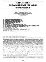
Recommendations
on the
combination
of
clearance
and
pressure
for
which
backup
rings
are
required vary
to
some extent among
the
various O-ring suppliers.
Figure 17.12 provides
one
such recommendation
[17.4].
In
this
figure,
if the
combi-
nation
of fluid
pressure
and
maximum
gap
falls
to the
right
of a
hardness curve,
backup rings
are
required.
If a
piston
or rod can be
forced
to one
side
of the
bore,
the
maximum
gap is the
difference
between
the two
diameters.
If,
however,
the
radial
position
of the
piston
or rod is
restrained,
as by
bearings,
the
radial clearance
is the
maximum gap.
Both
the
compression
of the
O-ring cross section
to
effect
a
seal
and fluid
pres-
sure acting
on the
seal cause
friction
forces
that oppose reciprocating motion. Infor-
mation
for
estimating friction factors
is
provided
in
Fig. 17.13
[17.4].
The
friction
factor
due to
compression
of the
cross section
can be
obtained
from
Fig.
17.13«.
The
seal compression
is
expressed
as a
percentage
of the
O-ring cross section.
The
fric-
tion factor
is
multiplied
by the
circumference
of the
surface
where relative motion
occurs
to
obtain
the
friction force.
For a
piston,
the
circumference
of the
cylinder
bore
is
used;
for a
piston rod,
the rod
circumference applies.
The
friction
factor
for
pressure
differential
across
the
O-ring
is
obtained
from
Fig.
17.136.
That factor
is
multiplied
by the
projected
area
of the
O-ring
to
obtain
the
friction
force.
For an
O-ring
in a
piston,
the
projected area
is the
product
of the
diam-
eter
of the
ring cross section
and the
circumference
of the
cylinder bore.
The
total
estimated
friction
force
is the sum of the
friction
forces
due to
compression
and fluid
pressure.
MAXIMUM
GAP,
in
FIGURE
17.12
Extrusion
limits
for
O-rings.
(From Ref.
[17.4].)
FLUID
PRESSURE,
kpsi
(b)
FIGURE
17.13 O-ring
friction
factors
due to (a)
compression
of the
cross section
and (b)
fluid
pressure.
(From
Ref.
[17.4].)
SEAL
COMPRESSION,
%
(a)
The
finish
of
rubbing
surfaces
should
be 8 to 16
uin
(0.2
to 0.4
jum)
for
O-rings
with
a
hardness
of 70
Shore
A. For
rougher
surfaces,
a
higher O-ring hardness should
be
used
to
ensure reasonable
life.
O-rings
may be
damaged
if
they
are
forced over sharp corners during assembly.
The
addition
of
chamfers
to
corners
is an
inexpensive method
of
reducing damage.
Serious damage
to
O-rings occurs
if
they
are
forced
to
pass over
a
hole
in a
cylinder
wall
while under pressure.
If
this occurs,
the
O-ring expands into
the
hole
and
must
later
be
forced back into
the
groove. This action tends
to
shear pieces
off
the
ring
and
thus destroy
its
ability
to
seal.
17.3.2
Lip
Packings
Cup
packings,
U-seals,
V-ring packings,
and
other
forms
of lip
packings
are
used pri-
marily
to
seal reciprocating motion.
The
packing material
is
usually leather, solid
rubber,
or
fabric-reinforced rubber, although other compounds
are
available
for
dif-
ficult
applications.
An
advantage
of
leather packings
is a low
coefficient
of
friction,
on the
order
of
0.006
to
0.008 depending
on the
tanning process.
Low
friction
increases
the
life
of a
packing because less heat
is
generated.
Cup
packings (Fig.
17.14)
were
one of the
first
types
of
piston seals
for
hydraulic
and
pneumatic applications.
The fluid
pressure expands
the cup
outward against
the
cylinder wall
and
thus seals
the
piston
in the
cylinder. This action requires that
a
double-acting cylinder have
two
packings
in
order
to
seal
the
pressure
in
both
directions
of
operation.
The
inner portion
of the
piston
in
Fig. 17.14
is a
boss
to
pre-
vent excessive tightening
of the
washer against
the
cup.
If the cup is
crushed against
the
piston, good sealing will
not be
obtained.
Figure 17.15 shows elastomeric U-seals
on a
double-acting piston. This type
of
seal
is
also used
on
piston rods. They have approximately
the
same pressure limita-
tions
as
O-rings,
and
backup rings
are
required
for
higher pressures. When
a
U-seal
is
made
of
leather,
a
filler
is
required between
the
lips
to
prevent collapse
of the
seal.
FIGURE 17.14
Cup
packing
for
single-acting
cylinder.
FIGURE 17.15
U-seals
for a
double-acting piston.
Rod
scrapers
are
used
on
piston rods
of
hydraulic cylinders that
are
exposed
to
harsh
environments.
The
purpose
is to
exclude mud, dust,
and ice
from
the
cylinder.
A
typical
rod
scraper
is
composed
of a
polyurethane element bonded
to a
metal
shell
which
is
pressed into
the end cap of the
cylinder. Molybdenum disulfide
is
sometimes added
to the
polyurethane
to
reduce friction.
A rod
scraper added
to the
end cap of a
cylinder
is
shown
in
Fig.
17.16.
The
sealing
lip is
pointed outward
to
remove foreign material when
the
piston
rod is
retracted.
The
chief
use of the
V-ring packing (Fig.
17.17)
is for
sealing piston rods
or
recip-
rocating
shafts,
although
it can
also
be
used
to
seal pistons.
The
ability
to
seal
fluids
under pressure depends
on the
type
of
packing material
and
number
of
packings
used.
The
V-ring packing
is
considered superior
to
other
lip
types
for
sealing high
pressures, especially above
50 000 psi
(345
N/mm
2
).
The V
shape
of the
packing
is
obtained through
the
adapters that support
the
rings.
Fluid pressure then expands
the
packing against
the
shaft
and
housing
to
seal
FIGURE
17.16
Rod
scraper
on
piston rod.
FIGURE
17.17 V-ring packing
for a
reciprocating
shaft.
the fluid. A
continuous packing provides
better
sealing than
a
series
of
split rings,
although
the
latter
are
easier
to
install
and
remove.
17.3.3
Piston
Rings
Piston rings
for
automotive engine applications
are
made
of
gray cast iron.
The
rings
are
used
to
seal gases
in the
cylinder
and to
restrict
oil to the
crankcase.
Piston rings must
be
split
for
assembly over
the
piston. This requires shaping
the
ring
so
that
it
will provide
a
uniform radial force against
the
cylinder wall. Piston ring
manufacturers
have developed methods
of
attaining this objective.
REFERENCES
17.1 Leonard
J.
Martini, "Sealing Rotary
Shafts
with
O-Rings,"
Machine
Design,
May 26,
1977,pp.97-99.
17.2 Bert Robins, "Radial
Lip
Seals—Are
Two Too
Many?" Power
Transmission
Design,
October 1982,
pp.
73,74.
17.3
L.
I.
Ezekoye
and J. A.
George,
"Valve
Packings that
Don't
Leak,"
Machine
Design,
Jan.
20,
1977,
pp.
142,143.
17.4
Wes J.
Ratelle,
"Seal
Selection: Beyond Standard Practice," Machine Design, Jan.
20,
1977,
pp.
133-137.
BOLTED
GLAND WITH
INTEGRAL
FEMALE ADAPTER
PACKING
SCREW-TYPE GLAND
FEMALE
ADAPTER
MALE
ADAPTER