Sổ tay tiêu chuẩn thiết kế máy P24 doc
Bạn đang xem bản rút gọn của tài liệu. Xem và tải ngay bản đầy đủ của tài liệu tại đây (462.18 KB, 13 trang )
CHAPTER
20
POWER
SCREWS
Rudolph
J.
Eggert,
Ph.D.,
RE.
Associate
Professor
of
Mechanical
Engineering
University
of
Idaho
Boise,
Idaho
20.1 INTRODUCTION
/
20.2
20.2 KINEMATICS
/
20.3
20.3 MECHANICS
/
20.6
20.4 BUCKLING
AND
DEFLECTION
/
20.8
20.5 STRESSES
/
20.9
20.6
BALL
SCREWS/20.10
20.7 OTHER DESIGN CONSIDERATIONS
/20.12
REFERENCES
/
20.13
LIST
OF
SYMBOLS
A
Area
A(t)
Screw translation acceleration
C
End
condition constant
d
Major
diameter
d
c
Collar diameter
d
m
Mean diameter
d
r
Root
or
minor diameter
E
Modulus
of
elasticity
F
Load
force
F
0
Critical load
force
G
Shear modulus
h
Height
of
engaged threads
/
Second moment
of
area
J
Polar second moment
of
area
k
Radius
of
gyration
L
Thread lead
L
c
Column length
n
Angular speed, r/min
n
s
Number
of
thread starts
N
6
Number
of
engaged threads
P
1
Basic load rating
p
Thread pitch
Sy
Yield strength
T
c
Collar
friction
torque
Ti
Basic static thrust capacity
T
R
Raising torque
T
L
Lowering torque
t
Time
V(f)
Screw translation speed
w
Thread width
at
root
W
1
Input work
W
0
Output work
a
Flank angle
Oi
n
Normalized
flank
angle
P
Thread geometry parameter
Ax
Screw translation
A0
Screw rotation
T|
Efficiency
X
Lead angle
|i
r
Coefficient
of
thread
friction
(i
c
Coefficient
of
collar friction
a
Normal stress
a'
von
Mises stress
1
Shear stress
¥
Helix angle
20.1
INTRODUCTION
Power screws convert
the
input rotation
of an
applied torque
to the
output transla-
tion
of an
axial force. They
find
use in
machines such
as
universal tensile testing
machines,
machine tools, automotive jacks, vises, aircraft
flap
extenders, trench
braces, linear actuators, adjustable
floor
posts, micrometers,
and
C-clamps.
The
mechanical
advantage inherent
in the
screw
is
exploited
to
produce large axial forces
in
response
to
small torques. Typical design considerations, discussed
in the
following
sections, include kinematics, mechanics, buckling
and
deflection,
and
stresses.
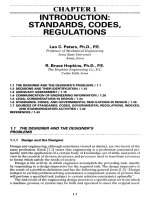
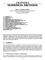
Two
principal categories
of
power screws
are
machine screws
and
recirculating-
ball
screws.
An
example
of a
machine screw
is
shown
in
Fig.
20.1.
The
screw threads
are
typically formed
by
thread rolling, which results
in
high surface hardness, high
strength,
and
superior surface
finish.
Since high thread friction
can
cause self-locking
when
the
applied torque
is
removed, protective brakes
or
stops
to
hold
the
load
are
usually
not
required.
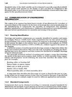
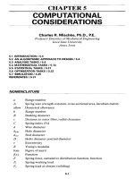
Three thread forms that
are
often
used
are the
Acme
thread,
the
square
thread,
and the
buttress
thread.
As
shown
in
Fig. 20.2,
the
Acme thread
and
the
square thread exhibit symmetric
leading
and
trailing
flank
angles,
and
consequently
equal strength
in
raising
and
lowering.
The
Acme thread
is
inher-
ently
stronger than
the
square thread
because
of the
larger thread width
at the
root
or
minor diameter.
The
general-
purpose Acme thread
has a
14M-degree
flank
angle
and is
manufactured
in a
number
of
standard diameter sizes
and
thread spacings, given
in
Table
20.1.
The
buttress thread
is
proportionately wider
at the
root than
the
Acme thread
and is
typically
loaded
on the
7-degree
flank
rather than
the
45-degree
flank. See
Refs.
[20.1], [20.2], [20.3],
and
[20.4]
for
complete details
of
each thread form.
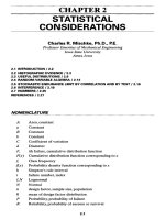
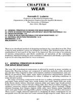
Ball
screws recirculate ball bearings
between
the
screw
rod and the
nut,
as
shown
in
Fig. 20.3.
The
resulting rolling
friction
is
significantly less than
the
slid-
ing
friction
of the
machine screw type.
Therefore
less input torque
and
power
are
needed. However, motor brakes
or
screw
stops
are
usually required
to
pre-
vent ball screws
from
self-lowering
or
overhauling.
FIGURE 20.1
Power
screw assembly using
rolled
thread
load
screw driven
by
worm
shaft
and
gear nut. (Simplex
Uni-Lift
catalog
UC-IOl,
Templeton,
Kenly
&
Co., Inc., Broadview,
III,
with
permission.)
20.2 KINEMATICS
The
primary function
or
design requirement
of a
power screw
is to
move
an
axial
load
F
through
a
specified
linear distance, called
the
travel.
As a
single-degree-of-
freedom
mechanism, screw travel
is
constrained between
the
fully
extended
position
jc
max
and the
closed
or
retracted
position
;c
min
.The
output
range
of
motion,
therefore,
is
x
max
-
*min-
As the
input torque
T is
applied through
an
angle
of
rotation
A0, the
screw
travels
AJC
in
proportion
to the
screw lead
L or
total number
of
screw turns
N
t
as
follows:
Ax
=
L^
=
LN,
(20.1)
In
addition
to
range
of
motion specifications, other kinematic requirements
may be
prescribed, such
as
velocity
or
acceleration.
The
linear screw speed
K
in/min,
is
obtained
for a
constant angular speed
of n,
r/min,
as
V = nL
(20.2)
FIGURE
20.2 Basic thread
forms,
(a)
Square;
(b)
general-purpose Acme;
(c)
buttress.
The
stub Acme thread height
is
0.3/?.
TABLE
20.1
Standard Thread
Sizes
for
Acme Thread
Form
t
Size
D, in
Threads
per
inch
n
/4
16
5
A
16,14
3
/
8
16,14,12,10
7
X
6
16,14,12,10
1
A
16,14,12,10,8
5
/8
16,14,12,10,8
%
16,14,12,10,8,6
7
/
8
14,12,10,8,6,5
1
14,12,10,8,6,5
1/8
12,10,8,6,5,4
VA
12,10,8,6,5,4
I
3
X
8
10,8,6,5,4
1/2
10,8,6,5,4,3
l
3
/
4
10,8,6,4,4,3,2/2
2
8,6,5,4,3,2/,
2
2/4
6,5,4,3,2/2,2
2/
2
5,4,3,2/2,2
2
3
/
4
4,3,2/2,2
3
4,3,2/2,2,1/2,1/
3/2
4,3,2/2,2,1/2,1/3,1
4
4,3,2/,
2,1/2,1/,
1
4/2
3,
2/2,
2,
1/2,
1/3,
1
5
3,2/2,2,1/2,1/3,1
f
The
preferred
size
is
shown
in
boldface.
FIGURE
20.3
Ball screw assembly.
(Saginaw
Steering Gear
Division,
General
Motors
Corporation.)
The
input speed
may
vary with respect
to
time
t,
resulting
in a
proportional change
in
output speed according
to
V(O=J(O=^e(O
(20.3)
Similarly,
the
linear
and
angular accelerations
of the
load screw
are
related
as
follows:
A(t)
=X(t)=
^0(O
(20.4)
Inertia
forces
and
torques
are
often
neglected
for
screw systems which have small
accelerations
or
masses.
If the
screw accelerates
a
large mass, however,
or if a
nomi-
nal
mass
is
accelerated
quickly,
then inertia forces
and
torques should
be
analyzed.
The
total required input torque
is
obtained
by
superposing
the
static equilibrium
torque,
the
torque required
to
accelerate
the
load,
and the
inertia torque
of the
screw
rod
itself.
The
inertia torque
of the
screw
is
sometimes
significant
for
high-
speed linear actuators.
And
lastly,
impacts resulting
from
jerks
can be
ana-
lyzed
using strain-energy methods
or
finite-element
methods.
20.3 MECHANICS
Under static equilibrium conditions,
the
screw
rotates
at a
constant speed
in
response
to the
input torque
T
shown
in
the
free-body diagram
of
Fig. 20.4.
In
addition,
the
load force
F,
normal force
N,
and
sliding
friction
force
F
f
act on the
FIGURE
20.4 Free-body
diagram
of
load
§crew
^
friction
fofce
Qp
p
oses
fda
_
screw
*
tive motion. Therefore,
the
direction
of
the
friction force
F
f
will reverse when
the
screw translates
in the
direction
of
the
load rather than against
it.
The
torques required
to
raise
the
load
T
R
(i.e., move
the
screw
in the
direction opposing
the
load)
and to
lower
the
load
T
L
are
FcL/nn,d
m
+
Lp\
TR
~
2
(ndJ-toL)
(2
°'
5)
Fd
m
/«M«-
Lb
\
,
,
T
<-
=
2
Ud
m
p
+
n,LJ
(2
°'
6)
where
d
m
=
d-p/2
L =
pn
s
tan
K
=
——
nd
m
tan
OC
n
= tan a cos K
P
= cos
CC
n
(P = 1 for
square threads)
The
thread geometry parameter
p
includes
the
effect
of the
flank
angle
a as it is
pro-
jected
normal
to the
thread
and as a
function
of the
lead angle.
For
general-purpose
single-start
Acme threads,
a is
14.5 degrees
and P is
approximately 0.968, varying
less
than
1
percent
for
diameters ranging
from
1
A
in to 5 in and
thread spacing rang-
ing
from
2 to 16
threads
per
inch.
For
square threads,
P =
I.
In
many applications,
the
load slides relative
to a
collar, thereby requiring
an
additional
input torque
T
0
:
T
0
^
(20.7)
Ball
and
tapered-roller thrust bearings
can be
used
to
reduce
the
collar torque.
The
starting torque
is
obtained
by
substituting
the
static
coefficients
of
friction
into
the
above equations. Since
the
sliding coefficient
of
friction
is
roughly
25
per-
cent less than
the
static coefficient,
the
running torque
is
somewhat less than
the
starting torque.
For
precise
values
of
friction coefficients, specific data should
be
obtained
from
the
published technical literature
and
verified
by
experiment.
Power screws
can be
self-locking
when
the
coefficient
of
friction
is
high
or the
lead
is
small,
so
that
n[i
t
d
m
> L or,
equivalently,
ju,
> tan
X.
When this condition
is not
met,
the
screw will
self-lower
or
overhaul unless
an
opposing torque
is
applied.
A
measure
of
screw
efficiency
T]
can be
formulated
to
compare
the
work output
W
0
with
the
work input
W
1
:
n
=
f^=f^
(20.8)
where
T is the
total
screw
and
collar
torque.
Similarly,
for
one
revolution
or
2n
radi-
ans
and
screw translation
L,
T
1
=
U
(20.9)
Screw manufacturers often list output travel
speed
V, in
in/min,
as a
function
of
required motor
torque
Tin
lbf
•
in,
operating
at n
r/min,
to
lift
the
rated capacity
F, in
lbf.
The
actual
efficiency
for
these
data
is
therefore
FV
^
T^T
(
20
'
10
>
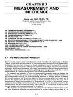
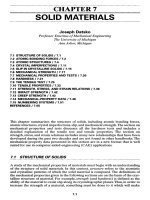
Efficiency
of a
square-threaded power screw with respect
to
lead angle
X,
as
shown
in
Fig. 20.5,
is
obtained
from
""££=!
<
2
»'»>
Lead
Angle
(degrees)
FIGURE
20.5 Screw
efficiency
r|
versus
thread lead angle
X.
Note
the
importance
of
proper
lubrication.
For
example,
for
X
= 10
degrees
and
|i
=
0.05,
T)
is
over
75
percent. However,
as the
lubricant becomes contaminated
with
dirt
and
dust
or
chemically breaks down over time,
the
friction
coefficient
can
increase
to
|i
=
0.30, resulting
in an
efficiency
r|
=
35
percent,
thereby doubling
the
torque, horsepower,
and
electricity requirements.
20.4
BUCKLINGANDDEFLECTION
Power
screws subjected
to
compressive loads
may
buckle.
The
Euler
formula
can be
used
to
estimate
the
critical load
F
0
at
which buckling
will
occur
for
relatively long
screws
of
column length
L
0
and
second moment
of
area
I=
nd
4
r
/64
as
, ^)
«**>
where
C is the
theoretical end-condition constant
for
various cases given
in
Table
20.2. Note that
the
critical buckling load
F
0
should
be
reduced
by an
appropriate
load
factor
of
safety
as
conditions warrant.
See
Chap.
15 for an
illustration
of
various
end
conditions
and
effective
length
factor
K,
which
is
directly related
to the
end-
condition constant
by C =
l/K
2
.
A
column
of
length
L
c
and
radius
of
gyration
k is
considered long when
its
slen-
derness ratio
LJk is
larger than
the
critical slenderness ratio:
¥>(¥]
(20.13)
fe
\
k
/critical
V
'
^PfT
The
radius
of
gyration
k,
cross-sectional area
A, and
second moment
of
area
I are
related
by
/=Ak
2
,
simplifying
the
above expression
to
L
c
1
/2n
2
CE\
y2
/n<|rx
^inr/
(2ai5)
For a
steel screw whose yield strength
is 60 000 psi and
whose end-condition constant
is
1.0,
the
critical slenderness ratio
is
about 100,
and
LJd
r
is
about
25. For
steels whose
slenderness ratio
is
less than critical,
the
Johnson parabolic relation
can be
used:
£-*-<s(^)'
<2U6)
TABLE
20.2
Buckling
End-Condition
Constants
End
condition
C
Fixed-free
V*
Rounded-rounded
1
Fixed-rounded
2
Fixed-fixed
4
which
can be
solved
for a
circular cross section
of
minor diameter
d
r
as
W^t
+
M
(2017)
The
load should
be
externally guided
for
long travels
to
prevent eccentric loading.
Axial compression
or
extension
5 can be
approximated
by
FT
4FT
s
=^=St
<
20
-
18
)
And
similarly, angle
of
twist
c|>,
in
radians,
can be
approximated
by
TL
0
32TL
C
*
=
TG=^G
(2019)
20.5
STRESSES
Using
St.
Venants' principle,
the
nominal
shear
and
normal
stresses
for
cross sections
of
the
screw
rod
away
from
the
immediate vicinity
of the
load
application
may be
approximated
by
'"7-^
00»
""
=
^
=
5
<2tm)
Failure
due to
yielding
can be
estimated
by the
ratio
of
S
y
to an
equivalent,
von
Mises stress
a'
obtained
from
//
4F
V
f!6T\
2
4 Il
F\
2
I
T\
2
o
'=Vfe)
+3
fe)
=
^vu)
+48
fe)
(2a22)
The
nominal
bearing
stress
a/,
on a nut or
screw depends
on the
number
of
engaged threads
N
e
=
hip
of
pitch
p and
engaged thickness
h and is
obtained
from
°*
= A
F
=
(J?
#\
&}
(
20
-
23
)
^projected
K
(d
2
-
d?)
\k
J
Threads
may
also shear
or
strip
off the
screw
or nut
because
of the
load
force,
which
is
approximately parabolically distributed over
the
cylindrical
surface
area
Acyi.
The
area depends
on the
width
w
of the
thread
at the
root
and the
number
of
engaged threads
N
e
according
to
A^
=
ndwN
e
.
The
maximum shear stress
is
esti-
mated
by
*
=
TT~
(
20
-
24
>
Z,
Slcyl
For
square threads such that
w
=p/2,
the
maximum shear stress
for the nut
thread
is
^
(
20
-
25
)
To
obtain
the
shear stress
for the
screw thread, substitute
d
r
for d.
Since
d
r
is
slightly
less than
d, the
stripping shear stress
for the
screw
is
somewhat larger.
Note that
the
load
flows
from
the
point
of
load application through
the
thread
geometry
to the
screw
rod.
Because
of the
nonlinear strains induced
in the
threads
at
the
point
of
load application, each thread carries
a
disproportionate share
of the
load.
A
detailed analytical approach such
as
finite-element methods, backed
up by
experiments,
is
recommended
for
more accurate estimates
of the
above stresses
and of
other stresses, such
as a
thread bending stress
and
hoop
stress induced
in
the
nut.
20.6 BALLSCREWS
The
design
of
ball screw assemblies
is
similar
to
that
of
machine screw systems. Kine-
matic
considerations such
as
screw
or nut
travel, velocity,
and
acceleration
can be
estimated
following
Sec. 20.2.
Similarly input torque, power,
and
efficiency
can be
approximated using formulas
from
Sec. 20.3.
Critical buckling loads
can be
esti-
mated using
Eq.
(20.12)
or
(20.16). Also, nominal shear
and
normal stresses
of the
ball
screw
shaft
(or
rod)
can be
estimated using
Eqs.
(20.20)
and
(20.21).
Design
for
strength, however,
is
typically completed using
a
catalog selection
pro-
cedure rather than analytical
stress-versus-strength
analysis. Ball screw manufactur-
ers
usually list static
and
dynamic load capacities
for a
variety
of
screw
shaft
(rod)
diameters,
ball diameters,
and
screw leads;
an
example
is
shown
in
Table 20.3.
The
static
capacity
for
basic
static
thrust
capacity
T
1
,
lbf,
is the
load which
will
produce
a
ball track deformation
of
0.0001 times
the
ball diameter.
The
dynamic capacity
or
basic
load
rating
P
1
,
lbf,
is the
constant axial load that
a
group
of
ball screw assem-
blies
can
endure
for a
rated
life
of one
million inches
of
screw travel.
The
rated
life
is
the
length
of
travel that
90
percent
of a
group
of
assemblies will complete
or
exceed
before
any
signs
of
fatigue
failure
appear.
The
catalog ratings, developed
from
labo-
ratory
test results, therefore involve
the
effects
of
hertzian contact stresses, manu-
facturing
processes,
and
surface
fatigue
failure.
The
catalog selection process requires choosing
the
appropriate combination
of
screw
diameter, ball diameter,
and
lead,
so
that
the
axial load
F
will
be
sufficiently
less
than
the
basic
static
thrust capacity
or the
basic
load
rating
for the
rated
axial
travel
life.
For a
different
operating travel
life
of X
inches,
the
modified basic load
rating
P
1x
,
lbf,
is
obtained
from
/1O
6
V*
P*
=
P,-hH
(20.26)
\
A
I
An
equivalent load rating
P can be
obtained
for
applications involving loads
P\,P^,
P
3
,
,P
n
that occur
for
C
1
,
C
2
,
C
3
, ,
C
n
percent
of the
life,
respectively:
./C
1
Pj
+
M
+
+^;
r
~V
100
l/u.z/;
For the
custom design
of a
ball screw assembly,
see
Ref.
[20.5], which provides
a
number
of
useful
relations.
TABLE
20.3 Sizes
and
Capacities
of
Ball
Screws
1
Major
diameter,
in
Lead,
in, mm
Ball diameter,
in
Dynamic capacity,
Ib
Static capacity,
Ib
0.750 0.200 0.125
1242
4595
0.250 0.125 1242 4495
0.875 0.200 0.125
1336
5234
0.250 0.125 1336
5234
1.000 0.200 0.125 1418
5973
0.200
f
0.156
1909
7469
0.250 0.125
1418
5973
0.250 0.156 1909
7469
0.250 0.187
— —
0.400
0.125 1418
5973
0.400
0.187
— —
1.250 0.200 0.125
1904
9936
0.20O
1
0.156 2583 12420
0.250 0.125
1904
9936
0.250 0.156 2583 12420
0.250 0.187 3304
15886
1.500 0.200 0.125 2046
11908
0.20O
1
0.156 2786
14881
0.250 0.156 2786
14881
0.250 0.187
3583
18748
0.500 0.156 2786 14881
0.500 0.250
5290
24762
1.500
5
1
0.125 2046
11908
5
0.156 2787
14881
10
0.156 2786
14881
10
0.250
5290
24762
10
0.312 7050 29324
1.750 0.200 0.125
2179
13879
0.200
f
0.156 2968
17341
0.250 0.156 2968 17341
0.250 0.187 3829 20822
0.500 0.187 3829
20882
0.500 0.250
5664
27917
0.500 0.312 7633 33232
2.000 0.200 0.125 2311
15851
0.200
f
0.156
3169
19801
0.250
0.156
3169
19801
0.250 0.187 4033
23172
0.400 0.250 6043
31850
0.500 0.312 8135 39854
5
0.125 2311 15851
5
f
0.156
3169
19801
6
0.156 3169 19801
6
0.187 4033
23172
10
0.250 6043
31850
10
0.312
8135
39854
TABLE
20.3 Sizes
and
Capacities
of
Ball
Screws
1
(Continued)
Major
diameter,
in
Lead,
in, mm
Ball diameter,
in
Dynamic capacity,
Ib
Static capacity,
Ib
2.250 0.250 0.156
3306
22262
0.250 0.187 4266
26684
0.500 0.312
8593
44780
0.500 0.375
10862
53660
2.500
0.200 0.125 2511
19794
0.200 0.156
3134
24436
0.250 0.187 4410
29671
0.400 0.250
6633
39746
0.500 0.312 9015
49701
0.500 0.375
10367
59308
5
0.125 2511
19794
5
f
0.156
3134
24436
10
0.250
6633
39746
10
0.312 9015
49701
3.000 0.250 0.187
4810
35570
0.400 0.250
7125
47632
0.500 0.375
12560
71685
0.660 0.375
12560
71685
10
0.250
7125
47632
10
0.312 9744
58648
3.500 0.500 0.312
10360
69287
0.500 0.375
13377
83514
1.000 0.500 19812
111510
1.000 0.625 26752
139585
4.000 0.500 0.375
14088
95343
1.000
0.500
21066
127 282
f
These values
are not
recommended; consult manufacturer.
Source:
20th Century Machine Company, Sterling Heights,
Mich.,
by
permission.
20.7
OTHERCONSIDERATIONS
A
number
of
other important design factors should also
be
considered. Principal
among
these
is
lubrication. Greases using lithium thickeners with antioxidants
and
EP
additives
are
effective
in
providing acceptable
coefficients
of
sliding
friction
and
corrosion protection.
For
operating environments which expose
the
screw threads
to
dust,
dirt,
or
water,
a
protective boot, made
of a
compatible material,
is
recom-
mended. Maintenance procedures should ensure that
the
screw threads
are
free
of
contaminants
and
have
a
protective
film
of
grease. Operation
at
ambient tempera-
tures
in
excess
of
20O
0
F
requires special lubricants
and
boot materials
as
recom-
mended
by the
manufacturer.
Screw
and nut
threads will wear with use, especially
in
heavy-duty-cycle applica-
tions,
increasing
the
backlash
from
the
as-manufactured allowance.
Use of
adjust-
able split nuts
and
routine inspection
of
thread thickness
is
recommended.
Power screws employing electric motors
are
often
supplied with integral limit
switches
to
control extension
and
retraction.
To
prevent ejection
of the
screw
in
case
of
a
limit switch
failure,
a
stop
nut can be
added.
In
addition,
a
torque-limiting clutch
can
be
integrated
at the
motor
to
prevent equipment damage.
REFERENCES
20.1 ANSI B1.7M-1984 (R1992), "Screw Threads, Nomenclature, Definitions,
and
Letter
Symbols," American Society
of
Mechanical Engineers,
New
York, 1992.
20.2
ANSI
Bl.5-1977,
"Acme
Screw Threads," American Society
of
Mechanical Engineers,
New
York, 1977.
20.3
ANSI
Bl.8-1977,
"Stub Acme Screw Threads," American Society
of
Mechanical Engi-
neers,
New
York, 1977.
20.4
ANSI
Bl.9-1973
(R1979), "Buttress Screw Threads," American Society
of
Mechanical
Engineers,
New
York, 1973.
20.5
ANSI B5.48-1977 (R1988), "Ball Screws," American Society
of
Mechanical Engineers,
New
York, 1977.