Part3: TCP/IP Protocol Suite and IP Addressing pps
Bạn đang xem bản rút gọn của tài liệu. Xem và tải ngay bản đầy đủ của tài liệu tại đây (423.87 KB, 15 trang )
Internal Using in ptithcm 1
Part3. TCP/IP Protocol Suite and
IP Addressing
Computer Network
References:
1. Data- Computer Communication handbook- William
Stallings
2. TCP/IP Illustrated, Volume I - W.R. Stevens
3. CCNA- semester1-2-3-4
1
Table of Content
UDP5
TCP
4
IP Format3
ICMP
3
Internet addresses
2
Introduction to TCP/IP Model
1
INTRODUCTION TO TCP/IP
TCP/IP model development
• The late-60s The Defense Advance Research Projects
Agency (DARPA) originally developed Transmission
Control Protocol/Internet Protocol (TCP/IP) to
interconnect various defense department computer
networks.
• The Internet, an International Wide Area Network,
uses TCP/IP to connect networks across the world.
TCP/IP protocol stack
TCP/IP protocol stack
• Focus on IP
Network level:
•Multiple higher-
layer protocols
to applications
•Multiple lower-
layer protocols
to physical links
•Only IP
protocol at the
network layer.
Cases of Access Network
WAN
LAN to LAN
LAN to WAN
WAN to WAN
Internal Using in ptithcm 2
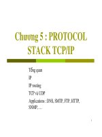
IP Suite: End Hosts vs. Routers
7
HTTP
TCP
IP
Ethernet
interface
HTTP
TCP
IP
Ethernet
interface
IP IP
Ethernet
interface
Ethernet
interface
SONET
interface
SONET
interface
host
host
router
router
HTTP message
TCP segment
IP packet IP packetIP packet
The Network Access Layer
• Provide the ways and means to access to the internal network
(LAN) or external network (WAN)
•To LAN with Ethernet, Tokenring, FDDI
• To WAN with dial-up/PSTN, Frame relay, ADSL/ATM, lease-
line …
• Deals all the details in the OSI physical and data link layers.
– Connectors with electrical, mechanical, procedural and
functional specifications.
– Media access control with
• Data rate, Distances, synchronization
• Frames, physical addressing, flow control, error
control.
• Multiplexing
The internet layer
• IP provide provides an unreliable connectionless best
effort service (also called: “datagram service”).
– Unreliable: IP does not make an attempt to recover
lost packets
– Connectionless: Each packet (“datagram”) is handled
independently. IP is not aware that packets between
hosts may be sent in a logical sequence
– Best effort: IP does not make guarantees on the
service (no throughput guarantee, no delay
guarantee,…)
• Consequences:
– Higher layer protocols have to deal with losses or
with duplicate packets
– Packets may be delivered out-of-sequence
The Transport Layer
• Responsibility
– Provides reliable transport services from the
source host to the destination host (end-to-end)
over networks.
•Concerns
– Segments, data stream, datagram.
– Defines end-to-end connectivity between host
applications.
– Transmission control protocol (TCP) – Connection
oriented
– User datagram protocol (UDP) – Connectionless
Application layer
• Responsibility
– Handles high-level protocols, issues of
representation, encoding, and dialog control, and
assures this data is properly packaged for the
next layer.
•Concerned
– File Transfer ( TFTP, FTP, NFS)
–E-Mail (SMTP)
– Remote Login (Telnet, rlogin)
– Network management (SNMP)
– Name Management (DNS)
Internet layer other protocols
• Internet Control Message Protocol (ICMP)
− Provides control and messaging capabilities.
– IP communication service messages like PING,
TRACEROUTE and ROUTER
• Internet Group Message Protocol (IGMP)
– IP communications based on multicasting (sending
to groups of hosts)
• Address Resolution Protocol (ARP)
− Determines the data link layer address, MAC
address, for known IP addresses.
• Reverse Address Resolution Protocol (RARP)
− Determines IP addresses when the MAC address is
known.
Internal Using in ptithcm 3
• Routing protocols:
– RIP/ RIPng (for IPv6)
– OSPF v2, v3
–BGP
•For security:
– 802.1x
–IPsec
– SSL/ TLS
– SSH
• For QoS control: RSVP…
Internet layer other protocols
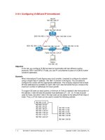
IP Datagram Format
ECN
version
header
length
DS total length (in bytes)
Identification Fragment offset
source IP address
destination IP address
options (0 to 40 bytes)
payload
4 bytes
time-to-live (TTL) protocol header checksum
bit # 0 15 23 24831716
0
M
F
D
F
QoS controlling at transit routers:
¾DS- Differentiated Service / Type-of-Service (TOS)
field.
¾Explicit Congestion Notification to TCP (ECN-2bits)
¾Fragmenting and re-assembly functions using
• total length
•identification
•don’t fragment
•more flag
•and fragment offset fields
IP Datagram Format
ECN
version
header
length
DS total length (in bytes)
Identification Fragment offset
source IP address
destination IP address
options (0 to 40 bytes)
payload
4 bytes
time-to-live (TTL) protocol header checksum
bit # 0 15 23 24831716
0
M
F
D
F
•Time To Live (TTL) (1 byte):
•Specifies longest paths before datagram is dropped
•Role of TTL field: Ensure that packet is eventually
dropped when a routing loop occurs
•Used as follows:
•Sender sets the value (e.g., 64)
•Each router decrements the value by 1
•When the value reaches 0, the datagram is dropped
•Protocol field: specifying the higher-layer protocol.
•Protocol field value of
: 06 : TCP, 01 : ICMP, 17 : UDP,08 : EGP
IP Datagram Format
ECN
version
header
length
DS total length (in bytes)
Identification Fragment offset
source IP address
destination IP address
options (0 to 40 bytes)
payload
4 bytes
time-to-live (TTL) protocol header checksum
bit # 0 15 23 24831716
0
M
F
D
F
• Header checksum field: detects error occurring
IP Datagram Format
ECN
version
header
length
DS total length (in bytes)
Identification Fragment offset
source IP address
destination IP address
options (0 to 40 bytes)
payload
4 bytes
time-to-live (TTL) protocol header checksum
bit # 0 15 23 24831716
0
M
F
D
F
•Routing datagram by destination address and source
address fields.
•In some cases option with source route also used for
routing.
•In some cases option with source route also used for
routing. Several options can be added to IP header:
• Source route
• Record route
•Timestamp
Internal Using in ptithcm 4
• QoS controlling at transit routers:
– DS- Differentiated Service / Type-of-Service (TOS) field.
• Explicit Congestion Notification to TCP (ECN-2bits):
• Fragmenting and re-assembly functions using total length,
identification, don’t fragment, more flag and fragment offset
fields
• Routing datagram by destination address and source address
fields. In some cases option with source route also used for
routing
– Several options can be added to IP header:
• Record route
• Source route
•Timestamp
IP Functions (1/2)
• Time To Live (TTL) (1 byte):
– Specifies longest paths before datagram is dropped
– Role of TTL field: Ensure that packet is eventually
dropped when a routing loop occurs
Used as follows:
– Sender sets the value (e.g., 64)
– Each router decrements the value by 1
– When the value reaches 0, the datagram is dropped
• Specifying the higher-layer protocol.
– Protocol field: 06 : TCP, 01 : ICMP, 17 : UDP,08 : EGP
• Detecting error datagram by Header checksum (2
bytes
IP Functions (2/2)
Routing
• End systems and routers maintain routing tables
– Indicate next router to which datagram should be
sent
– Static
• May contain alternative routes
–Dynamic
• Flexible response to congestion and errors
• Source routing
– Source specifies route as sequential list of
routers to be followed
–Security
–Priority
• Route recording
Datagram Lifetime
• Datagrams could loop indefinitely
– Consumes resources
– Transport protocol may need upper bound on
datagram life
• Datagram marked with lifetime
– Time To Live field in IP
– Once lifetime expires, datagram discarded (not
forwarded)
–Hop count
• Decrement time to live on passing through a
each router
–Time count
• Need to know how long since last router.
Fragmentation and Re-assembly
• Different packet sizes
• When to re-assemble
– At destination
• Results in packets getting smaller as data traverses internet
– Intermediate re-assembly
• Need large buffers at routers
• Buffers may fill with fragments
• All fragments must go through same router
– Inhibits dynamic routing
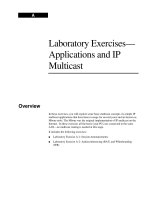
IP Fragmentation (1)
• IP re-assembles at destination only
• Uses fields in header
– Data Unit Identifier (ID)
• Identifies end system originated datagram
– Source and destination address
– Protocol layer generating data (e.g. TCP)
– Identification supplied by that layer
– Data length
• Length of user data in octets
Internal Using in ptithcm 5
IP Fragmentation (2)
– Offset
• Position of fragment of user data in original
datagram
• In multiples of 64 bits (8 octets)
–
More
flag
• Indicates that this is not the last fragment
Fragmentation Example
Dealing with Failure
• Re-assembly may fail if some fragments get lost
• Need to detect failure
• Re-assembly time out
– Assigned to first fragment to arrive
– If timeout expires before all fragments arrive, discard
partial data
• Use packet lifetime (time to live in IP)
– If time to live runs out, kill partial data
Error Control
• Not guaranteed delivery
• Router should attempt to inform source if packet discarded
– e.g. for time to live expiring
• Source may modify transmission strategy
• May inform high layer protocol
• Datagram identification needed
• (Look up ICMP)
No Flow Control
• Allows routers and/or stations to limit rate of incoming data
• Limited in connectionless systems
• Send flow control packets
– Requesting reduced flow
• e.g. ICMP
INTERNET ADDESSES
Internal Using in ptithcm 6
IP Addressing - Overview
IP Addressing - Overview
• Not associated with hardware
• 32-bit Unique Host Address with Hierarchical form:
•Or
• Dotted-decimal Notation: nnn.nnn.nnn.nnn (nnn: 0 to 255). Ex: 100.10.1.50
– Represents a combined subnet/ network number and HOST
number
Host-idNetwork-id
Host-idSubnet-idNetwork-id
Reserved IP Addresses
– Here is:
• IP address= 100.10.20.30
– All Host-id bit with 0 refers to the entire subnet/ network=>
subnet/ network-id
• net-id=100.0.0.0 or network address=100.0.0.0
– All net-id bit with 0 refers to host-id
• host-id=0.10.20.30
– All Host-id bit with 1 refers to all host (broadcast) in subnet/
network
• Broadcast address= 100.255.255.255
– Loop back address= 127.0.0.1
IP Address Classes
a
a
b
b
c
c
d
d
Class A
Network ID
Network ID
Network ID
Host ID
Host ID
Class B
Network ID
Network ID
Network ID
Host ID
Host ID
Class C
Network ID
Network ID
Network ID
Host ID
Host ID
Address Classes
(32 Bit Address 2
32
= 4.2 billion possible addresses)
• There are 5 different address classes
– Class A, B, C for unicast addressing
– Class D for multicast addressing
– Class E for experiment
• Determining the class of the address by looking at the first 4 bits of the IP address:
– Class A begin with 0xxx, or 1 to 126 decimal
– Class B begin with 10xx, or 128 to 191 decimal
– Class C begin with 110x, or 192 to 223 decimal
– Class D begin with 1110, or 224 to 239 decimal
– Class E begin with 1111, or 240 to 254 decimal
Public vs. Private IP addresses
• Public IP: an internet routable IP address, assigned by the Internet Numbering
Authority
• Private IP:
– Private IP addresses are a solution to the problem of the exhaustion of
public IP addresses.
– Addresses that is only used on an internal network not routed on the
Internet backbone:
– Their ranges are:
• 10.x.y.z (10.0.0.0 to 10.255.255.255)
• 172.16.x.y (172.16.0.0 to 172.31.255.255 )
• 192.168.x.y (192.168.0.0 to 192.168.255.255 )
Subnetting
• Subnetting is a way of taking an existing class license and breaking it down to create
more Network Addresses.
– This will always reduce the number of host addresses for a given network.
• Purposes for Organization
• Use of different physical media
• Preservation of address space
•Security
• Control network traffic
• Subnet masks are applied to an IP address to identify the Network portion and the
Host portion of the address.
Internal Using in ptithcm 7
Class B IP address: 140.179.220.200
Subnet Mask: 255.255.192.0
In Binary:
10001100.10110011.11110000.11001000
11111111.11111111.11000000.00000000
10001100.10110011.11000000.00000000
The computer has found that Subnet Address is
140.179.192.0
Subnet Masks
•Subnet masksare applied to an IP address to identify the Network portion and the Host
portion of the address.
• Subnet masks have the form like IP address exception of series of bit “1” that delegates
bits of Network-id and subnet-id if having subneted.
• For examples of determining the subnet address to the IP address below:
• Ip address:
AND
Classless and Prefix
• Classless is used when an organization is granted a block of addresses, it can create
subnets with variable subnet mask lengths to meet its needs.
– Variable-Length Subnet Mask –VLSM
• Classless addressing allows to assign as few or as many variable-sized blocks of IP
addresses as requested.
– Prefix – another name for the common part of the address range (netid)
– Prefix length – the length of the prefix
•
•
ex1: 195.10.100.0
ex1: 195.10.100.0
/24
=> block of 2
=> block of 2
8
8
(255)
(255)
ip
ip
host addresses have the same prefix of 195.10.100.0
host addresses have the same prefix of 195.10.100.0
•
•
ex2: 195.10.100.0
ex2: 195.10.100.0
/26
=> block of 2
=> block of 2
6 (
6 (
64)
64)
ip
ip
host addresses have the same prefix of 195.10.100.192
host addresses have the same prefix of 195.10.100.192
Subnet Masks & Prefix
• In classful addressing, the mask for each block is implicit
– 255.0.0.0 /8
– 255.255.0.0 /16
– 255.255.255.0 /24
• In classless addressing, we need the address and the mask to find the block
the address belongs to (prefix)
Internet Control Message Protocol (ICMP)
Transport
Network
IP
TCP UDP
ICMPARP RARP
Destination unreachable
Echo (Ping)
Others
• ICMP is the component of the TCP/IP protocol
stack that addresses this basic limitation of IP.
• An error/information reporting protocol for IP.
IP header format: Protocol
• 8 bits.
• Indicates which upper-layer protocol
receives incoming packets after IP
processing has been completed
• 06 : TCP 01 : ICMP
• 17 : UDP 08 : EGP
• 8 bits.
• Indicates which upper-layer protocol
receives incoming packets after IP
processing has been completed
• 06 : TCP 01 : ICMP
• 17 : UDP 08 : EGP
Encapsulation of an ICMP in an IP packet
Datagram Header ICMP Header ICMP DataFrame Header
…
Option Data
Option Header
Code
8
Checksum
16
Type
310
Internal Using in ptithcm 8
ICMP Types of Control messages
Address Mask Reply
18
Address Mask Request
17
Information Reply
16
Information Request
15
Timestamp reply. 14
Timestamp. 13
Parameter problem. 12
Time exceeded. 11
Router Selection10
Routers advertisment9
Echo Request8
Redirect / Change request5
Source quench. 4
Destination unreachable. 3
Echo reply. 0
Description Type
• Error ICMP sends the
error report to source
host about:
•Error condition
occurred during
datagram transmission
• Control ICMPs, are used to
inform hosts of conditions
such as network congestion
or the existence of a
better gateway to a
remote network.
• Query ICMP are used to
provide information for
network management
Destination unreachable message
Internet Header + First 64 bits of datagram
Code(0-12)
8
Checksum
16
Unused (must be zero)
Type(3)
310
• The value of 3 in the type field indicates it is a
destination unreachable message.
• The code value indicates the reason the packet could not
be delivered.
Code values for destination unreachable message
Host unreachable for type of device12
Network unreachable for type of device11
Communication with destination network administratively prohibited 10
Communication with destination network administratively prohibited 9
Source Host Isolated8
Destination host unknown7
Destination network unknown6
Source route failed. 5
Fragmentation needed and DF set. 4
Port unreachable. 3
Protocol unreachable. 2
Host unreachable. 1
Net unreachable. 0
Description Code
Error reporting but error correction
Workstation 6
CA
Workstation 1
Fa0/0
ICMP
Destination
unreachable
IP
• ICMP reports on the status of the delivered packet only
to the source device.
• It does not propagate information about network changes
to routers.
• Does not correct the encountered network problem
Destination unreachable
CA
To Z
Send Data
To Z
I don not know
How to get to Z!
Send ICMP
Data network
Destination
unreachable
• An ICMP destination unreachable message is send if:
•Host or port unreachable.
•Network unreachable.
Using ping to test destination reachability
A
CA
Is B
reachable
Yes, I am
here.
B
ICMP echo reply
ICMP echo request
Internal Using in ptithcm 9
ICMP echo messages
Sequence numberIdentifier
…
Option Data
Code (0)
8
Checksum
16
Type (3 or 8)
310
• The value of 0 in the type field indicates it is the echo
request.
• The value of 8 in the type field indicates it is the echo
reply.
Miscellaneous error reporting
Unused ( Must be zero)Pointer
…
Internet Header + First 64 bits of datagram
Code (0-2)
8
Checksum
16
Type (12)
310
• Parameter problem.
• When the code value is 0, the pointer field indicates the
octet of the datagram that produced the error.
Detecting excessively long routes
• When the TTL of the datagram value reaches zero, the
packet is discarded.
• ICMP uses a time exceeded message to notify the source
device that the TTL of the datagram has been exceeded
ICMP redirect/change requests
Unused ( Must be zero)Pointer
…
Internet Header + First 64 bits of datagram
Code (0-2)
8
Checksum
16
Type (12)
310
• Parameter problem.
• When the code value is 0, the pointer field indicates the
octet of the datagram that produced the error.
ICMP redirect/change requests
Router A
172.16.1.100 172.16.1.200
E0
E0
172.16.1.1/24
Default GW:
172.16.1.100
10.0.0.1/8
C
B
Router B
• Router A sends an ICMP redirect/change request to Host
B telling it to use Router B as the gateway to forward all
future requests to network 10.0.0.0/8.
Conditions to send ICMP redirect/change
request
• Default gateways only send ICMP redirect/change
request messages if the following conditions are met:
–The interface on which the packet comes into the
router is the same interface on which the packet
gets routed out.
–The subnet/network of the source IP address is the
same subnet/network of the next-hop IP address of
the routed packet.
–The datagram is not source-routed.
–The route for the redirect is not another ICMP
redirect or a default route.
–The router is configured to send redirects. (By
default, Cisco routers send ICMP redirects. The
interface subcommand no ip redirects will disable
ICMP redirects.)
Internal Using in ptithcm 10
The ICMP redirect/change request
message
…
Internet Header + First 64 bits of datagram
Router Internet address
Code (0-3)
8
Checksum
16
Type (5)
310
• The Router Internet Address field in the ICMP
redirect is the IP address that should be used as
the default gateway for a particular network.
Clock synchronization and transit time
estimation
Transit Timestamp
Sequence numberIdentifier
Receive Timestamp
Originate Timestamp
Code (0)
8
Checksum
16
Type (13 or 14)
310
• Allows a host to ask for the current time according to
the remote host.
• More robust protocols such as Network Time Protocol
(NTP) at the upper layers of the TCP/IP protocol
stack perform clock synchronization in a more reliable
manner.
Information requests and reply message
formats
Sequence numberIdentifier
Code (0)
8
Checksum
16
Type (15 or 16)
310
• Originally intended to allow a host to determine
its network number, is considered obsolete.
• Other protocols
such as BOOTP and Dynamic Host
Configuration Protocol (DHCP) are now used to
allow hosts to obtain their network numbers.
Address mask requirements
…
Address Mask
Sequence numberIdentifier
Code (0)
8
Checksum
16
Type (17 or 18)
310
• Subnet mask is crucial in identifying network, subnet, and
host bits in an IP address.
• If a host does not know the subnet mask, it may send an
address mask request to the local router or broadcast.
• When the router receives the request, it will respond with
an address mask reply. This address mask reply will
identify the correct subnet mask.
Router discovery message
Preferences Level 2
Router address 2
Preferences Level 1
Router address 1
LifetimeAddress entry size
Number of
addresses
Code (0)
8
Checksum
16
Type (9)
310
•Hosts use router discovery message to learn of available routers
(gateway).
•Using the multicast address 224.0.0.2 as the destination address.
May also be broadcast.
•If router that does not support the discovery process, the
solicitation will go unanswered.
Router solicitation message
Reversed
Code (0)
8
Checksum
16
Type (10)
310
•A host generates an ICMP router solicitation message in response
to a missing default gateway.
•This message is sent via multicast and it is the first step in the
router discovery process.
•A local router will respond with a router advertisement
identifying the default gateway for the local host.
Internal Using in ptithcm 11
Congestion and flow control messages
High speed
LAN
S
l
o
w
l
i
n
k
Network congestion is
experienced at the WAN link
• ICMP source-quench messages are used to reduce
the amount of data lost.
• The
source-quench message asks senders to reduce
the rate at which they are transmitting packets.
• Most Cisco routers do not send source-quench
messages by default
•TCP
•UDP
Application Multiplexing Illustrated
TCP and UDP port numbers
Both TCP and UDP use port (or socket) numbers to pass information to the upper layers.
R
F
C
R
F
C
-
-
1
7
0
0
1
7
0
0
More…
Multiplexing of sessions by ports
ETHERNET
IP
TCP
STMP
Web
HTTP
80 25
The same of MAC address :IP address
Port number and socket
Port number and socket :
• Port numbers are used to track multiple sessions that
can occur between hosts.
• Socket=Network address +protocol+ port number
•Example: http://192.168.20.245:8080
Range of ports:
• 2 bytes: 0 – 65535.
– Numbers below 255 : for public applications.
–Numbers from 255 - 1023 : assigned to companies
for marketable applications.
–Numbers above 1023 : are unregulated.
• End systems use port numbers to select proper
applications.
Internal Using in ptithcm 12
Examples of Port number
• Originating source port numbers are dynamically
assigned by the source host; usually, it is a number
larger than 1023.
• Web server application is assigned port 80
• Web client application obtains port 32938
• TCP segment sent from client to server has
– source port number 32938
– destination port number 80
• When web server responds, TCP segment has
– source port number 80
– destination port number 32938
TCP Segment Format
UDP Datagram Format
TCP OPERATION
Transport Layer: TCP
• TCP supplies a reliably transportation between end-user
applications by dealing with the quality-of-service issues of
reliability, flow control, and error correction.
• These are its characteristics:
– Connection-oriented: Establishing end-to-end operations
– Segmenting upper-layer application data
– Sending segments from one end device to another end
device
– Flow control provided by sliding windows
– Reliability provided by sequence numbers and
acknowledgments, re-sends anything not received by
acknowledgement.
– Multiplexing by port numbers
TCP Header format
R
F
C
R
F
C
-
-
7
6
1
7
6
1
•For multiplexing sessions to a certain service
•Such as web with port of 80
TCP Header format
R
F
C
R
F
C
-
-
7
6
1
7
6
1
For flow control and retransmission
Internal Using in ptithcm 13
TCP Header format
R
F
C
R
F
C
-
-
7
6
1
7
6
1
•Error detection
TCP Header format
R
F
C
R
F
C
-
-
7
6
1
7
6
1
URG ACK PSH RST SYN FIN
TCP
• TCP on one computer uses IP to communicate with TCP on
another computer
Reliable Data Transmission
• Positive Acknowledgement
– Receiver returns short message when data arrives
– Call an
acknowledgement
• Retransmission
– Sender starts timer whenever message is
transmitted
– If timer expires before acknowledgement arrives,
sender retransmits message
How Long Should TCP Wait Before
Retransmitting?
• Time for acknowledgement to arrive depends on
– Distance to destination
– Current traffic conditions
• Multiple connections can be open simultaneously
• Traffic conditions change rapidly
Purpose of the transport layer
• IP addresses allow for the routing of packets
between networks. But they made no
provision for
assuring our data reliably
travels end-to-end across
the often vast network path.
• The transport layer is responsible for the
reliable
transport
of and regulation of data flow from source
to destination.
– Sliding windows.
– Sequencing numbers.
– Acknowledgments
Internal Using in ptithcm 14
Synchronization or 3-way handshake
A B
Denial of service attacks
• Denial of service (DoS) attacks are designed to
deny
services to legitimate hosts attempting to establish
connections
.
• DoS attacks are a common method that hackers utilize to
halt system response. One type of DoS is known as SYN
flooding.
• SYN flooding exploits the normal three-way handshake
and causes targeted devices to ACK to source addresses
that will not complete the handshake.
Denial of service attacks
To defend against these attacks
•To defend against these attacks, system administrators
may:
− Decrease
the connection timeout period
− Increase
the connection queue size.
− Software also exists that can detect these types
of attacks and initiate defensive measures.
Windowing and window size:
Sliding window
Sequencing numbers
Internal Using in ptithcm 15
Transport Layer: TCP
• TCP supplies a reliably transportation between end-user
applications.
• These are its characteristics:
– Connection-oriented.
– Supplies a virtual circuit between end-user applications
– Breaking outgoing messages into segments and
reassembles messages at the destination.
– Resends anything not received by acknowledgement.
– Flow control: Windowing.
• The protocols that use TCP include: FTP, HTTP SMTP,
Telnet.
TCP Flow Control
• Receiver
– Advertises available buffer space
– Called the
window
•Sender
– Can send up to entire window before ACK
arrives
• Also called a
sliding window
protocol
Window Advertisement
• Each acknowledgement carries new window
information
– Call
window advertisement
– Can be zero (called
closed window
)
• Interpretation: I have received up through
X
and
can take
Y
more octets
Transport Layer: UDP
• UDP transports data unreliably between hosts.
• Characteristics:
– Connectionless:
• Unreliable, no software checking for message
delivery
•Without acknowledgements.
– No flow control (no window)
– No error recovery (no ACKs)
• Provides application multiplexing (port number)
• Error detection optional (checksum field)
• Transmit messages, does not need reassemble incoming
messages.
UDP Header format
• UDP is a simplest datagram protocol that exchanges datagrams,
only functions of multiplexing and error detecting.
• Applications:
– Routing Protocols
–Streaming Audio
–Gaming
– Video Conferencing
R
F
C
R
F
C
-
-
7
6
8
7
6
8
• Multiplexing by ports Error detection