Heat Transfer Handbook part 2 pptx
Bạn đang xem bản rút gọn của tài liệu. Xem và tải ngay bản đầy đủ của tài liệu tại đây (171.07 KB, 10 trang )
15. Porous Media 1131
Adrian Bejan
16. Heat Pipes 1181
Jay M. Ochterbeck
17. Heat Transfer in Manufacturing and Materials Processing 1231
Richard N. Smith, C. Haris Doumanidis, and Ranga Pitchumani
18. Microscale Heat Transfer 1309
Andrew N. Smith and Pamela M. Norris
19. Direct Contact Heat Transfer 1359
Robert F. Boehm
Author Index 1401
Subject Index 1427
BOOKCOMP, Inc. — John Wiley & Sons / Page 1 / 2nd Proofs / Heat Transfer Handbook / Bejan
1
2
3
4
5
6
7
8
9
10
11
12
13
14
15
16
17
18
19
20
21
22
23
24
25
26
27
28
29
30
31
32
33
34
35
36
37
38
39
40
41
42
43
44
45
[First Page]
[1],
(1)
Lines: 0 to 95
———
11.25609pt PgVar
———
Normal Page
* PgEnds: PageBreak
[1],
(1)
CHAPTER 1
Basic Concepts
ALLAN D. KRAUS
University of Akron
Akron, Ohio
1.1 Heat transfer fundamentals
1.1.1 Introduction
1.1.2 Conduction heat transfer
One-dimensional conduction
One-dimensional conduction with internal heat generation
1.1.3 Spreading resistance
1.1.4 Interface–contact resistance
1.1.5 Lumped-capacity heating and cooling
1.1.6 Convective heat transfer
Heat transfer coefficient
Dimensionless parameters
Natural convection
Forced convection
1.1.7 Phase-change heat transfer
1.1.8 Finned surfaces
1.1.9 Flow resistance
1.1.10 Radiative heat transfer
1.2 Coordinate systems
1.2.1 Rectangular (Cartesian) coordinate system
1.2.2 Cylindrical coordinate system
1.2.3 Spherical coordinate system
1.2.4 General curvilinear coordinates
1.3 Continuity equation
1.4 Momentum and the momentum theorem
1.5 Conservation of energy
1.6 Dimensional analysis
1.6.1 Friction loss in pipe flow
1.6.2 Summary of dimensionless groups
1.7 Units
1.7.1 SI system (Syst
`
eme International d’Unit
´
es)
1.7.2 English engineering system (U.S. customary system)
1.7.3 Conversion factors
Nomenclature
References
1
BOOKCOMP, Inc. — John Wiley & Sons / Page 2 / 2nd Proofs / Heat Transfer Handbook / Bejan
2 BASIC CONCEPTS
1
2
3
4
5
6
7
8
9
10
11
12
13
14
15
16
17
18
19
20
21
22
23
24
25
26
27
28
29
30
31
32
33
34
35
36
37
38
39
40
41
42
43
44
45
[2], (2)
Lines: 95 to 139
———
6.28009pt PgVar
———
Normal Page
PgEnds: T
E
X
[2],
(2)
1.1 HEAT TRANSFER FUNDAMENTALS
1.1.1 Introduction
Practitioners of the thermal arts and sciences generally deal with four basic thermal
transport modes: conduction, convection, phase change, and radiation. The process
by which heat diffuses through a solid or a stationary fluid is termed heat conduction.
Situations in which heat transfer from a wetted surface is assisted by the motion of
the fluid give rise to heat convection, and when the fluid undergoes a liquid–solid
or liquid–vapor state transformation at or very near the wetted surface, attention is
focused on this phase-change heat transfer. The exchange of heat between surfaces,
or between a surface and a surrounding fluid, by long-wavelength electromagnetic
radiation is termed thermal heat radiation.
It is our intent in this section to describe briefly these modes of heat transfer, with
emphasis on an important parameter known as the thermal resistance to heat transfer.
Simple examples are given for illustration; detailed descriptions of the same topics
are presented in specialized chapters.
1.1.2 Conduction Heat Transfer
One-Dimensional Conduction Thermal diffusion through solids is governed
by Fourier’s law, which in one-dimensional form is expressible as
q =−kA
dT
dx
(W) (1.1)
where q is the heat current, k the thermal conductivity of the medium, A the cross-
sectional area for heat flow, and dT /dx the temperature gradient, which, because it
is negative, requires insertion of the minus sign in eq. (1.1) to assure a positive heat
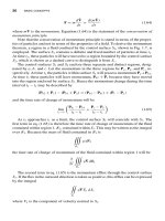
flow q. The temperature difference resulting from the steady-state diffusion of heat
is thus related to the thermal conductivity of the material, the cross-sectional area A,
and the path length L (Fig. 1.1), according to
(T
1
− T
2
)
cd
= q
L
kA
(K) (1.2)
The form of eq. (1.2), where k and A are presumed constant, suggests that in a way
that is analogous to Ohm’s law governing electrical current flow through a resistance,
it is possible to define a conduction thermal resistance as
R
cd
≡
T
1
− T
2
q
=
L
kA
(K/W) (1.3)
One-Dimensional Conduction with Internal Heat Generation Situations
in which a solid experiences internal heat generation, such as that produced by the
flow of an electric current, give rise to more complex governing equations and require
BOOKCOMP, Inc. — John Wiley & Sons / Page 3 / 2nd Proofs / Heat Transfer Handbook / Bejan
HEAT TRANSFER FUNDAMENTALS
3
1
2
3
4
5
6
7
8
9
10
11
12
13
14
15
16
17
18
19
20
21
22
23
24
25
26
27
28
29
30
31
32
33
34
35
36
37
38
39
40
41
42
43
44
45
[3], (3)
Lines: 139 to 173
———
-2.4009pt PgVar
———
Normal Page
PgEnds: T
E
X
[3],
(3)
T
x
Figure 1.1 Heat transfer by conduction through a slab.
greater care in obtaining the appropriate temperature differences. The axial temper-
ature variation in the slim, internally heated conductor shown in Fig. 1.2 is found to
equal
T = T
o
+ q
g
L
2
2k
x
L
−
x
L
2
where T
o
is the edge temperature. When the two ends are cooled to an identical
temperature, and when the volumetric heat generation rate q
g
(W/m
3
) is uniform
throughout, the peak temperature is developed at the center of the solid and is given
by
T
max
= T
o
+ q
g
L
2
8k
(K) (1.4)
Alternatively, because q
g
is the volumetric heat generation q
g
= q/LW δ, the
center–edge temperature difference can be expressed as
T
max
− T
o
= q
L
2
8kLWδ
= q
L
8kA
(1.5)
where the cross-sectional area A is the product of the width W and the thickness δ.
An examination of eq. (1.5) reveals that the thermal resistance of a conductor with a
distributed heat input is only one-fourth that of a structure in which all of the heat is
generated at the center.
BOOKCOMP, Inc. — John Wiley & Sons / Page 4 / 2nd Proofs / Heat Transfer Handbook / Bejan
4 BASIC CONCEPTS
1
2
3
4
5
6
7
8
9
10
11
12
13
14
15
16
17
18
19
20
21
22
23
24
25
26
27
28
29
30
31
32
33
34
35
36
37
38
39
40
41
42
43
44
45
[4], (4)
Lines: 173 to 196
———
-1.48895pt PgVar
———
Long Page
PgEnds: T
E
X
[4],
(4)
x
1
x
2
T
max
T
o
Peak temperature
Edge temperature
x
L
Figure 1.2 Temperature variation in an internally heated conductor.
1.1.3 Spreading Resistance
In configurations where there is a discrete heat source on the surface of a conducting
medium, provision must be made for the lateral spreading of the heat generated
in successive “layers” in the conducting medium below the source. The additional
resistance associated with this lateral flow of heat is called the spreading resistance.
According to Yovanovich and Antonetti (1988), the spreading resistance for a small
heat source on a thick conductor or heat spreader (required to be three to five times
thicker than the square root of the heat source area) can be expressed as
R
sp
=
1 −1.410 +0.344
3
+ 0.043
5
+ 0.034
7
4ka
(K/W) (1.6)
where is the ratio of the heat source area to the substrate area, k the thermal
conductivity of the conductor, and a the square root of the area of the heat source.
For relatively thin conducting layers on thicker substrates, such as encountered
in the cooling of microcircuits, eq. (1.6) cannot provide an acceptable prediction of
R
sp
. Instead, use can be made of the numerical results plotted in Fig. 1.3 to obtain the
requisite value of the spreading resistance.
1.1.4 Interface–Contact Resistance
Heat transfer across the interface between two solids is generally accompanied by
a measurable temperature difference, which can be ascribed to a contact or inter-
face thermal resistance. For perfectly adhering solids, geometrical differences in the
crystal structure (lattice mismatch) can impede the flow of phonons and electrons
BOOKCOMP, Inc. — John Wiley & Sons / Page 5 / 2nd Proofs / Heat Transfer Handbook / Bejan
HEAT TRANSFER FUNDAMENTALS
5
1
2
3
4
5
6
7
8
9
10
11
12
13
14
15
16
17
18
19
20
21
22
23
24
25
26
27
28
29
30
31
32
33
34
35
36
37
38
39
40
41
42
43
44
45
[5], (5)
Lines: 196 to 214
———
7.93205pt PgVar
———
Long Page
* PgEnds: Eject
[5],
(5)
Figure 1.3 Thermal resistance for a circular discrete heat source on a two-layer conducting
medium. (From Yovanovich and Antonetti, 1988.)
across the interface, but this resistance is generally negligible in engineering design.
However, when dealing with real interfaces, the asperities present on each of the sur-
faces (Fig. 1.4) limit actual contact between the two solids to a very small fraction
of the apparent interface area. The flow of heat across the gap between two solids in
nominal contact is by solid conduction in areas of actual contact and fluid conduction
across the “open” spaces. Radiation across the gap can be important in a vacuum
environment or when surface temperatures are high. The heat transferred across an
interface can be found by adding the effects of solid-to-solid conduction and conduc-
tion through the fluid and recognizing that solid-to-solid conduction in the contact
zones involves heat flowing sequentially through the two solids. With the total con-
tact conductance h
co
, taken as the sum of solid-to-solid conductance h
c
and the gap
conductance h
g
,
h
co
= h
c
+ h
g
(W/m
2
· K) (1.7a)
the contact resistance based on the apparent contact area A
a
may be defined as
R
co
=
1
h
co
A
a
(K/W) (1.7b)
In eq. (1.7a), h
c
is given by (Yovanovich and Antonetti, 1988)
h
c
= 1.25k
s
m
σ
P
H
0.95
(1.8a)
BOOKCOMP, Inc. — John Wiley & Sons / Page 6 / 2nd Proofs / Heat Transfer Handbook / Bejan
6 BASIC CONCEPTS
1
2
3
4
5
6
7
8
9
10
11
12
13
14
15
16
17
18
19
20
21
22
23
24
25
26
27
28
29
30
31
32
33
34
35
36
37
38
39
40
41
42
43
44
45
[6], (6)
Lines: 214 to 261
———
0.00914pt PgVar
———
Normal Page
* PgEnds: Eject
[6],
(6)
Figure 1.4 Physical contact between two nonideal surfaces.
where k
s
is the harmonic mean thermal conductivity for solid 1 and solid 2,
k
s
=
2k
1
k
2
k
1
+ k
2
(W/m · K)
σ is the effective root mean square (rms) surface roughness,
σ =
σ
2
1
+ σ
2
2
1/2
(µm)
m is the effective absolute surface slope,
m = (m
2
1
+ m
2
2
)
1/2
P is the contact pressure, and H is the microhardness of the softer material, both in
N/m
2
. In the absence of detailed information, the σ/m ratio can be taken as 5 to 9 µm
for relatively smooth surfaces.
In eq. (1.7a), h
g
is given by
h
g
=
k
g
Y + M
(1.8b)
where k
g
is the thermal conductivity of the gap fluid, Y is the distance between the
mean planes (Fig. 1.4), given by
Y
σ
= 1.185
−ln
3.132
P
H
0.547
BOOKCOMP, Inc. — John Wiley & Sons / Page 7 / 2nd Proofs / Heat Transfer Handbook / Bejan
HEAT TRANSFER FUNDAMENTALS
7
1
2
3
4
5
6
7
8
9
10
11
12
13
14
15
16
17
18
19
20
21
22
23
24
25
26
27
28
29
30
31
32
33
34
35
36
37
38
39
40
41
42
43
44
45
[7], (7)
Lines: 261 to 319
———
12.20604pt PgVar
———
Normal Page
PgEnds: T
E
X
[7],
(7)
and M is a gas parameter used to account for rarified gas effects,
M = αβΛ
where α is an accommodation parameter (approximately equal to 1.7 for air and clean
metals), Λ is the mean free path of the molecules (equal to approximately 0.06 µm
for air at atmospheric pressure and 15°C), and β is a fluid property parameter (equal
to approximately 1.7 for air and other diatomic gases). Equations (1.8a) and (1.8b)
can be added and, in accordance with eq. (1.7a), the contact resistance becomes
R
co
=
1.25k
s
m
σ
P
H
0.95
+
k
g
Y + M
A
a
−1
(1.9)
1.1.5 Lumped-Capacity Heating and Cooling
An internally heated solid of relatively high thermal conductivity that is experiencing
no external cooling will undergo a constant rise in temperature according to
dT
dt
=
q
mc
(K/s) (1.10)
where q is the rate of internal heat generation, m the mass of the solid, and c the
specific heat of the solid. Equation (1.10) assumes that all the mass can be represented
by a single temperature. This approach is commonly called the lumped-capacity
model for transient heating.
Expanding on the analogy between thermal and electrical resistances suggested
previously, the product of mass and specific heat can be viewed as analogous to
electrical capacitance and thus to constitute the thermal capacitance.
When this same solid is externally cooled, the temperature rises asymptotically
toward the steady-state temperature, which is itself determined by the external resis-
tance to heat flow, R. Consequently, the time variation of the temperature of the solid
is expressible as
T(t)= T(t = 0) + qR ( 1 − e
−t/Rmc
)(K) (1.11)
where the product of the external resistance R and the thermal capacitance mc is seen
to constitute the thermal time constant of the system.
1.1.6 Convective Heat Transfer
Heat Transfer Coefficient Convective thermal transport from a surface to a
fluid in motion can be related to the heat tranfser coefficient h, the surface-to-fluid
temperature difference, and the “wetted” surface area S in the form
q = hS(T
s
− T
f
)(W) (1.12)
BOOKCOMP, Inc. — John Wiley & Sons / Page 8 / 2nd Proofs / Heat Transfer Handbook / Bejan
8 BASIC CONCEPTS
1
2
3
4
5
6
7
8
9
10
11
12
13
14
15
16
17
18
19
20
21
22
23
24
25
26
27
28
29
30
31
32
33
34
35
36
37
38
39
40
41
42
43
44
45
[8], (8)
Lines: 319 to 371
———
-3.84573pt PgVar
———
Long Page
* PgEnds: Eject
[8],
(8)
The differences between convection to a rapidly moving fluid, a slowly flowing
fluid, or a stagnant fluid, as well as variations in the convective heat transfer rate
among various fluids, are reflected in the values of h. For a particular geometry and
flow regime, h may be found from available empirical correlations and/or theoret-
ical relations. Use of eq. (1.12) makes it possible to define the convective thermal
resistance as
R
cv
≡
1
hS
(K/W) (1.13)
Dimensionless Parameters Common dimensionless quantities that are used in
the correlation of heat transfer data are the Nusselt number Nu, which relates the
convective heat transfer coefficient to the conduction in the fluid:
Nu ≡
h
k/L
=
hL
k
The Prandtl number Pr, which is a fluid property parameter:
Pr ≡
c
p
µ
k
=
ν
α
the Grashof number Gr, which accounts for the bouyancy effect:
Gr ≡
ρ
2
βgL
3
∆T
µ
2
and the Reynolds number Re, which relates the momentum in the flow to the viscious
dissipation:
Re ≡
ρ
ˆ
VL
µ
All thermal properties in the foregoing dimensionless groups apply to the fluid at its
bulk temperature.
Natural Convection In natural convection, fluid motion is induced by density
differences resulting from temperature gradients in the fluid. The heat transfer coef-
ficient for this regime can be related to the buoyancy and the thermal properties of
the fluid through the Rayleigh number Ra, which is the product of the Grashof and
Prandtl numbers:
Ra ≡
ρ
2
βgc
p
µk
L
3
∆T =
gβ
αν
L
3
∆T
where the fluid properties ρ, β,c
p
, µ, and k are evaluated at the fluid bulk temperature.
Empirical correlations for the heat transfer coefficient in natural convection boundary
layer flow have taken the form
BOOKCOMP, Inc. — John Wiley & Sons / Page 9 / 2nd Proofs / Heat Transfer Handbook / Bejan
HEAT TRANSFER FUNDAMENTALS
9
1
2
3
4
5
6
7
8
9
10
11
12
13
14
15
16
17
18
19
20
21
22
23
24
25
26
27
28
29
30
31
32
33
34
35
36
37
38
39
40
41
42
43
44
45
[9], (9)
Lines: 371 to 411
———
-1.95479pt PgVar
———
Long Page
* PgEnds: Eject
[9],
(9)
h = C
k
L
(Ra)
n
(W/m
2
· K) (1.14)
where n is found to be approximately 0.25 for 10
3
<Ra<10
9
, representing laminar
flow; 0.33 for 10
9
<Ra<10
12
, the region associated with the transition to turbulent
flow; and 0.4 for Ra > 10
12
, when strong turbulent flow prevails. The precise value
of the correlating coefficient C depends on fluid, the geometry of the surface, and
the Rayleigh number range. Nevertheless, for common plate, cylinder, and sphere
configurations, it is found to vary in the relatively narrow range of 0.45 to 0.65 for
laminar flow and 0.11 to 0.15 for turbulent flow past the heated surface.
Natural convection in vertical channels such as those formed by arrays of lon-
gitudinal fins is of major significance. Elenbaas (1942) was the first to document a
detailed study of this configuration, and his experimental results for isothermal plates
were later confirmed numerically by Bodoia and Osterle (1964). A uniform picture
of the thermal transport in such a vertical channel has emerged from these and com-
plementary studies.
It has been shown that the value of the Nusselt number lies between two extremes
that are based on the size of the space between the plates or width of channel. For
wide spacing, the plates appear to have little influence on one another, and the Nusselt
number in this case achieves its isolated plate limit. On the other hand, for closely
spaced plates or for relatively long channels, the fluid attains its fully developed value
and the Nusselt number reaches its fully developed limit. Intermediate values of the
Nusselt number can be obtained from a correlating method suggested by Churchill
and Usagi (1972) for smoothly varying processes, and these values have been verified
by a plethora of detailed experimental and numerical studies.
Thus, the correlation for the average value of h along isothermal vertical channels
spaced z units apart is
h =
k
z
576
El
+
2.873
El
1/2
1/2
(1.15)
where El is the channel Elenbaas number:
El ≡
ρ
2
βgc
p
z
4
∆T
µkL
and ∆T is the surface temperature minus the bulk fluid temperature, ∆T = T
s
−T
f
.
Natural convection fundamentals and results are covered in more detail in Chapter 7.
Forced Convection For forced flow in long or very narrow parallel-plate chan-
nels, the heat transfer coefficient attains an asymptotic value (the fully developed
limit), which for symmetrically heated channel surfaces is equal approximately to
h =
4k
d
e
(W/m
2
· K) (1.16)
where d
e
is the hydraulic diameter defined in terms of the flow area A and the wetted
perimeter of the surfaces p: