Heat Transfer Handbook part 4 ppt
Bạn đang xem bản rút gọn của tài liệu. Xem và tải ngay bản đầy đủ của tài liệu tại đây (166.54 KB, 10 trang )
BOOKCOMP, Inc. — John Wiley & Sons / Page 20 / 2nd Proofs / Heat Transfer Handbook / Bejan
20 BASIC CONCEPTS
1
2
3
4
5
6
7
8
9
10
11
12
13
14
15
16
17
18
19
20
21
22
23
24
25
26
27
28
29
30
31
32
33
34
35
36
37
38
39
40
41
42
43
44
45
[20], (20)
Lines: 940 to 1001
———
0.99356pt PgVar
———
Normal Page
PgEnds: T
E
X
[20],
(20)
F = m
d
ˆ
V
dt
=
d(m
ˆ
V)
dt
(1.64)
where mV is the momentum. Equation (1.64) is the statement of the conservation of
momentum principle.
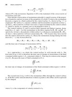
Note that the conservation of momentum principle is stated in terms of the proper-
ties of particles and not in terms of the properties of a field. To derive the momentum
theorem, a region in a fluid confined by the control surface S
1
, shown in Fig. 1.7, is
employed. The surface S
1
contains a definite and fixed number of particles at time t
1
.
At time t
2
, these particles will have moved to a region bounded by the control surface
S
2
, which is shown as a dashed curve to distinguish it from S
1
.
The control surfaces S
1
and S
2
enclose three separate and distinct regions, desig-
nated by a,b, and c. Let the momentum in the three regions be P
a
, P
b
, and P
c
, re-
spectively. At time t
1
the particles within surface S
1
will possess momentum P
a
+P
b1
.
At time t
2
these particles will have momentum, P
b2
+ P
c
because they have moved
into the region enclosed by surface S
2
. Hence the momentum change during the time
interval t
2
− t
1
may be described by
(P
b2
+ P
c
) − (P
b1
+ P
a
) = (P
b2
− P
b1
) + (P
c
− P
a
)
and the time rate of change of momentum will be
lim
t
2
→t
1
P
b
2
− P
b1
t
2
− t
1
+
P
c
− P
a
t
2
− t
1
(1.65)
As t
2
approaches t
1
as a limit, the control surface S
2
will coincide with S
1
. The
first term in eq. (1.65) is therefore the time rate of change of momentum of the fluid
contained within region 1,R
1
, contained within S
1
. This may be written as the integral
over R
1
. Because the mass of fluid contained in R
1
is
R
1
ρ dR
1
the time rate of change of momentum of the fluid contained within region 1 will be
∂
∂t
R
1
ρ
ˆ
V dR
1
The second term in eq. (1.65) is the momentum efflux through the control surface
S
1
. If the flux in the outward direction is taken as positive, this efflux can be expressed
by the integral
S
1
ρ
ˆ
V
ˆ
V
n
dS
1
where V
n
is the component of velocity normal to S
1
.
BOOKCOMP, Inc. — John Wiley & Sons / Page 21 / 2nd Proofs / Heat Transfer Handbook / Bejan
MOMENTUM AND THE MOMENTUM THEOREM
21
1
2
3
4
5
6
7
8
9
10
11
12
13
14
15
16
17
18
19
20
21
22
23
24
25
26
27
28
29
30
31
32
33
34
35
36
37
38
39
40
41
42
43
44
45
[21], (21)
Lines: 1001 to 1042
———
0.42567pt PgVar
———
Normal Page
PgEnds: T
E
X
[21],
(21)
S
1
S
2
c
b
a
Figure 1.7 Regions bounded by control surfaces used for the development of the momentum
theorem.
The conservation of momentum principle then becomes
F = m
d
ˆ
V
dt
=
∂
∂t
R
1
ρ
ˆ
V dR
1
+
S
1
ρ
ˆ
V
ˆ
V
n
dS
1
(1.66)
or, by rearrangement of terms,
∂
∂t
R
1
ρ
ˆ
V
x
dR
1
= F
x
−
S
1
ρ
ˆ
V
x
ˆ
V
n
dS
1
(1.67a)
∂
∂t
R
1
ρ
ˆ
V
y
dR
1
= F
y
−
S
1
ρ
ˆ
V
y
ˆ
V
n
dS
1
(1.67b)
∂
∂t
R
1
ρ
ˆ
V
z
dR
1
= F
z
−
S
1
ρ
ˆ
V
x
ˆ
V
n
dS
1
(1.67c)
in the three rectangular coordinate directions.
The foregoing development leads to the statement of the momentum theorem: The
time rate of increase of momentum of a fluid within a fixed control volume R will
be equal to the rate at which momentum flows into R through its confining surface
S, plus the net force acting on the fluid within R. When the flow is incompressible,
the viscosity is constant, and the flow is laminar, the Navier–Stokes equations result.
In Cartesian coordinates, with F
x
, F
y
, and F
z
taken as the components of the body
force per unit volume, the Navier–Stokes equations are
ρ
∂
ˆ
V
x
∂t
+
ˆ
V
x
∂
ˆ
V
x
∂x
+
ˆ
V
y
∂
ˆ
V
x
∂y
+
ˆ
V
z
∂
ˆ
V
z
∂z
BOOKCOMP, Inc. — John Wiley & Sons / Page 22 / 2nd Proofs / Heat Transfer Handbook / Bejan
22 BASIC CONCEPTS
1
2
3
4
5
6
7
8
9
10
11
12
13
14
15
16
17
18
19
20
21
22
23
24
25
26
27
28
29
30
31
32
33
34
35
36
37
38
39
40
41
42
43
44
45
[22], (22)
Lines: 1042 to 1077
———
1.68011pt PgVar
———
Long Page
* PgEnds: Eject
[22],
(22)
=−
∂P
∂x
+ µ
∂
2
ˆ
V
x
∂x
2
+
∂
2
ˆ
V
x
∂y
2
+
∂
2
ˆ
V
x
∂z
2
+ F
x
(1.68a)
ρ
∂
ˆ
V
y
∂t
+
ˆ
V
x
∂
ˆ
V
y
∂x
+
ˆ
V
y
∂
ˆ
V
y
∂y
+
ˆ
V
z
∂
ˆ
V
y
∂z
=−
∂P
∂y
+ µ
∂
2
ˆ
V
y
∂x
2
+
∂
2
ˆ
V
y
∂y
2
+
∂
2
ˆ
V
y
∂z
2
+ F
y
(1.68b)
ρ
∂
ˆ
V
z
∂t
+
ˆ
V
z
∂
ˆ
V
x
∂x
+
ˆ
V
y
∂
ˆ
V
z
∂y
+
ˆ
V
z
∂
ˆ
V
z
∂z
=−
∂P
∂z
+ µ
∂
2
ˆ
V
z
∂x
2
+
∂
2
ˆ
V
z
∂y
2
+
∂
2
ˆ
V
z
∂z
2
+ F
z
(1.68c)
In cylindrical coordinates with F
r
, F
θ
, and F
z
taken as the components of the body
force per unit volume, the Navier–Stokes equations are
ρ
∂
ˆ
V
r
∂t
+
ˆ
V
r
∂
ˆ
V
r
∂r
+
ˆ
V
θ
r
∂
ˆ
V
r
∂θ
−
ˆ
V
2
θ
r
+
ˆ
V
z
∂
ˆ
V
r
∂z
=−
∂P
∂r
+ µ
∂
2
ˆ
V
r
∂r
2
+
1
r
∂
ˆ
V
r
∂r
−
ˆ
V
r
r
2
+
1
r
2
∂
2
ˆ
V
r
∂θ
2
−
2
r
2
ˆ
V
θ
∂θ
+
∂
2
ˆ
V
r
∂z
2
+ F
r
(1.69a)
ρ
∂
ˆ
V
θ
∂t
+
ˆ
V
r
∂
ˆ
V
θ
∂r
+
ˆ
V
θ
r
∂
ˆ
V
θ
∂θ
−
ˆ
V
r
ˆ
V
θ
r
+
ˆ
V
z
∂
ˆ
V
θ
∂z
=−
1
r
∂P
∂θ
+ µ
∂
2
ˆ
V
θ
∂r
2
+
1
r
∂
ˆ
V
θ
∂r
−
ˆ
V
θ
r
2
+
1
r
2
∂
2
ˆ
V
θ
∂θ
2
+
2
r
2
∂
ˆ
V
r
∂θ
+
∂
2
ˆ
V
θ
∂z
2
+ F
θ
(1.69b)
ρ
∂
ˆ
V
z
∂t
+
ˆ
V
r
∂
ˆ
V
z
∂r
+
ˆ
V
θ
r
∂
ˆ
V
z
∂θ
+
ˆ
V
z
∂
ˆ
V
z
∂z
=−
∂P
dz
+ µ
∂
2
ˆ
V
z
∂r
2
+
1
r
∂
ˆ
V
z
∂r
+
1
r
2
∂
2
ˆ
V
z
∂θ
2
+
∂
2
ˆ
V
z
∂z
2
+ F
z
(1.69c)
Finally, in spherical coordinates with F
r
, F
θ
, and F
φ
taken as the components of
the body force per unit volume and with
D
DT
=
∂
dt
+
ˆ
V
r
∂
∂r
+
ˆ
V
φ
r
∂
∂φ
+
ˆ
V
θ
r sin φ
∂
∂θ
∇
2
=
1
r
2
∂
∂r
r
2
∂
∂r
+
1
r
2
sin φ
∂
∂φ
sin φ
∂
∂φ
+
1
r
2
sin
2
φ
∂
2
∂θ
2
BOOKCOMP, Inc. — John Wiley & Sons / Page 23 / 2nd Proofs / Heat Transfer Handbook / Bejan
CONSERVATION OF ENERGY
23
1
2
3
4
5
6
7
8
9
10
11
12
13
14
15
16
17
18
19
20
21
22
23
24
25
26
27
28
29
30
31
32
33
34
35
36
37
38
39
40
41
42
43
44
45
[23], (23)
Lines: 1077 to 1154
———
2.01216pt PgVar
———
Long Page
* PgEnds: Eject
[23],
(23)
the Navier–Stokes equations are
ρ
D
ˆ
V
r
Dt
−
ˆ
V
2
φ
+
ˆ
V
2
θ
r
=−
∂P
∂r
+ µ
∇
2
ˆ
V
r
−
2
ˆ
V
r
r
2
−
2
r
2
∂
ˆ
V
φ
∂φ
−
2
ˆ
V
θ
cot φ
r
2
−
2
r
2
sin φ
∂
ˆ
V
θ
∂θ
+ F
r
(1.70a)
ρ
D
ˆ
V
φ
Dt
−
ˆ
V
r
ˆ
V
φ
r
−
ˆ
V
2
θ
cot φ
r
=−
1
r
∂P
∂φ
+ µ
∇
2
ˆ
V
φ
+
2
r
2
∂
ˆ
V
r
∂φ
−
ˆ
V
φ
r
2
sin φ
−
2 cos φ
r
2
sin
2
φ
∂
ˆ
V
θ
∂θ
+ F
φ
(1.70b)
ρ
D
ˆ
V
θ
Dt
+
ˆ
V
θ
ˆ
V
r
r
+
ˆ
V
φ
ˆ
V
θ
cot φ
r
=−
ˆ
V
θ
r sin φ
∂P
∂θ
+ µ
∇
2
ˆ
V
θ
−
ˆ
V
θ
r
2
sin
2
φ
+
2
r
2
sin φ
∂
ˆ
V
r
∂θ
+
2 cos φ
r
2
sin
2
φ
∂
ˆ
V
θ
∂θ
+ F
θ
(1.70c)
1.5 CONSERVATION OF ENERGY
In Fig. 1.8, an imaginary two-dimensional control volume of finite size ∆x ∆y with
flow velocity
ˆ
V = e
x
ˆ
V
x
+e
y
ˆ
V
y
, heat flux q
= e
x
q
x
+e
y
q
y
, specific internal energy
u, and rate of internal heat generation q
, the first law of thermodynamics requires
that
rate of energy
accumulation within
the control volume
=
net transfer
of energy by
fluid flow
+
net heat
transfer by
conduction
×
rate of
internal heat
generation
−
net work
transfer from the
control volume to
the environment
(1.71)
Four of the five terms indicated do not involve work transfer from the control volume
to the environment.
• The rate of energy accumulated in the control volume is
∆x ∆y
∂
∂t
(ρu) (1.72a)
BOOKCOMP, Inc. — John Wiley & Sons / Page 24 / 2nd Proofs / Heat Transfer Handbook / Bejan
24 BASIC CONCEPTS
1
2
3
4
5
6
7
8
9
10
11
12
13
14
15
16
17
18
19
20
21
22
23
24
25
26
27
28
29
30
31
32
33
34
35
36
37
38
39
40
41
42
43
44
45
[24], (24)
Lines: 1154 to 1178
———
2.91211pt PgVar
———
Long Page
* PgEnds: Eject
[24],
(24)
∂
∂
()ρe
t
xy⌬⌬
y
x
q
∂q
∂y
yxЉϩ
Љ
⌬⌬
y
y
qyЉ
x
⌬
qx yٞ⌬⌬
qxЉ
y
⌬
q
∂q
∂x
xyЉϩ
Љ
⌬
x
x
⌬
(
(
)
)
ρ
ρ
ˆˆ
Vu
∂
∂y
Vu y x
y
y
ϩ⌬⌬()
ρ
ρ
ˆˆ
Vu
∂
∂y
Vu x y
x
x
ϩ⌬⌬()
ρ
ˆ
V
uy
x
ρ
ˆ
V
ux
y
Figure 1.8 First law of thermodynamics applied to an imaginary control volume in two-
dimensional flow.
• The net transfer of energy by fluid flow is
− (∆x ∆y)
∂
∂x
ρ
ˆ
V
x
u
+
∂
∂y
ρ
ˆ
V
y
u
(1.72b)
• The net heat transfer by conduction is
− (∆x ∆y)
∂q
x
∂x
+
∂q
y
∂y
(1.72c)
BOOKCOMP, Inc. — John Wiley & Sons / Page 25 / 2nd Proofs / Heat Transfer Handbook / Bejan
CONSERVATION OF ENERGY
25
1
2
3
4
5
6
7
8
9
10
11
12
13
14
15
16
17
18
19
20
21
22
23
24
25
26
27
28
29
30
31
32
33
34
35
36
37
38
39
40
41
42
43
44
45
[25], (25)
Lines: 1178 to 1196
———
3.754pt PgVar
———
Long Page
PgEnds: T
E
X
[25],
(25)
• The rate of internal heat generation is
(∆x ∆y)q
(1.72d)
The origin of the term involving the net work transferred from the control volume
to the environment is shown in Fig. 1.9, where the normal and tangential stresses are
sketched. For example, the work done per unit time by the normal stress σ
x
on the left
ρρ
ˆˆ ˆˆ
VV
∂
∂y
VV y x
xy xy
ϩ ()⌬⌬
∂
∂t
()ρ ⌬⌬yx
ˆ
V
x
ρ
ρ
2
2
∂
∂x
xϩ
()
⌬⌬y
ˆ
ˆ
V
V
x
x
ϩ
xy
xy
∂
∂y
yx
⌬
⌬
xy
⌬x
x
y
⌬
ρ
2
y⌬
ˆ
V
x
ˆˆ
VV
xy
x⌬
ϩ
x
x
∂
∂x
xy⌬⌬
Xx y⌬⌬
(
(
)
)
y
x
Figure 1.9 Force balance in the x direction of an imaginary control volume in two-dimensional
flow.
BOOKCOMP, Inc. — John Wiley & Sons / Page 26 / 2nd Proofs / Heat Transfer Handbook / Bejan
26 BASIC CONCEPTS
1
2
3
4
5
6
7
8
9
10
11
12
13
14
15
16
17
18
19
20
21
22
23
24
25
26
27
28
29
30
31
32
33
34
35
36
37
38
39
40
41
42
43
44
45
[26], (26)
Lines: 1196 to 1263
———
3.16624pt PgVar
———
Long Page
* PgEnds: Eject
[26],
(26)
side of the ∆x ∆y element is negative and equal to the force acting on the boundary
σ
y
, multiplied by the boundary displacement per unit time
ˆ
V
x
. This yields −
ˆ
V
x
σ
x
∆
y
.
Similarly, the work transfer associated with normal stresses acting on the right side
of the element is positive and equal to
σ
x
+
∂σ
x
∂x
∆x
ˆ
V
x
+
∂
ˆ
V
x
∂x
∆x
∆y
The net work transfer rate due to these two contributions is
σ
x
∂
ˆ
V
x
∂x
+
ˆ
V
x
∂σ
x
∂x
(∆x ∆y)
Three more work transfer rates can be calculated in the same way by examining
the effect of the remaining three stresses, τ
xy
in the x direction and σ
y
and τ
yx
in the
y direction. This gives
(∆x ∆y)
σ
x
∂
ˆ
V
x
∂x
− τ
xy
∂
ˆ
V
x
∂y
+ σ
y
∂
ˆ
V
y
∂y
− τ
yx
∂
ˆ
V
y
∂x
+ (∆x ∆y)
ˆ
V
x
∂σ
x
∂x
−
ˆ
V
x
∂τ
xy
∂y
+
ˆ
V
y
∂σ
y
∂y
−
ˆ
V
x
∂τ
yx
∂x
where the eight terms have been separated into two groups. It can be shown that the
second group reduces to
− ρ
D
Dt
ˆ
V
2
x
+
ˆ
V
2
y
2
which represents the change of kinetic energy of the fluid in the control volume. This
change may be considered negligible relative to the internal energy change, ∂(ρu)/∂t,
so that the work transfer becomes
(∆x ∆y)
σ
x
∂
ˆ
V
x
∂x
− τ
xy
∂
ˆ
V
x
∂y
+ σ
y
∂
ˆ
V
y
∂y
− τ
yx
∂
ˆ
V
y
∂x
(1.72e)
The stresses σ
x
and τ
xy
can be related to the flow field via the constitutive relations
given by Rohsenow and Choi (1961):
σ
x
= P − 2µ
∂
ˆ
V
x
∂x
+
2
3
µ
∂
ˆ
V
x
∂x
+
∂
ˆ
V
y
∂y
(1.73a)
and
τ
xy
= µ
∂
ˆ
V
x
∂y
+
∂
ˆ
V
y
∂x
(1.73b)
BOOKCOMP, Inc. — John Wiley & Sons / Page 27 / 2nd Proofs / Heat Transfer Handbook / Bejan
CONSERVATION OF ENERGY
27
1
2
3
4
5
6
7
8
9
10
11
12
13
14
15
16
17
18
19
20
21
22
23
24
25
26
27
28
29
30
31
32
33
34
35
36
37
38
39
40
41
42
43
44
45
[27], (27)
Lines: 1263 to 1328
———
0.00224pt PgVar
———
Long Page
* PgEnds: Eject
[27],
(27)
The bookkeeping required by eq. (1.71) dictates the assembly of eqs. (1.72), using
eqs. (1.73), into
ρ
Du
Dt
+ u
Dp
Dt
+ ρ∇·
ˆ
V
=−∇·q
+ q
− P∇·
ˆ
V + µΦ (1.74)
where µ is the dynamic viscosity of the fluid and Φ is the viscous dissipation function,
which is detailed subsequently in rectangular, cylindrical, and spherical coordinates.
However, eq. (1.53) shows that the term in parentheses on the left-hand side of eq.
(1.74) is equal to zero, so that eq. (1.74) reduces to
ρ
Du
Dt
=−∇·q
+ q
− P∇·
ˆ
V + µΦ (1.75)
In the special case where the flow can be modeled as incompressible and two-
dimensional, the viscous dissipation function reduces to
Φ = 2
∂
ˆ
V
x
∂x
2
+
∂
ˆ
V
y
∂y
2
+
∂
ˆ
V
x
∂y
+
∂
ˆ
V
y
∂x
2
(1.76)
To express eq. (1.74) in terms of enthalpy, the definition
h = u + Pv = u +
P
ρ
is invoked. Hence,
Dh
Dt
=
Du
Dt
+
1
ρ
DP
Dt
−
P
ρ
2
Dρ
Dt
(1.77)
Moreover, the heat fluxes q
x
and q
y
can be expressed in terms of local temperature
gradients through use of Fourier’s law:
q
=−k ∇T (1.78)
Thus, the combination of eqs. (1.74), (1.77), and (1.78) results in
ρ
Dh
Dt
=∇·(k ∇T)+ q
+
DP
Dt
+ µΦ −
P
ρ
Dρ
Dt
+ ρ ∇·
ˆ
V
(1.79)
Here, too, eq. (1.53) points out that the terms in parentheses in eq. (1.79) are equal to
zero, so that eq. (1.75) reduces to
ρ
Dh
Dt
=∇·(k ∇T)+ q
+
DP
Dt
+ µΦ (1.80)
Bejan (1995) points out that the change in specific enthalpy for a single-phase fluid
is given by
BOOKCOMP, Inc. — John Wiley & Sons / Page 28 / 2nd Proofs / Heat Transfer Handbook / Bejan
28 BASIC CONCEPTS
1
2
3
4
5
6
7
8
9
10
11
12
13
14
15
16
17
18
19
20
21
22
23
24
25
26
27
28
29
30
31
32
33
34
35
36
37
38
39
40
41
42
43
44
45
[28], (28)
Lines: 1328 to 1411
———
7.50035pt PgVar
———
Long Page
PgEnds: T
E
X
[28],
(28)
dh = Tds+ vdP = Tds+
dP
ρ
(1.81)
where T is the absolute temperature and ds is the specific entrophy change:
ds =
ds
dT
P
dT +
ds
dP
T
dP (1.82)
The last of the Maxwell relations given by Bejan (1997)
∂s
∂P
T
=−
∂(1/ρ)
∂T
P
=
1
ρ
2
∂ρ
∂T
P
=−
β
ρ
(1.83)
where β is the volumetric coefficient of thermal expansion,
β =−
1
ρ
∂ρ
∂T
P
(1.84)
With c
p
taken as the specific heat at constant pressures, it can be shown that
ds
dT
P
=
c
p
T
(1.85)
and eqs. (1.81) through (1.85) can be combined,
dh = c
p
dT +
1
ρ
(1 − βT)dP (1.86)
so that the left-hand side of eq. (1.80) can be written as
ρ
Dh
DT
= ρc
p
DT
Dt
+ (1 − βT)
DP
Dt
(1.87)
Thus, the temperature formulation of the first law of thermodynamics is
ρc
p
DT
Dt
=∇·(k ∇T)+ q
+ βT
DT
Dt
+ µΦ (1.88)
with the special forms for the ideal gas where β = 1/T,
ρc
p
DT
Dt
=∇·(k ∇T)+ q
+
DP
Dt
+ µΦ (1.89a)
and for an incompressible fluid where β = 0,
ρc
p
DT
Dt
=∇·(k ∇T)+ q
+ µΦ (1.89b)
Most convection problems concern an even simpler model where the fluid has
constant thermal conductivity k, neglible viscous dissipation Φ, zero internal heat
BOOKCOMP, Inc. — John Wiley & Sons / Page 29 / 2nd Proofs / Heat Transfer Handbook / Bejan
CONSERVATION OF ENERGY
29
1
2
3
4
5
6
7
8
9
10
11
12
13
14
15
16
17
18
19
20
21
22
23
24
25
26
27
28
29
30
31
32
33
34
35
36
37
38
39
40
41
42
43
44
45
[29], (29)
Lines: 1411 to 1462
———
9.43025pt PgVar
———
Long Page
* PgEnds: Eject
[29],
(29)
generation (q
= 0), and a negligible compressibility effect, βT(DP/Dt)≈ 0. The
energy equation for this model is simply
ρc
p
DT
Dt
= k ∇
2
T (1.90)
or, in the rectangular coordinate system,
ρc
p
∂T
∂t
+
ˆ
V
x
∂T
∂x
+
ˆ
V
y
∂T
∂y
+
ˆ
V
z
∂T
∂z
= k
∂
2
T
∂x
2
+
∂
2
T
∂y
2
+
∂
2
T
∂z
2
(1.91)
in the cylindrical coordinate system,
ρc
p
∂T
∂t
+
ˆ
V
r
∂T
∂r
+
ˆ
V
θ
r
∂T
∂θ
+
ˆ
V
z
∂T
∂z
= k
1
r
∂
∂r
r
∂T
∂r
+
1
r
2
∂
2
T
∂θ
2
+
∂
2
T
∂z
2
(1.92)
and in the spherical coordinate system,
ρc
p
∂T
∂t
+
ˆ
V
r
∂T
∂r
+
ˆ
V
φ
r
∂T
∂φ
+
ˆ
V
θ
r sin φ
∂T
∂θ
= k
1
r
2
∂
∂r
r
2
∂T
∂r
+
1
r
2
sin φ
∂
∂φ
sin φ
∂T
∂φ
+
1
sin
2
φ
∂
2
T
∂θ
2
(1.93)
If the fluid can be modeled as incompressible then, as in eq. (1.89b), the specific
heat at constant pressure c
p
is replaced by c. And when dealing with extremely
viscous flows, the model is improved by taking into account the internal heating due
to viscous dissipation,
ρc
p
DT
Dt
= k ∇
2
T + µΦ (1.94)
In the rectangular coordinate system, the viscous dissipation can be expressed as
Φ = 2
∂
ˆ
V
x
∂x
2
+
∂
ˆ
V
y
∂y
2
+
∂
ˆ
V
z
∂z
2
+
∂
ˆ
V
x
∂y
+
∂
ˆ
V
y
∂x
2
+
∂
ˆ
V
y
∂z
+
∂
ˆ
V
z
∂y
2
+
∂
ˆ
V
z
∂x
+
∂
ˆ
V
x
∂z
2
−
2
3
∂
ˆ
V
x
∂x
+
∂
ˆ
V
y
∂y
+
∂
ˆ
V
z
∂z
2
(1.95)